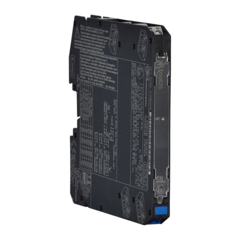
8 D6062 - SIL 2 Vibration Transducer Interface G.M. International ISM0417-0
Start-up
Before powering the unit, check that all wires are properly connected, in particular supply conductors and their polarity and input and output wires.
Check conductors for exposed wires that could touch each other causing dangerous unwanted shorts. When the power supply voltage is turned on, the “power on” green led must be lit.
For 3 wires powered sensors, the sensor negative supply voltage (referred to common terminals “7” / “9”) must be more negative than -17 Vdc (supposing a 15 mA maximum value for
the transducer current consumption).
In addition, for 2 or 3 wires powered sensors, the output signal should be corresponding to the input sensor signal, verifying that the output signal is kept within the 0 to - 20 V range
(supposing a 10 KΩoutput load). Instead, for 2 wires unpowered sensors, the AC output signal should be corresponding to the AC input sensor signal, considering that the output
signal also comprises a -10 Vdc component (absent in the input signal) because of the offset introduced by the DIP switch configuration for 2 wires AC transducers shown in the
“Configuration” section.
Installation
The D6062 series devices are vibration transducer interfaces housed in a plastic enclosure suitable for installation on T35 DIN-Rail according to EN50022, with or without Power Bus,
or on customized Termination Boards.
The D6062 unit can be mounted with any orientation over the entire ambient temperature range.
Electrical connection of conductors up to 2.5 mm² are accommodated by polarized plug-in removable screw terminal blocks which can be plugged inside/outside a powered unit without
suffering or causing any damage.
The wiring cables have to be dimensioned according to their current and length.
In the “Function Diagram” section and on the enclosure side, a block diagram identifies all connections and configurations with 2 or 3 wires sensors.
Identify the function and location of each connection terminal using the wiring diagram in the corresponding section, for example:
Connect a 24 Vdc power supply voltage between terminals “5” (positive pole) and “6” (negative pole).
For 3 wires powered sensors (such as eddy current probes, piezo-ceramic accelerometers and similar sensors), connect the sensor negative supply wire to terminal “10”, the sensor
signal wire to terminal “8” and the sensor common wire (identical for both signal and supply) to terminal “7” or “9”.
For 2 wires powered sensors (such as position, velocity or acceleration sensors, operating in constant current mode), connect the sensor signal wire to terminal “8” and the sensor com-
mon wire to terminal “7” or “9”.
The sensor constant current supply mode is enabled selecting the appropriate DIP switch configurations (see the “Function Diagram” of “Configuration” section).
The sensor supply current is selectable between the three different values of 4 mA, 6 mA and 10 mA. Each supply current value corresponds, as shown in the “Function Diagram” and
“Configuration” sections, to a different DIP switch configuration.
For 2 wires unpowered sensors (such as suspended mass “seismic” accelerometers or other magnetic pick-up sensors), connect the sensor signal wire to terminal “8” and the sensor
common wire to terminal “7” or “9”.
This type of sensor generates AC signals only; therefore, the D6062 input must be biased in order to provide a half scale output value with 0 Vdc input, by selecting the appropriate DIP
switch configuration for 2 wires AC transducers (see the “Function Diagram” of “Configuration” section).
Connect the output signal wire to terminal “1” and the output common wire to terminal “2” (output port for the vibration monitor interface).
Units must be protected against dirt, dust, extreme mechanical (e.g. vibration, impact and shock) and thermal stress, and casual contacts.
If the enclosure needs to be cleaned, use only a cloth lightly moistened by a mixture of detergent in water.
Any penetration of cleaning liquid must be avoided to prevent damage to the unit. Any unauthorized card modification must be avoided.
According to EN61010, the D6062 series must be connected to SELV or SELV-E supplies.
The D6062 series must be installed, operated and maintained only by qualified personnel, in accordance with the relevant national/international installation standards.
Failure to properly installation or use of the equipment may risk to damage the unit or severe personal injury.
The unit cannot be repaired by the end user and must be returned to the manufacturer or his authorized representative. Any unauthorized modification must be avoided
Warning
Operation
The D6062S module provides a fully floating DC supply for energizing vibration transducers, accelerometers or 2-3 wires sensors and repeats the sensor input voltage in a totally isolated
circuit to drive vibration monitors or analyzers for rotating machinery control and supervision purposes.
The module provides 3 port isolation (input / output / supply) and a “POWER ON” green led is lit when the unit is supplied.


