Comeval UNIWAT CV Installation guide

IOM - WAFER SWING CHECK VALVES, UNIWAT® CV
©COMEVAL VALVE SYSTEMS Technical Dept. Ref. IOM - WAFER SWING CHECK VALVES, UNIWAT® CV - Ed.20/06
Comeval Valve Systems reserves the right to alter any technical data contained in this Manual without prior notice. Regularly updated data on www.comeval.es
INSTALLATION, OPERATING
AND MAINTENANCE MANUAL
WAFER SWING CHECK VALVES
1. GENERAL INFORMATION ON THE MANUAL .............2
2. NOTES ON POSSIBLE DANGERS................................2
2.1 Signicance of symbols .............................................2
2.2 Explanatory notes on safety information.....................2
3. PRESERVATION, STORAGE, HANDLING
AND TRANSPORT ............................................................2
4. DESCRIPTION................................................................2
4.1 General Description / Operating principles .................2
4.2 Area of Application......................................................2
4.3 Technical data - remarks ............................................2
4.4 Marking/nameplate .....................................................3
4.5 CE marking. Intended use acc. to PED ......................3
5. INSTALLATION ..............................................................3
5.1 General remarks on installation ..................................3
5.2 Requirements at the place of installation....................4
6. COMMISSIONING & OPERATION.................................4
7. CARE AND MAINTENANCE..........................................5
8. DISMANTLING THE VALVE ..........................................5
9. GOODS RETURN & DISPOSAL ....................................5
10. WARRANTY / GUARANTEE........................................5
11. PARTS LIST..................................................................6
12. ANNEXES.....................................................................6
12.1 Declaration of Conformity .........................................6
12.2 Data Sheet................................................................6
Contents
UNIWAT® CV

IOM - WAFER SWING CHECK VALVES, UNIWAT® CV
©COMEVAL VALVE SYSTEMS Technical Dept. Ref. IOM - WAFER SWING CHECK VALVES, UNIWAT® CV - Ed.20/06
Comeval Valve Systems reserves the right to alter any technical data contained in this Manual without prior notice. Regularly updated data on www.comeval.es
1. GENERAL INFORMATION ON THE MANUAL
- This Manual provides information on safely using the product, being binding for preservation, storage, handling, trans-
port, installation, commissioning, operation, maintenance, repair and disposal, and must be thoroughly observed at any
step.
- Please contact the supplier or the manufacturer in case of issues which cannot be solved by reference to this Manual.
- Any deviation from this Manual and sound engineering practice or modication on the product shall be notied to ma-
nufacturer for advice or approval.
- In addition, regional safety requirements must be always applied and observed at any step.
- All the work related to the product must be carried out, supervised and inspected by specialist personnel. It is the
owner’s responsibility to dene areas of responsibility and competence and to ensure the proper monitoring.
- This Manual is in accordance with Directive 2014/68/EU on Pressure Equipment (PED).
- For ATEX applications, please refer to ATEX Specic instructions.
- The manufacturer reserves the right to make technical modications at any time.
2. NOTES ON POSSIBLE DANGERS
2.1 Signicance of symbols
ATTENTION!
. . . Warning of general danger
2.2 Explanatory notes on safety information
In this Manual dangers, risks and items of safety information are highlighted to attract special attention.
Information marked with the symbol above describes practices, which if fail to comply with, can result in serious injury or
danger of death for users or third parties or in material damage to the system or the environment. It is vital to comply with
these practices and to monitor compliance.
The rest of information not specically emphasized in this Manual, along with Data Sheet and product marking, must also
be observed and complied with for safely using the product.
3. PRESERVATION, STORAGE, HANDLING AND TRANSPORT
- Use proper packing for transportation.
- Keep storage protection before installation.
- In order to prevent damage, corrosion or rust on the surface, avoid extreme temperatures (keep at 5ºC to 50ºC), avoid
high environmental humidity or corrosive environment. Keep the valves away from direct sunlight, dust, ames or rain.
Protect rubbers also against UV light. Do not pile up excessive weight. In case of severe bumping inspect the material for
any damage and replace if necessary.
4. DESCRIPTION
4.1 General Description / Operating principles
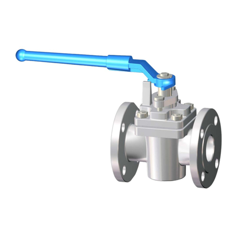
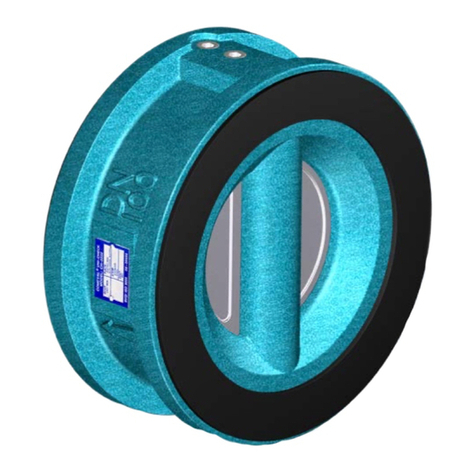
Wafer Swing Check Valves are devices for preventing the reverse of ow in a piping system, by means of its articulated
disc, that opens with positive ow and closes against a pressure reversal. Valve diagram with parts can be seen at the
last page of the Manual.
4.2 Area of Application
They are a light, compact and economic anti-return device option for dierent applications such as heating systems,
water treatment, pumping, etc.
4.3 Technical data - remarks
For data such as main features, duties/limits of use, dimensions, weights, etc. refer also to Data Sheet.
Page 2
ATTENTION!
- Protect against external force (impacts, vibrations, etc.).
- Allow only skilled personnel; suitable handling and lifting equipment must be used. See Data Sheet for weights or
consult manufacturer.
- Always use suitable protection equipment, and minimize the use of human body force at any step to avoid injuries.
- There is a risk of body member (hand, nger, arm…) crushed against any other solid element (wall, pipe, oor,
etc.) during handling. Take this into account and handle with care.
- There is a crushing hazard between the disc and the seat. Ensure the disc is in rest position in case a hand is
introduced inside the valve.
IOM - WAFER SWING CHECK VALVES, UNIWAT® CV
©COMEVAL VALVE SYSTEMS Technical Dept. Ref. IOM - WAFER SWING CHECK VALVES, UNIWAT® CV - Ed.20/06
Comeval Valve Systems reserves the right to alter any technical data contained in this Manual without prior notice. Regularly updated data on www.comeval.es
4.4 Marking/nameplate
Nameplate/label description of the valve:
4.5 CE marking. Intended use acc. to PED
* Classication of uids group 2 acc. to Directive 2014/68/EU, Article 13.
Check valve selection, material compatibility, pressure and temperature limits and other essential parameters. Ensure
proper safety devices/measures are implemented to prevent exceeding intended use of the product. Contact the manu-
facturer for advice in case of pressure tests exceeding the intended use. Refer to Data Sheet and consult the manufac-
turer for further information.
5. INSTALLATION
5.1 General remarks on installation
The following points should be taken into account in addition to the general principles governing installation work:
Page 3
ATTENTION!
- Before installation, make sure previous chapters are thoroughly followed.
- Ensure safe access and working conditions for proper performance.
- Observe all applicable safety measures during installation.
- Remove remaining packing/storage protection if present.
- Lay pipelines such that damaging transverse, bending and torsional forces are avoided.
- Protect valves from dirt during construction work. The interior of the valve and the pipeline must be free of fo-
reign particles.
- Protect the valve soft parts from heating caused by welding works at the plant during commissioning.
- Avoid mechanical damage to the disc and O-rings.
- Follow the arrow in the label for normal ow direction for installation. The valve can be installed either in vertical
pipelines with normal ow upwards or in horizontal pipelines. The valve is supplied with an eyebolt to ease its
correct positioning and assembly.
Please consult with our Technical Department in the following cases:
- Working pressures below 0,1 bar / low ow, that can lead to partial opening/instable range.
- Very low back pressure when leakage in the reverse ow direction is not permissible.
- There is a crushing hazard between the disc and the seat. Ensure the disc is in rest position in case a hand is
introduced inside the valve.
- When installing the valve, there is a crushing hazard between valve and pipe system. Mind the hands to avoid it.
- VALVE ASSEMBLY IN THE PIPE SYSTEM: The valve is wafer type for installation between anges. Remove
impurities in the contact faces. The valve is comprehensive of body O-rings, hence do not add additional gaskets
between valve and counteranges. Pipe must be properly aligned and supported. Introduce two consecutive bolts
(at bottom in horizontal pipeline). Then hold the valve by the eyebolt (eyebolt must remain on top in horizontal
pipeline) and introduce it between counteranges by the opposite side down to the bolts. Once the valve centred
between counteranges, set the rest of bolts and tighten with nuts in a crosswise, moderate and uniform manner.
Do not use tightening to correct misalignments or gap between valve and counteranges. This could lead to
tensions and damages.
PS DN
≤300 350-600
10
16
Liquids of group 2*compatible with materials of construction,
acc. to Directive 2014/68/EU Annex II table 9 up to category I
Marcado Descripción
CE-Marking
Manufacturer logo
www.comeval.es Website of manufacturer
UNIWAT® Brand
FIG Valve type (CVCCE, CVIIE…)
SSeat material (EPDM, NBR))
Y.VV Manufacturing year
(Y.16 = 2016)
ZZZZZ-N Batch / Serial no.
TS Max. / min. temperature
B Body material
D Disc material
PED 2014/68/EU Directive 2014/68/UE
SEP Sound Engineering Practice
FCounteranges to be used
(PN10, PN16…)
PN Nominal pressure
(max. pressure in bar)
DN Nominal diameter
Arrow showing normal ow
direction

IOM - WAFER SWING CHECK VALVES, UNIWAT® CV
©COMEVAL VALVE SYSTEMS Technical Dept. Ref. IOM - WAFER SWING CHECK VALVES, UNIWAT® CV - Ed.20/06
Comeval Valve Systems reserves the right to alter any technical data contained in this Manual without prior notice. Regularly updated data on www.comeval.es
5.2 Requirements at the place of installation
- Downstream from a disruptive element (pump, valve, elbow, pipe reduction) leave as much distance as possible; mini-
mum distance recommended: 6 times the valve diameter (6xDN).
- Upstream from a disruptive element leave at least a distance of 2xDN.
- Aggressive environmental conditions may reduce the life span of the product. Consider special construction/protective
measures in such a case.
- Consider the interaction between the system and the equipment. Foresee elements to absorb vibrations, pipe dilata-
tions, guides, anchoring and proper support according to the weight of the components.
- The system and operation protocol should be conceived in such a way to avoid high velocities. Prevent pulsing ow or
water hammers, which are very harmful for valves and the rest of the components.
- Flooding of the product is not recommended.
- Allow enough space for valve installation, operation and maintenance.
- It is recommended to install a proper sized mesh strainer upstream the valve in order to protect seating surfaces from
abrasion or erosion that could lead to seat leakage.
- Planners / construction companies or the owner are responsible for positioning and installing products.
6. COMMISSIONING & OPERATION
- In case of risk of media freezing inside the valve, take due measures to avoid it.
Page 4
ATTENTION!
- Before commissioning the valve, check the material, pressure, temperature, ow direction and other essential
parameters. Always use the product within the scope of intended service and operating duties.
- Before commissioning, make sure previous chapters have been thoroughly followed.
- Regional safety instructions should be adhered to.
- It is essential to ush the pipe system thoroughly to eliminate all the particles and impurities which could remain
in the pipes and particularly welding residue, chips, tool remains, etc. that could damage the equipment during
start-up. Ensure that during cleaning of the pipe system, any chemicals used and temperature are compatible
with the valve construction.
- Temperatures above 50ºC or below 0ºC may cause personnel injuries if valves are touched.
- Leakage of media through valve, between counteranges or at closing may also cause scalding, health harm,
pollution, re or damage to other parts of the installation depending on the media.
Use suitable protection equipment when approaching the valve, ensure that the corresponding warning signs are
displayed on the valve or surrounding area, and/or isolate the equipment in case of danger.
- Before commissioning a new plant or restarting it after repairs or modication, always ensure that:
- All work has been completed correctly.
- The valve is in the correct position for its function.
- Safety devices/ measures have been implemented.
- The lling, warming-up and starting-up of the system shall be gradual so as to avoid any inadmissible stress. Check
for tightness in valve connections, and retighten crosswise and gradually if necessary until leakage elimination.

IOM - WAFER SWING CHECK VALVES, UNIWAT® CV
©COMEVAL VALVE SYSTEMS Technical Dept. Ref. IOM - WAFER SWING CHECK VALVES, UNIWAT® CV - Ed.20/06
Comeval Valve Systems reserves the right to alter any technical data contained in this Manual without prior notice. Regularly updated data on www.comeval.es
7. CARE AND MAINTENANCE
The operator must dene maintenance and maintenance-intervals to meet requirements.
- Check for body, seat and connections tightness.
After any maintenance work please refer to chapters 5 and 6 for installation / commissioning.
Recommended Spare parts:
Use only original spare parts.
It is advisable to have spare O-rings to replace them regularly. Type and number of each spare part to be stored accor-
ding to many factors: service level, valves quantity, etc.
8. DISMANTLING THE VALVE
9. GOODS RETURN & DISPOSAL
- For any returned goods, the issuing company must provide information in written on any hazards and the precaution
in case of potentially polluting or harmful residues, or any mechanical damage that could present a health, safety or
environmental risk, as enforced by EU Health, Safety and Environment Law, including the Safety Data Sheet of the
substances identied as potentially hazardous.
- Valves are recyclable and not expected hazard to the environment, with the exception of soft parts (PTFE and rubber
compounds) that should be disposed separately only by approved procedure, and no incineration is permitted.
10. WARRANTY / GUARANTEE
- The extent and period of warranty cover are specied in the “General Sales Terms” of COMEVAL VALVE SYSTEMS
valid at the time of delivery or, by way of departure, in the contract of sale itself.
- We guarantee freedom of faults in compliance with state-of-the-art technology and the conrmed application.
- No warranty claims are accepted for any damage caused as the result of incorrect handling or disregard of this Manual,
Data Sheet and relevant regulations.
- This warranty also does not cover any damage which occurs during operation under conditions deviating from those
laid down by specications or other agreements.
- Justied complaints will be eliminated by repair carried out by us or by a specialist appointed by us.
- No claims will be accepted beyond the scope of this warranty. The right to replacement delivery is excluded.
- The warranty shall not cover maintenance work.
- Our guarantee coverage does not cover for any commissioning, maintenance or installation of the product or external
parts.
- Our guarantee does not cover products proved to have been tampered with or faulted by material wear and tear.
- The Purchaser is responsible for checking that the incoming product is received in good condition and conforms to the
ordered specications. In case of damage caused during transit it is necessary to immediately complain to the carrier
within 24 hours. After this time carriers could not assume the derived costs. In case of any deviation in relation to order
specications, please contact us.
Page 5
ATTENTION!
- Before disassembling the valve, note chapters 3, 8 & 10.
- There is a crushing hazard between the disc and seat. Ensure the disc is in rest position in case a hand,
etc. is introduced inside the valve.
- Check the valve surface inside and outside. If advanced corrosion or erosion is observed, double check
service and valve features and replace the valve properly.
ATTENTION!
The following points must be observed:
- Pressureless pipe system.
- Medium must be cool.
- Plant must be drained.
- Note chapter 3 for proper handling and lifting.
- Additionally, in case of toxic, corrosive, ammable or caustic media:
- Purge pipe system carefully.
- Use proper protection equipment to avoid health harm.
- Adopt proper actions to avoid pollution of the environment.
COMEVAL VALVE SYSTEMS, S.L. y CIA., Soc. Comanditaria
Les Rotes, 15 46540 El Puig (Valencia) España
Phone +34 961 479 011 ·Fax +34 961 472 799

IOM - WAFER SWING CHECK VALVES, UNIWAT® CV
©COMEVAL VALVE SYSTEMS Technical Dept. Ref. IOM - WAFER SWING CHECK VALVES, UNIWAT® CV - Ed.20/06
Comeval Valve Systems reserves the right to alter any technical data contained in this Manual without prior notice. Regularly updated data on www.comeval.es
11. PARTS LIST
12. ANNEXES
12.1 Declaration of Conformity - DC04EN
12.2 Data Sheet - DS04
Page 6
Nº PART
1Body
2 Disc
3Eye bolt
4Seat O-Ring
5Face O-Ring
6Retainer screw
7 Disc bearing
Updated documents on www.comeval.es
Table of contents
Other Comeval Control Unit manuals

Comeval
Comeval MAXOMATIC Series Installation guide

Comeval
Comeval UNIFLOW BV BT-B9 Installation guide

Comeval
Comeval UNIFLOW 3P Installation guide

Comeval
Comeval UNIWAT CH Series Installation guide

Comeval
Comeval UNIFLOW PP Series Installation guide

Comeval
Comeval Uniwat 3240 Installation guide

Comeval
Comeval UNIWAT VF791 Series Installation guide

Comeval
Comeval UNIFLOW DP Series Installation guide