manuals.online logo
Brands
  1. Home
  2. •
  3. Brands
  4. •
  5. COMEXIO
  6. •
  7. Network Hardware
  8. •
  9. COMEXIO UI-Modul User manual

COMEXIO UI-Modul User manual

Anleitung/Instruction:
UI-Modul
DE
Beachten und befolgen Sie die Instruktionen bzw. technischen Daten aus dem
Handbuch und dem Datenblatt. Diese finden Sie auf der Homepage
comexio.com.
Die Installation darf nur durch eine Elektrofachkraft oder einer elektrotechnisch
unterwiesenen Person erfolgen.
EN
Note and follow the instructions or technical data from the manual and the data
sheet. These can be found on the homepage comexio.com.
Installation may only be performed by a qualified electrician or an electrically
instructed person.
Schnellstart/Quick Start
DE
Installation:
1. Schließen Sie alle benötigten Ein- und Ausgänge
an das UI-Modul an.
2. Verbinden Sie die Erweiterung in Reihe mit
Ihrem IO-Server über ein Extension-Verbinder-
Kabel (ZC008) oder ein geschirmtes Kabel z. B.
Cat5.
3. Schieben Sie beim ersten und letzten Gerät den
Kodierschalter nach links und bei allen anderen
Geräten nach rechts (siehe Bild 2).
4. Setzen Sie die Jumper für die gewünschte
Funktionalität PT1000/DI (siehe Bild 3)
5. Schalten Sie die Spannungsversorgung ein. Die
LED blinkt für ca. 3 Sekunden, anschließend
leuchtet diese, d.h. die Erweiterung ist
betriebsbereit.
Inbetriebnahme:
1. Aktivieren Sie die Erweiterungen im
Webinterface unter dem Menüpunkt „Geräte“
→„Extension hinzufügen“. Klicken Sie auf den
Button „Suche neue lokale Erweiterungen“
und fügen die Erweiterung hinzu.
2. Benennen Sie die Ein- und Ausgänge im
Webinterface unter dem Menüpunkt „Geräte“
und aktivieren bzw. deaktivieren Sie nicht
benötigte Ein- und Ausgänge.
3. Stellen Sie die gewünschte Funktionalität der
Ein- bzw. Ausgänge ebenfalls unter dem
Menüpunkt „Geräte“ korrekt ein.
Ab jetzt stehen Ihnen die Ein- und Ausgänge der
Erweiterung (mit den zugehörigen Bezeichnungen)
für die Programmierung und Visualisierung zur
Verfügung.
EN
Installation:
1. Connect all necessary inputs and outputs to the
UI-Module.
2. Connect the extension in series with your
IO-Server using an extension connector cable
(ZC008) or a shielded cable e.g. Cat5.
3. Slide the coding switch of the first and last unit
to the left and all other devices to the right (see
Figure 2).
4. Set the jumpers for the desired PT1000/DI
functionality (see Figure 3).
5. Turn on the power supply. The LED flashes for
about 3 seconds, then lights up, i.e. the
extension is ready for operation.
Commissioning:
1. Enable extensions in the web interface under
the menu item “Devices”→“Add extension”.
Click on the button “Search for local
extensions”and add the extension.
2. Enter the inputs and outputs in the web
interface under the menu item “Devices”and
activate or deactivate unneeded inputs and
outputs.
3. Set the desired functionality of the inputs or
outputs correctly under the "Devices" menu.
From now on the inputs and outputs of the
extension are available (with the associated
names) for programming and visualization.
Bild 2 | Figure 2
Bild 3 | Figure 3
Übersicht (Bild 1)
1. Anschluss Extension Verbinder
2. Stromversorgung 24V DC
3. Extension Bus (Erweiterungsbus)
4. Digitaleingänge 12V-24V DC oder PT1000
5. Digitaleingänge 12V-24V DC
6. Kodierschalter
7. Jumper Kodierung PT1000 oder
Digitaleingänge 12-24V DC (Bild 3)
8. Digitaleingänge 12V-24V DC oder
Analogeingänge 0-10VDC
9. Analogausgänge 0-10V DC
10. Digitaleingänge 12V-24V DC oder 4-20mA
Messeingänge
Overview (Figure 1)
1. Connection extension connector
2. Power supply 24V DC
3. Extension bus
4. Digital inputs 12V-24V DC or PT1000
5. Digital inputs 12V-24V DC
6. Coding switch
7. Jumper coding PT1000 or digital inputs 12-24V
DC (Figure 3)
8. Digital inputs 12V-24V DC or analog inputs
0-10VDC
9. Analog outputs 0-10V DC
10. Digital inputs 12V-24V DC or 4-20mA
measuring inputs
Bild 1 | Figure 1
Technische Daten/Technical Data
Stromversorgung
24V DC
Power supply
Digitaleingänge
12x 24V DC
Universal Inputs
Analogeingänge
4 x 0V bis/to 10V
analogue Inputs
Analogausgänge
4 x 0V bis/to 10V
analogue Outputs
PT1000 Eingang
1x PT100 –PT1000 (100Ωbis/to 1kΩat 0°C)
PT1000 Input
Leistungsaufnahme
2-3W
Power consumption
Anschluss |
Connection
Funktion 1 |
Function 1
Funktion 2 |
Function 2
Anschluss |
Connection
Funktion 1 |
Function 1
Funktion 2 |
Function 2
U1
Digital Input 1
PT1000 + (Jumper)
U9
Analog Output 1
U2
Digital Input 2
PT1000 –(Jumper)
U10
Analog Output 2
U3
Digital Input 3
U11
Analog Output 3
U4
Digital Input 4
U12
Analog Output 4
U5
Digital Input 5
Analog Input 1
U13
Digital Input 9
4-20mA Input 1
U6
Digital Input 6
Analog Input 2
U14
Digital Input 10
4-20mA Input 2
U7
Digital Input 7
Analog Input 3
U15
Digital Input 11
4-20mA Input 3
U8
Digital Input 8
Analog Input 4
U16
Digital Input 12
4-20mA Input 4
Achtung:
Attention:
Die Funktionen lassen sich nur blockweise umschalten.
The functions can only be switched block by block.
Zubehör/
Accessories
COMEXIO IO-Server
CMS120
Extension-Verbinderkabel/Extension connector
cable
ZC008
Netzteil 24V DC 30W/Power supply unit 24V DC
30W
ZC101
Eisenberger Str. 56a
67304 Kerzenheim
Deutschland
Telefon:
06351 - 47804 0
Fax:
06351 - 47804 99
http://www.comexio.com
info@comexio.com

Other COMEXIO Network Hardware manuals

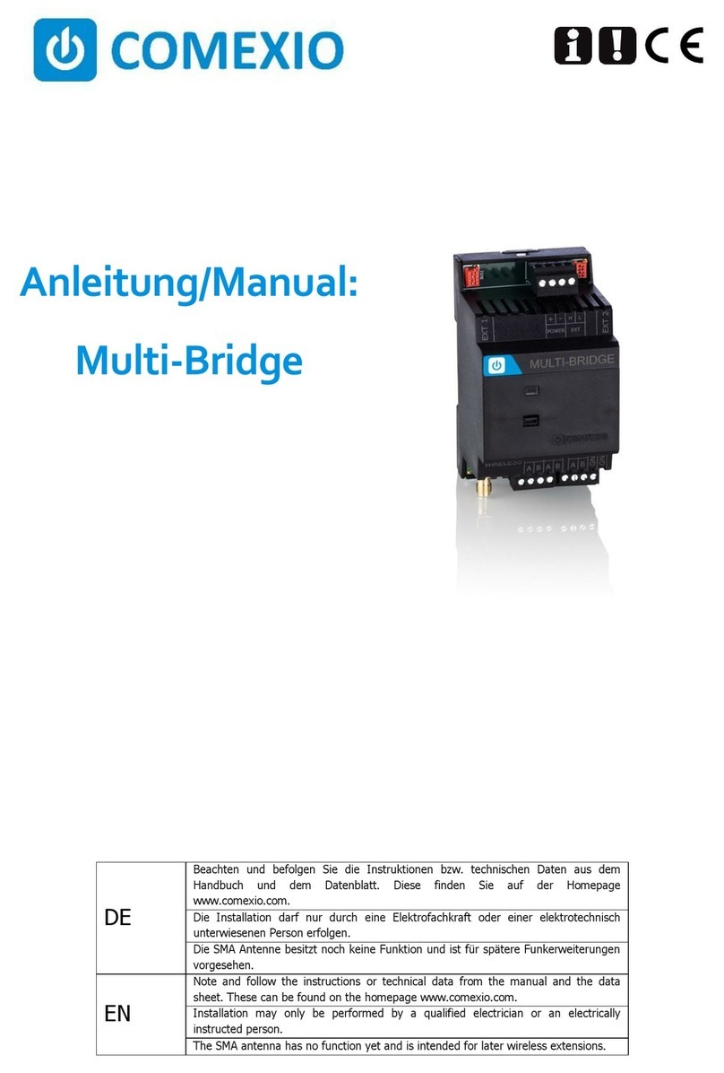
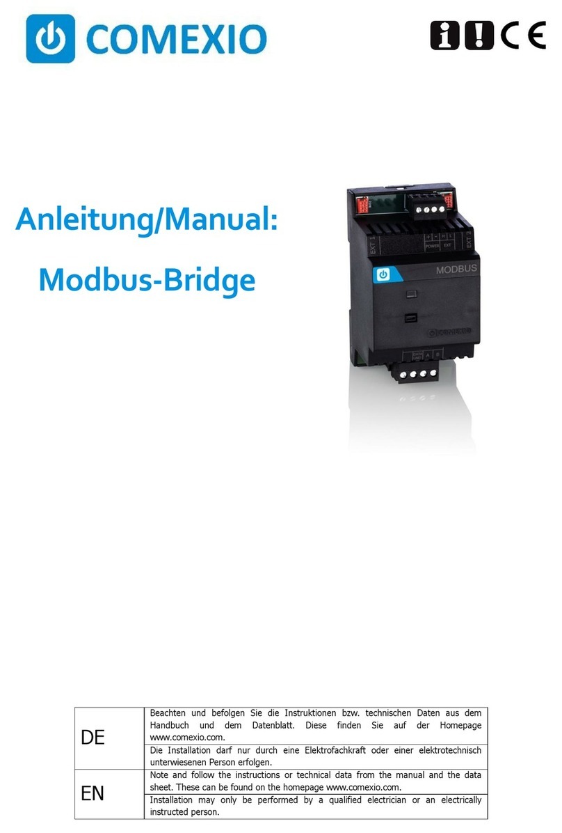
COMEXIO Modbus-Bridge CME910 User manual

COMEXIO

COMEXIO Modbus-Bridge CME910 User manual

COMEXIO CME820 User manual

COMEXIO

COMEXIO CME820 User manual

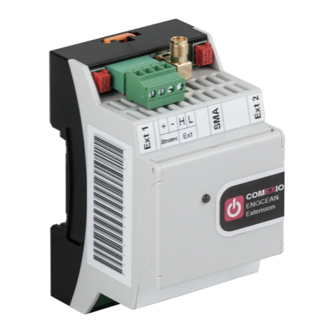
COMEXIO EnOcean Unit User manual

COMEXIO

COMEXIO EnOcean Unit User manual

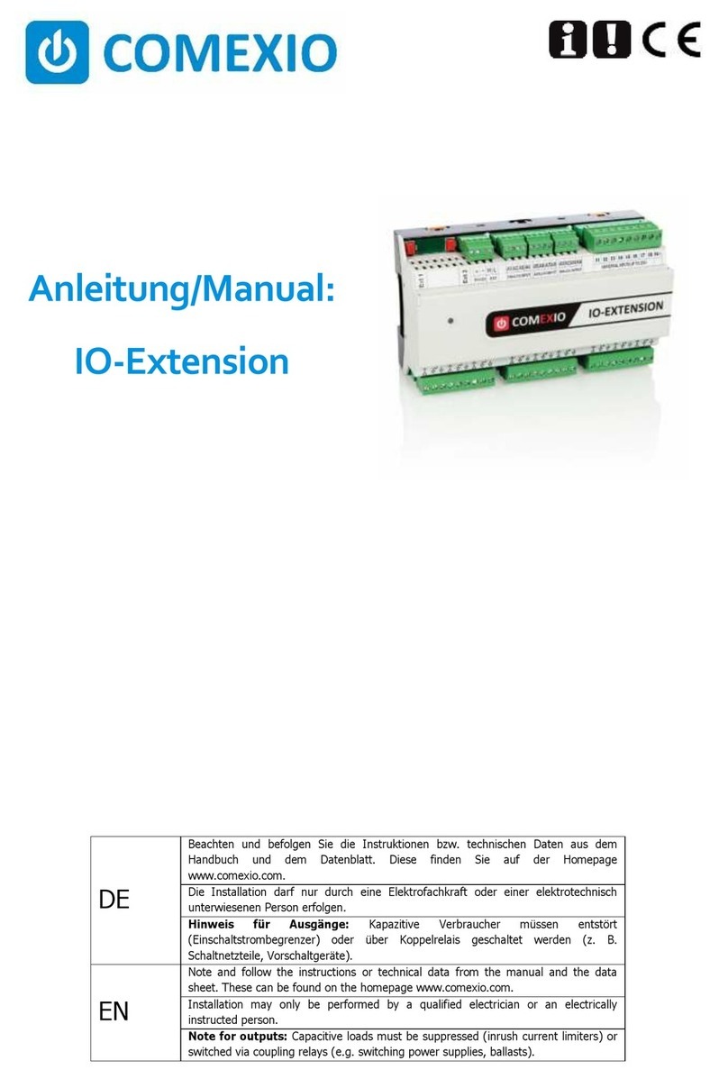
COMEXIO IO-Extension User manual

COMEXIO

COMEXIO IO-Extension User manual

Popular Network Hardware manuals by other brands

Mobatime NTS IT Quick installation guide

Mobatime

Mobatime NTS IT Quick installation guide

NETGEAR ProSecure UTM150 installation guide

NETGEAR

NETGEAR ProSecure UTM150 installation guide

BT I-Plate manual

BT

BT I-Plate manual

Meinberg LANTIME M600 manual

Meinberg

Meinberg LANTIME M600 manual

Teletronics International EZ Bridge 802.11G Product guide

Teletronics International

Teletronics International EZ Bridge 802.11G Product guide

Intuicom RTK Bridge-X installation guide

Intuicom

Intuicom RTK Bridge-X installation guide

Imron Corporation Azure Access BLU-RI2M Hardware manual

Imron Corporation

Imron Corporation Azure Access BLU-RI2M Hardware manual

HP 180 Degree Turn Product review

HP

HP 180 Degree Turn Product review

HP HPE Synergy 12000 Frame Setup and installation guide

HP

HP HPE Synergy 12000 Frame Setup and installation guide

Inaxsys STORM INS88NVR1T user manual

Inaxsys

Inaxsys STORM INS88NVR1T user manual

Cradlepoint AER2200 Series quick start guide

Cradlepoint

Cradlepoint AER2200 Series quick start guide

Telex Communications 2472AA instruction manual

Telex Communications

Telex Communications 2472AA instruction manual

PairGain HLU-431 manual

PairGain

PairGain HLU-431 manual

2N OfficeRoute quick guide

2N

2N OfficeRoute quick guide

NetApp ASA A400 Installation

NetApp

NetApp ASA A400 Installation

Alcatel-Lucent 5620 user guide

Alcatel-Lucent

Alcatel-Lucent 5620 user guide

network MR-TR-C1 Series user manual

network

network MR-TR-C1 Series user manual

Castelle Premier Quick reference guide

Castelle

Castelle Premier Quick reference guide

manuals.online logo
manuals.online logoBrands
  • About & Mission
  • Contact us
  • Privacy Policy
  • Terms and Conditions

Copyright 2025 Manuals.Online. All Rights Reserved.