Comfort Flex CLIV-ACC-036-A3S User manual

Comfort Flex
Rev: February 5th 2016
General Manual and Specifications Document
MINI-CHILLER
This manual
Applies to:
CLIV Series
Thank you for selecting a Comfort Flex unit. Please read
this manual before installation and operation.

Comfort Flex
Rev: February 5th 2016
Installation Manual
CLIV Series

Comfort Flex
Rev: February 5th 2016
GENERAL DESCRIPTION
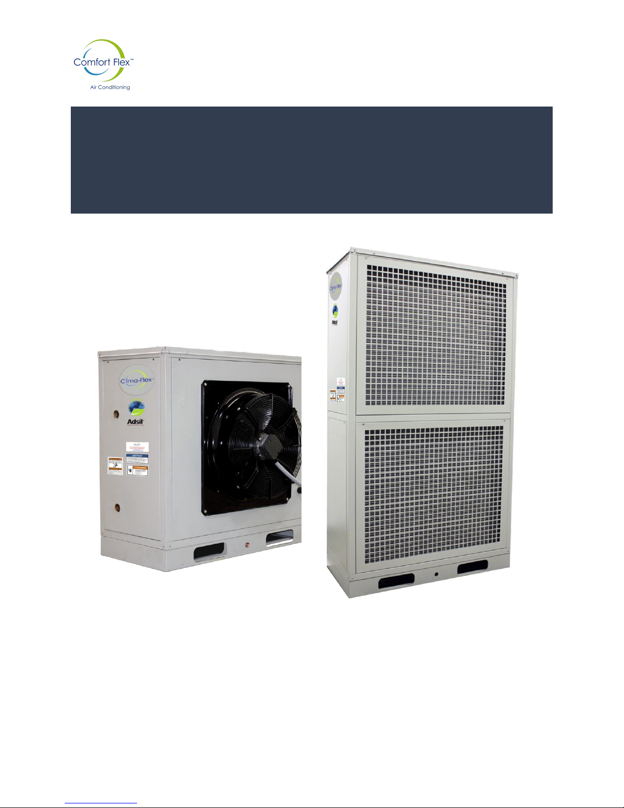
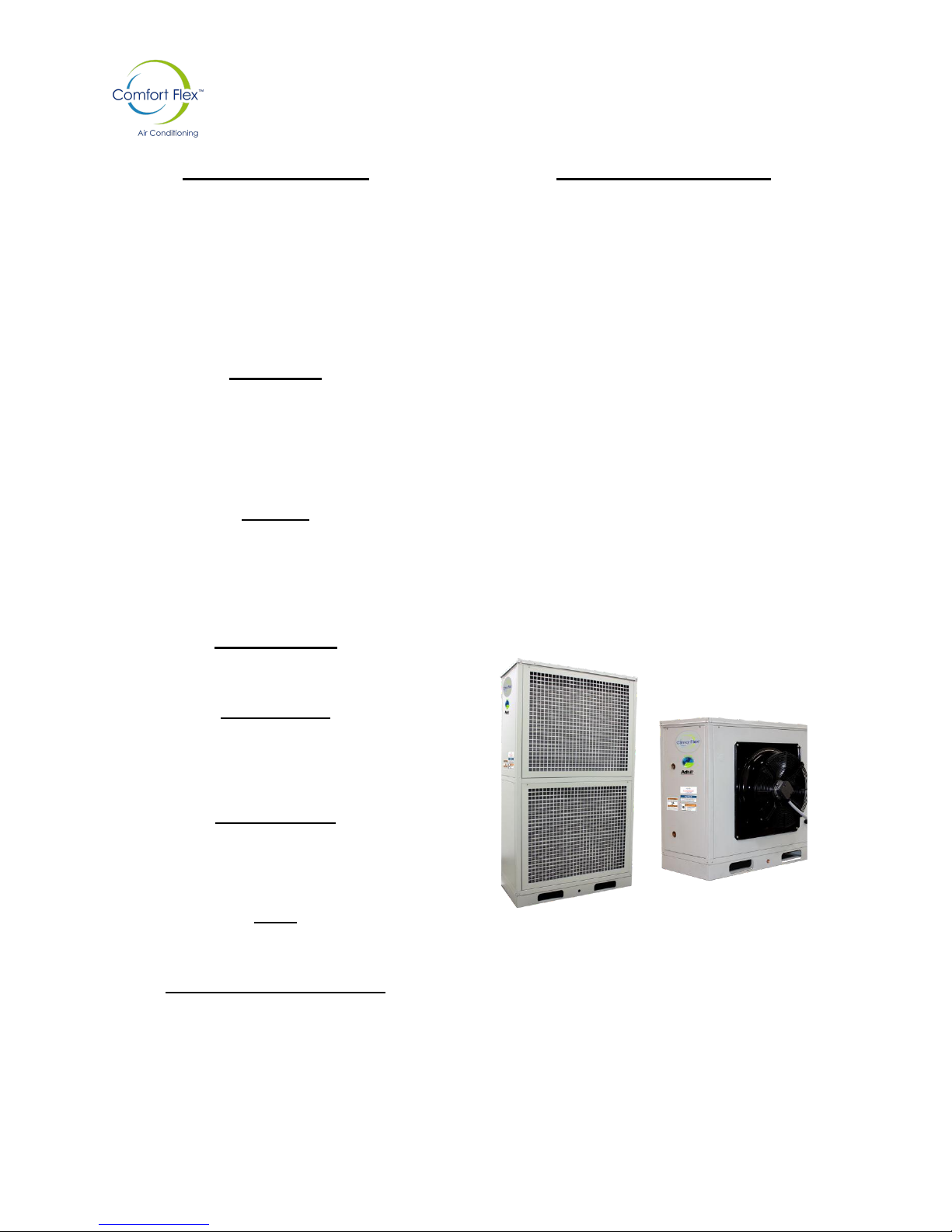
Comfort Flex chiller units are built with control and design in
mind, assembled with technically specialized control
software. Some of our features are in house production of all
piping and wiring, scroll type compressors, new generation
evaporators, air cooled condensers, optional hydraulic
components, and several safety and security protections.
Our units are ecofriendly and operate with R-410A
refrigerant.
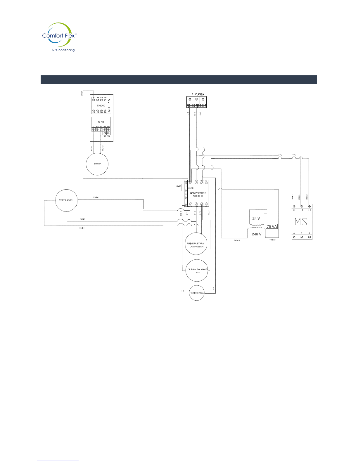
ELECTRICAL COMPONENTS
All units are equipped with a control panel, security anti-
theft devices, internal and external overheating protection,
compressor drive protection, flow protection, freezing
protection and electrical failure protection. The control
panel has LED operation indicating lights.
EQUIPMENT
Fully Factory assembled, and individually run tested with all
required piping, wiring, and controls for operation.
HYDRAULIC COMPONENTS (OPTIONAL)
WATER PUMP
The drive in the water pump is TEFC (Totally Enclosed
Fan Cooled) and has anti-corrosive coating on the
housing.
MODULE
Steel base, anti-corrosive painted steel panels. Easy Access
for maintenance without compromising the unit´s stability.
CONTROL
The control unit allows the connection of the unit to the
INTERNET, and allows the user to visualize all the unit’s
operating information, such as variable graphics, tendencies
cycle time, diagnosis of components, alarms, etc. Access to
this information renders a more efficient operation and
system control.
COMPRESSORS
Two stage Scroll type hermetic compressors.
CONDENSERS
High efficiency microchannel with optional anti-corrosive
coating.
EVAPORATORS
Compact Plate Heat exchangers with thermally isolated
hydraulic refrigerant pipes and connections.
FANS
Low vibration and noise Axial Fans.
REFRIGERATION CONTROLS
The units are equipped with solenoid valves, expansion
valves, dehydrator, and service valves.

Comfort Flex
Rev: February 5th 2016
1.1 ADVANTAGES OF CLIV SERIES CHILLER UNITS
NEW CLIV MODELS
EFFICIENCY
Comfort Flex water chillers are designed to comply with all requirements on all commercial projects. Air
cooled CLIV-Comfort Flex units may be applied in many ways; the units can be installed as stand alone
or in any number combination to get the exact required capacity for the project demands. The operation
allows modulating in accordance with the building thermal load variations, and achieving the desired
temperature in a precise and fast manner with high efficiency and minimum energy consumption.
CLIV Comfort Flex unit capacity ranges from 3 to 5 Tons.
OPERATION
CLIV Comfort Flex units have reduced vibration levels making them virtually silent. The overall design
allows for easy, fast, and low price installation.
QUALITY
Each unit is carefully manufactured and individually tested under strict international standards. CLIV
Comfort Flex units have state of the art components that offer a high quality product.
ENVIRONMENTALLY FRIENDLY
Comfort Flex units use R-410A refrigerant to reduce operating costs, and contribute to a significant
reduction of CO2 emissions. We are ecofriendly and strive to make green quality products.
6,8 and 10 tons.
3 and 5 tons.

Comfort Flex
Rev: February 5th 2016
1.2 COMFORT FLEX INSTALLATION DIAGRAM

Comfort Flex
Rev: February 5th 2016
2. NOMENCLATURE
CLIV
ACC
60,000
A
3
S
1
2
3
4
5
6
1 SERIE
CLIV
Air cooled bank type module
2 TYPE
ACC
Air Cooled Cooling Only
ACH
Air Cooled heat-pump
3 NOMINAL CAPACITY
036
36,000 BTU/HR
061
61,000 BTU/HR
072
72,000 BTU/HR
096
96,000 BTU/HR
120
120,000 BTU/HR
4 FAN
A
Axial
5 VOLTAGE
3
220/3/60
2
440/3/60
6 COMPRESSORS
S
Two Stage
F
Fixed

Comfort Flex
Rev: February 5th 2016
3. Technical Specs
COOL ONLY

Comfort Flex
Rev: February 5th 2016
HEAT PUMP

Comfort Flex
Rev: February 5th 2016
4. ELECTRICAL DIAGRAM
CONTROL DIAGRAM CLIV-ACC-036-A3S, CLIV-ACC-060-A3S

Comfort Flex
Rev: February 5th 2016
ELECTRICAL DIAGRAM CLIV-ACC-036-A3F, CLIV-ACC-060-A3F

Comfort Flex
Rev: February 5th 2016
CONTROL DIAGRAM CLIV-ACC-072-A3F, CLIV-ACC-096-A3F, CLIV-ACC-120-A3F

Comfort Flex
Rev: February 5th 2016
ELECTRICAL DIAGRAM CLIV-ACC-072-A3F, CLIV-ACC-096-A3F, CLIV-ACC-120-A3F

Comfort Flex
Rev: February 5th 2016
6. DIMENSIONS

Comfort Flex
Rev: February 5th 2016
6.1 DIMENSIONS

Comfort Flex
Rev: February 5th 2016
Startup Manual
CLIV Series

Comfort Flex
Rev: February 5th 2016
1. UNIT INSTALLATION AND STARTUP
a. INSTALLATION
/!\ WARNING /!\
To keep warranty this unit must be
installed by trained personnel with
expertise on water chillers installation.
Some of the voltages on the unit may be
dangerous, before servicing it is
recommended to totally de-energize the
unit.
LOCATION
CLIV Units are designed to be installed in interiors. It
is necessary that the unit has air venting, and a free air
intake (see Fig 1) to allow for good air circulation and
allow access for maintenance.
For fully functioning, CLIV units only require the
connection with the hydraulic local net and power
supply connection in accordance with technical data
sheet.
Fig. 1

Comfort Flex
Rev: February 5th 2016
MODELS
DIMENSIONS
A
B
Cm
in
cm
in
CLIV
100
39.5
60
23.6
1.1. INSTALLATION
The following items must be checked before the unit´s startup.
UNIT MODEL:
SERIAL NUMBER:
The following procedures are to be considered by the installer; their
personnel must be qualified, and certified to perform installation in
order to comply all specifications and good practices to assure the
correct unit´s operation.
1.- PHYSICAL INSPECTION (BEFORE ELECTRICAL CONNECTION)
Check unit for possible transportation or handling damage.
Visual check for refrigerant leaks.
Only Open unit to install system piping. Do not remove connection´s protection until hydraulic
circuit is to be closed.
Check for foreign objects in fan discharge.
Check pulley alignment, and band tension.
DATE:
JOB SITE:
LOCATION:
CONTRACTOR:
TECHNICIAN / COMPANY THAT
PERFORMS STARTUP:

Comfort Flex
Rev: February 5th 2016
Check that air intake is not obstructed, and has the required space suggested on Fig. 1
2.- HYDRAULIC CIRCUIT INSPECTION
Water connections are NPT type inner thread (to identify the connection diameter, see unit’s data
sheet). The installation of a water filter is necessary on all hydraulic circuits in order to avoid solid
particles in it, which must be installed on the return side of the circuit, and cleaned once the system´s
initial charge is finished.
Check water filter to be clean.
Verify that all service valves are open.
Check for adequate makeup water supply.
Verify that all piping is filled with water and air has been vented out.
Check Thermometers.
Check Manometers.
Note: Accessories such as Thermometers, manometers, measuring ports, etc. are recommended but
not necessary for the unit´s operation.
/!\ WARNING /!\ If hydraulic circuit contains air, it may compromise the units operation.
1.2. PREVIOUS TO STARTUP CHECKLIST
The following items must be checked, and written on a report, before unit´s startup.
UNIT MODEL:
UNIT SERIAL NÚMBER:
DATE:
JOBSITE:
LOCATION:
INSTALLER CONTRACTOR:
TECHNICIAN / COMPAÑY STARTING THE UNIT:

Comfort Flex
Rev: February 5th 2016
The following procedures are to be considered by the installer; their
personnel must be qualified, and certified to perform installation in
order to comply all specifications and good practices to assure the
correct unit´s operation.
1.- PHYSICAL INSPECTION (BEFORE ELECTRICAL CONNECTION)
Check unit for possible transportation or handling damage.
Visually check for refrigerant leaks.
Only Open unit to install system piping. Do not remove connection´s protection until
hydraulic circuit is to be closed.
Check for foreign objects in fan discharge.
Check pulley alignment, and band tension.
Check that air intake is not obstructed and has the required space suggested on Fig. 1
1.- HYDRAULIC CIRCUIT INSPECTION
Water connections are NPT type inner thread (to identify the connection diameter, see unit’s data
sheet). The installation of a water filter is necessary on all hydraulic circuits in order to avoid solid
particles in it, which must be installed on the return side of the circuit, and cleaned once the system´s
initial charge is finished.
Check water filter to be clean.
Verify that all service valves are open.
Check for adequate makeup water supply.
Verify that all piping is water full and air has been vented out.
Check Thermometers.
Check Manometers.
Note: Accessories such as Thermometers, manometers, measuring ports, etc. are recommended but not
necessary for the unit´s operation.
WARNING! If hydraulic circuit contains air, it may compromise the units operation.
1.2.1. ELECTRICAL SUPPLY INSPECTION
The electrical piping are nipple NPT threaded conduit (1” inch diameter on all models) the units require 3
phase grounded electrical power.
Verify that the thermo-magnetic switch is of correct capacity for the unit.

Comfort Flex
Rev: February 5th 2016
Check that all electrical connections are tight.
Check for false contacts on ground, and all wiring.
Check internal connections for control and power.
Measure voltage on all lines, and ground, neutral, and TF line.
Check for overload protection on motors to be in position to design requirements, and
on automatic mode.
Check voltage monitor control (*Motor Saver), to be adjusted to supply the correct
power voltage for the unit.
Note: The unit´s control panel has a ventilation duct, and it must not be obstructed in any manner.
*The unbalance percentage of electrical supply should
be calculated with the following formula and adjusted
on the UNBALANCE TRIP knob.
UNBALANCE PORCENTAGE = [(MAXIM AVERAGE
DEVIATION)/(AVERAGE)]X[100]
Note: Comfort Flex units are previously factory
adjusted however the electrical supply may vary on
each installation, and due to this unbalance must be
adjusted before startup in order to protect all the unit´s
motors and electrical components.
DIAGNOSIS INDICATING LIGHTS (LED STATUS)
NORMAL
OPERATION
CONSTANT GREEN
START DELAY
INTEMITENT GREEN
INVERTED
PHASE
INTERMITENT RED
PHASE
UNBALANCED
RED ON LAPSES
HIGH / LOW
CONSTANT RED
This manual suits for next models
6
Table of contents
Popular Chiller manuals by other brands

Carrier
Carrier AQUAFORCE 30XA080-500 installation instructions

AIREDALE
AIREDALE LogiCool LCC20 Technical manual

SMC Networks
SMC Networks HRS-R Series Operation manual

Lauda
Lauda ULTRACOOL UC 8 manual

Parker
Parker Hyperchill Plus user manual

Daikin
Daikin EWWD VZ Installation, maintenance and operating manual