COMINOX STERILCLAVE 18 User manual

SERVICE MANUAL
-Steam Steriliser-
FOREWORD
This manual IS NOT an integral part of the steriliser.
The manual is addressed to qualified, specialised technicians for routine maintenance
and repairs.
Technicians or operators mused be authorised in writing by COMINOX.
Technicians must read this manual and follow the instructions herein contained. COMINOX
is not liable for any injury and/or damage to people or property or to the steriliser itself
should the conditions herein illustrated be disregarded.
This manual contains industrial secrets which must not be disclosed. The manual and its
annexes must not be edited, modified, copied or given to third parties unless authorised
by COMINOX.

2

3
CONTENTS
CONTENTS ........................................................................................................................................ 3
Reference list.................................................................................................................................... 5
Graphical reference representation Model 6 S Dynamica ..................................................... 6
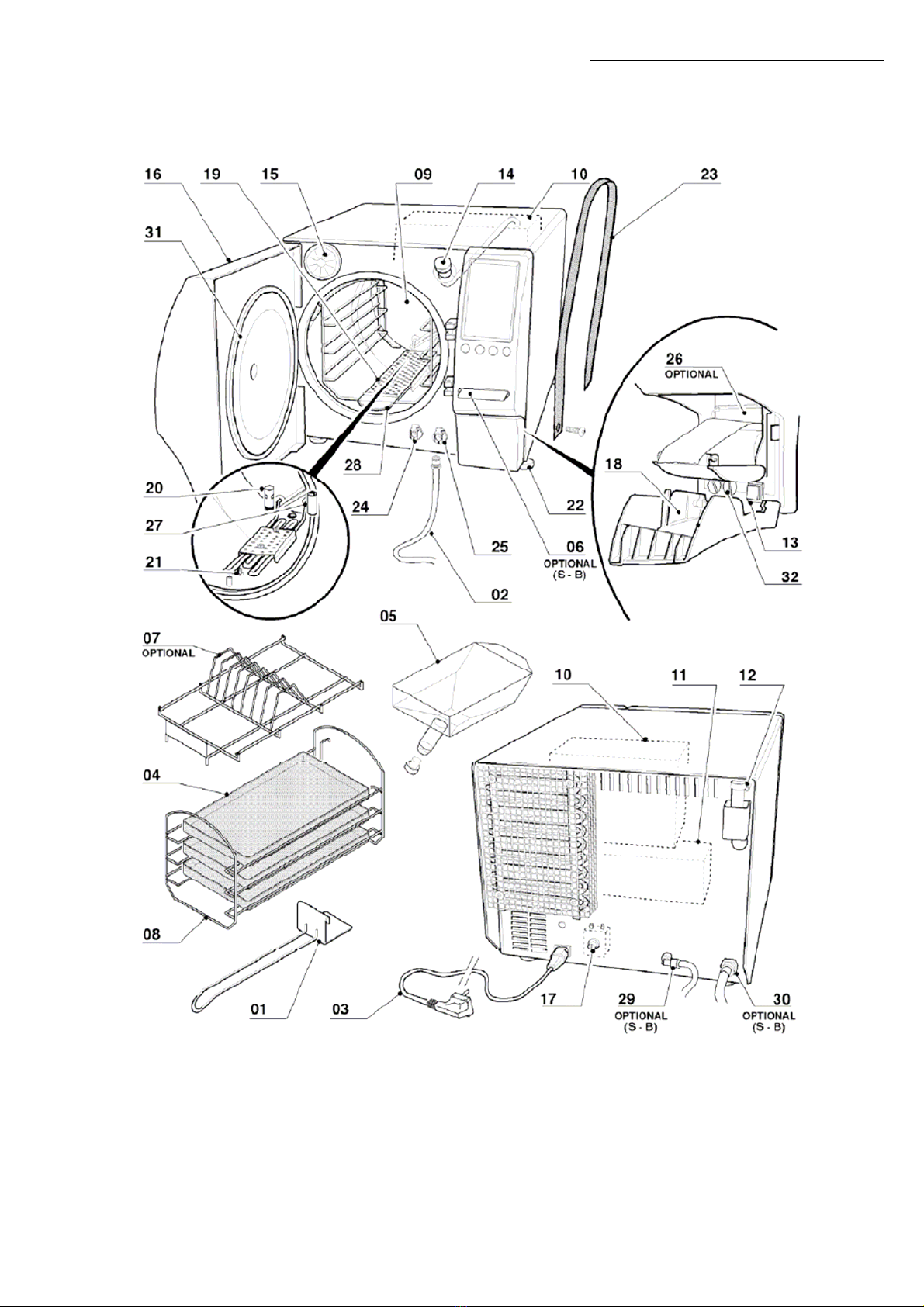
Graphical reference representation Model 18.......................................................................... 7
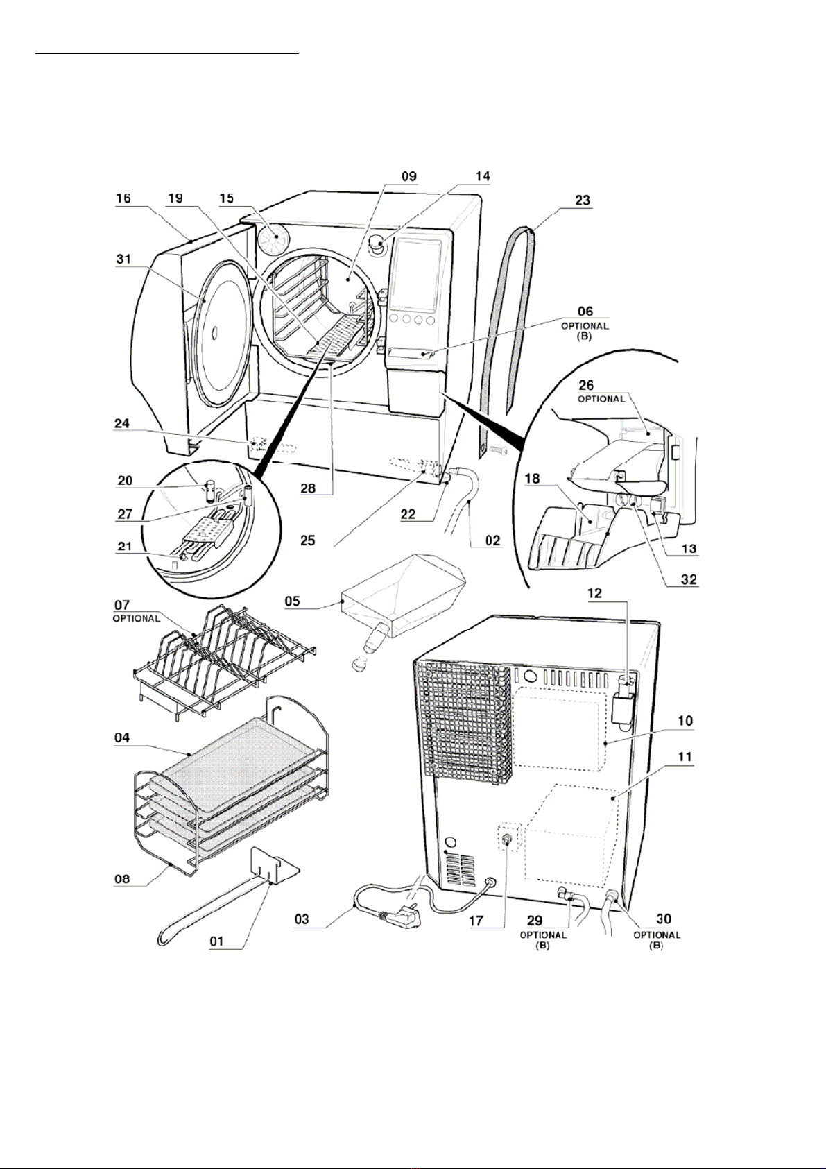
Graphical reference representation Model 24.......................................................................... 8
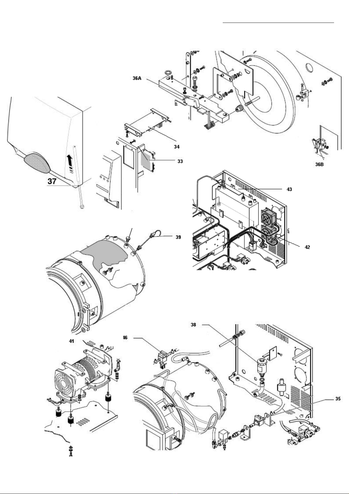
Graphical reference representation of common components ............................................. 9
TECHNICIAN MENU ....................................................................................................................... 11
Inputs ............................................................................................................................................... 13
Outputs............................................................................................................................................ 14
PT1 / PT2 / PT3 board calibration ................................................................................................ 15
TP board calibration...................................................................................................................... 18
PT1 / PT2 / PT3 probe calibration ................................................................................................ 20
PT1 / PT2 / PT3 correction ............................................................................................................. 20
Continuous cycle........................................................................................................................... 21
Security code ................................................................................................................................. 21
Chamber load test........................................................................................................................ 22
Accessories ..................................................................................................................................... 23
Delete maintenance .................................................................................................................... 23
Simplified version of the Technician Menu (PUCK) ................................................................... 24
MAINTENANCE .............................................................................................................................. 25
Items................................................................................................................................................. 25
Save maintenance ....................................................................................................................... 26
Scheduled service table.............................................................................................................. 27
MESSAGES...................................................................................................................................... 28
Scheduled maintenance............................................................................................................. 28
Check water quality ..................................................................................................................... 28
Drain waste water ......................................................................................................................... 28
Cooling pause................................................................................................................................ 30
ALARMS.......................................................................................................................................... 31
Insufficient water quality alarm................................................................................................... 31
Insufficient water level alarm....................................................................................................... 31
Chamber level alarm.................................................................................................................... 32
Insufficient steam alarm ............................................................................................................... 33
Pressurisation alarm ....................................................................................................................... 34
Overtemperature alarm............................................................................................................... 34
Insufficient vacuum alarm ........................................................................................................... 34
Fractioned vacuum alarm........................................................................................................... 34
Sterilisation temperature band alarm: overtemperature / undertemperature ................. 35
Level probe alarm ......................................................................................................................... 36
Coil alarm........................................................................................................................................ 36
Self-filling alarm .............................................................................................................................. 37
Contents

4
Door alarm...................................................................................................................................... 38
PT1 temperature probe alarm..................................................................................................... 39
Drain alarm ..................................................................................................................................... 39
Misalignment alarm....................................................................................................................... 39
Pressure transducer alarm............................................................................................................ 40
Manual stop alarm ........................................................................................................................ 40
Power missing alarm...................................................................................................................... 40
Event alarm..................................................................................................................................... 40
Alarm code list.............................................................................................................................. 41
ADDITIONAL CHECKS AND SETTINGS........................................................................................... 42
Display off or not clear.................................................................................................................. 42
Level probe check ........................................................................................................................ 42
Safety valve check ....................................................................................................................... 43
Door adjustment ............................................................................................................................ 44
Pressure rises too slowly................................................................................................................. 45
Poor drying...................................................................................................................................... 45
Steam leakage from the safety valve ....................................................................................... 45
Vacuum pump servicing procedure ......................................................................................... 46
Water automatic inlet does not work correctly ....................................................................... 48
The printer does not print ............................................................................................................. 48
AUTOMATIC WATER INLET AND DIRECT DRAIN SYSTEM INSTALLATION ..................................... 49
INSTALLATION OF THE SPEEDY WATER DEMINERALIZATION SYSTEM .......................................... 51
STERILCARD READER INSTALLATION ............................................................................................. 54
PRINTER INSTALLATION .................................................................................................................. 56
FIRMWARE UPGRADE..................................................................................................................... 59
DIAGRAMS AND WIRINGS ............................................................................................................60
Logic electronic board................................................................................................................. 60
Electronic power board ............................................................................................................... 61
Wiring diagram - 18/24 S - B - BHD .............................................................................................. 64
Wiring diagram 6 S Dynamica..................................................................................................... 65
Wiring diagram - 18 S Dynamica ................................................................................................ 66
Hydraulic diagram 18/24 S - B - BHD .......................................................................................... 67
Hydraulic diagram 6/18 S Dynamica......................................................................................... 68
STEAM PEAK diagram.................................................................................................................... 69
p>1,2 bar VACUUM PULSE diagram ........................................................................................... 70
p<=1,2 bar VACUUM PULSE diagram ......................................................................................... 71
DRYING diagram ........................................................................................................................... 72
APPENDIX 1: 18/24 CYCLE SET POINTS ........................................................................................ 73
APPENDIX 2: COLDEST AND WARMEST POINT DEFINITION ......................................................... 74
Contents

5
Reference list
03, Power cable
05, Measuring funnel
06, SterilCard
08, Tray support
09, Chamber
10, Clean water tank
11, Waste water recovery tank
12, Safety valve
13, Main switch
14, Filler
15, Air sterilisation filter
16, Door
17, Safety thermostat
18, Door
19, Coil grid
20, Drain filter
21, Chamber probe
24, Clean water drain tap
25, Waste water drain tap
26, Printer
29, Automatic water inlet
30, Direct drain
31, Chamber seal
32, Fuses
33, Logic board
34, Power board
35, Water inlet pump
36A, Micro-switch M1
36B, Micro-switch M2
37, Unlocking tool
38, Transducer
39, Chamber temperature probe
40, Inspection plugs
41, Vacuum pump
42, Fans
43, Level probes
46, Automatic water inlet pump
Contents

6
Graphical reference representation Model 6 S Dynamica
Contents

7
Graphical reference representation Model 18
Contents

8
Graphical reference representation Model 24
Contents

9
Graphical reference representation of common components
40
Contents

10

11
TECHNICIAN MENU
Insert the Technician’s SterilCard to access the Technician Menu.
If the steriliser is not equipped with a SterilCard reader, a Technician’s SterilCard kit may be
employed. The kit includes a reader, a Technician’s SterilCard and a cable for connecting
the reader to logic board 33 (connector J5).
In STAND BY mode, press MENU and use the ↑↓ arrows to select the Technician Menu
(option 6):
Press ENTER to open the Technician Menu:
Technician Menu

12
Use the ↑↓ arrows to scroll the list and highlight the required option. Press ENTER to access
the selected option.
Press to go back to the MENU page.
Technician Menu

13
Inputs
The status of the steriliser inputs can be displayed:
• S1 is the clean water tank 10 safety probe
• S2 is the clean water tank 10 minimum level probe
• S3 is the clean water tank 10 maximum level probe
• S4 is the waste water recovery tank 11 maximum level probe (not used in
6/18 S Dynamica models)
• S5 is the chamber 09 level probe for models 18/24 S Dynamica - S - B – BHD
(not used in 6 S Dynamica model)
• S6 is not used
• S7 is not used
• PT1 is the temperature probe 39 in chamber 09
• PT2 is not used
• PT3 is not used
• Pressure transducer 38
• Conductivity meter (optional; standard on BHD models)
• Micro-switch M1 36A: door locked
• Micro-switch M2 36B: door pre-lock
Use the ↑↓ arrows to scroll the list and press to go back to the Technician Menu.
Technician MenuTechnician Menu

14
Outputs
The status of the steriliser outputs can be displayed and modified:
• EV1 charge to which the water inlet pump 35 is connected in parallel
(included on all models)
• EV2 drain (included on all models)
• EV3 3-way (not included on 6/18 S Dynamica models)
• EV4 steam (not included)
• EV5 drying (not included on 6/18 S Dynamica models)
• EV6 by-pass (not included on 6/18 S Dynamica models)
• Water pump is the automatic water inlet pump 46 (optional; standard on
BHD models). If the steriliser is provided with connections to the SPEEDY
WATER demineralisation system, the pump is replaced by solenoid valve EV7
(see page 51)
• Vacuum pump (not included on 6/18 S Dynamica models)
• Door lock (included on all models)
• The fan(s) are fans 42: single on 6/18 S Dynamica and 18 S; double on other
models
• Aux 1 is not used
• Aux 2 is not used
• External coil for pre-heating and drying chamber 09
• Internal coil for steam generation
NB. The internal coil is:
• The external cylindrical band arranged around chamber 09 in models 18 S
Dynamica, 18/24 S - B - BHD
• The series of lower and upper coils external to chamber 09 in 6 S Dynamica
The internal coil is:
• The coil in chamber 09 in models 18 S Dynamica, 18/24 S - B - BHD
• The lower coil external to chamber 09 in 6 S Dynamica
Use the ↑↓ arrows to scroll the list and highlight the required option. Press ENTER to change
the output state (ON/OFF).
Press to go back to the Technician Menu.
Technician Menu

15
PT1 / PT2 / PT3 board calibration
This procedure is used to calibrate temperature probe PT1, PT2 and PT3. A specific
calibration kit is needed for calibration:
To calibrate PT1, PT2 or PT3 press option 3, 4 or 5 respectively in the Technician Menu:
CN2
CN1
CN3
CN4 0-5V switch
Technician Menu

16
Disconnect the connector corresponding to the temperature probe you want to calibrate
from the electronic power board 34: disconnect connector CN12 for sensor PT1,
connector CN13 for sensor PT2 or connector CN14 for sensor PT3.
Using the cable included in the kit, connect connector CN1 of the calibration tool (which
corresponds to a 1000 Ohm sample coil, corresponding to 0°C) to connector CN12, CN13
or CN14 of the power board 34:
Wait for at least 10 seconds and press ENTER.
Technician Menu

17
Disconnect the cable from connector CN1 of the calibration tool and connect connector
CN2 of the calibration tool (1573 Ohm sample coil, corresponding to 150°C) to calibrate
the sensor PT1 or the connector CN3 (1832 Ohm sample coil, corresponding to 220°C) to
calibrate sensors PT2 and PT3.
Wait for at least 10 seconds and press ENTER.
Press to go back to the Technician Menu without changing the calibration.
Technician Menu

18
TP board calibration
This procedure is used to calibrate the pressure transducer:
Disconnect the connector CN11 corresponding to the pressure transducer from the
electronic power board 34:
Technician Menu

19
Using the cable included in the kit, connect connector CN4 of the calibration tool to
connector CN11 of the power board 34.
Set the calibration tool switch to 0 Vdc.
Wait for at least 10 seconds and press ENTER.
Now set the calibration tool switch to 5 Vdc.
Wait for at least 10 seconds and press ENTER.
Press to go back to the Technician Menu without changing the calibration.
Technician Menu

20
PT1 / PT2 / PT3 probe calibration
This procedure is used to complete the calibration of the temperature probes PT1, PT2 and
PT3. This operation must be performed whenever a temperature probe is replaced.
Press +/- to enter a 0°C value of the temperature probe shown on the label or on the wire
sheath (e.g.: if a value of 1000.2 is shown on the PT1 sensor label, press + twice to display
1000.2). Press ENTER to confirm.
Press to go back to the Technician Menu without changing the calibration.
PT1 / PT2 / PT3 correction
This procedure is used to correct the temperature value displayed during the sterilising
process. For example, if using an external sampling tool a temperature lower than the one
displayed is measured in the chamber during the sterilisation process, the temperature
may be corrected as follows:
Press +/- to enter the correction which will change the temperature shown on the display.
Press ENTER to confirm.
Press to go back to the Technician Menu without changing the correction.
Technician Menu
This manual suits for next models
9
Table of contents