Commell CMB-37E User manual

CMB-37E
Mini Barebone system
Intel High Performance Platform
Installation Guide
Edition 1.11
2017/10/17

CMB-37E User’s Manual
-1-
Copyright
Copyright 2016, all rights reserved. This document is copyrighted and all rights are reserved.
The information in this document is subject to change without prior notice to make
improvements to the products.
This document contains proprietary information and protected by copyright. No part of this
document may be reproduced, copied, or translated in any form or any means without prior
written permission of the manufacturer.
All trademarks and/or registered trademarks contains in this document are property of their
respective owners. Disclaimer
The company shall not be liable for any incidental or consequential damages resulting from
the performance or use of this product.
The company does not issue a warranty of any kind, express or implied, including without
limitation implied warranties of merchantability or fitness for a particular purpose.
The company has the right to revise the manual or include changes in the specifications of
the product described within it at any time without notice and without obligation to notify any
person of such revision or changes.
Trademark
All trademarks are the property of their respective holders.
Any questions please visit our website at TUhttp://www.commell.com.twUT

CMB-37E User’s Manual
-2-
Index
Chapter 1 <Packing List>................................................. 4
Chapter 2 <Product Specification>................................... 5
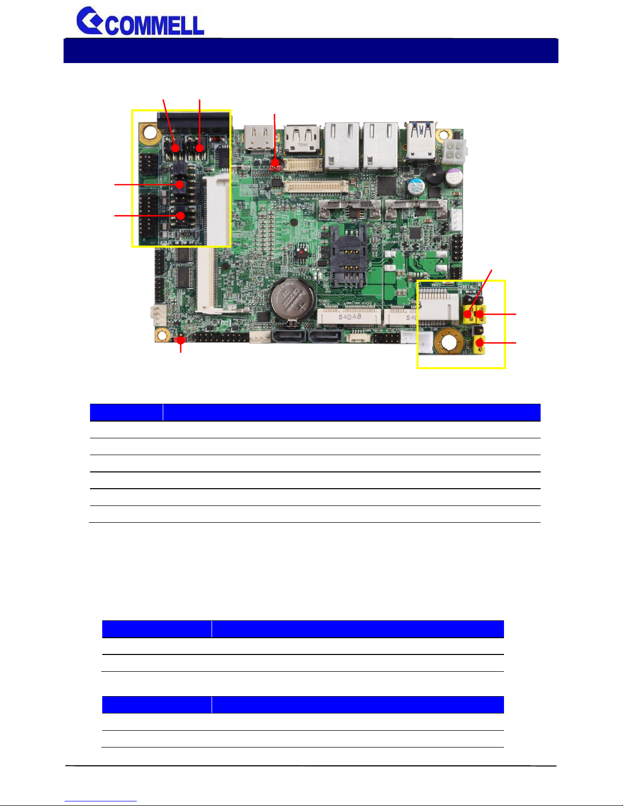
2.1 <Motherboard Placement>........................................................5
2.1.1 <Internal connectors list>....................................................6
2.1.2 <External connectors list>...................................................6
2.2 <Jumper Location and Reference>..........................................7
2.2.1 <Jumper list>.......................................................................7
2.2.2 <Clear CMOS and Power on type selection> .....................7
2.3 <Motherboard I/O interface>.....................................................8
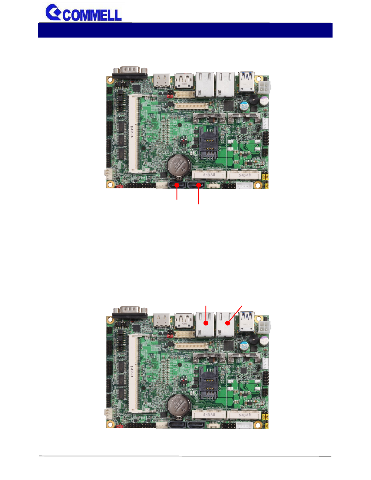
2.3.1 <Serial ATA interface> ........................................................8
2.3.2 <Ethernet interface>............................................................8
2.3.3 <Display interface>.............................................................9
2.3.4 <Serial Port interface>.......................................................10
2.3.5 <USB interface>................................................................11
2.3.6 <Audio interface>..............................................................11
2.3.7 <Expansion slot>...............................................................12
2.3.8 <Front panel switch and indicator>...................................13
2.4 <Power supply>.........................................................................14
2.4.1 <Power input>...................................................................14
2.4.2 <Power output>.................................................................14
2.5 <I/O Panel>................................................................................15
2.5.1 <Front>..............................................................................15
2.5.2 <Rear>...............................................................................16
Chapter 3< Hardware Installation>................................. 17
3.1<Chassis Setup Procedure> ....................................................17
3.1.1<Memory Setup>................................................................19
3.1.2<HDD Setup>.....................................................................21

CMB-37E User’s Manual
-3-
Appendix A <Install Desk/Wall mount>........................... 27
Appendix B <Install VESA mount>................................. 29
Contact information .........................................................................34

CMB-37E User’s Manual
-4-
Document Content:
Chapter 1: Packing List
Chapter 2: Product Specification
Chapter 3: Hardware Installation
Chapter 1 <Packing List>
CMB-37E Chassis x 1
(Including LE-37E Motherboard)
a.
b.
SATA Cable x 1
(OALSATA-90L12)
c.
SATA Power Cable x 1
(OALSATA15-1PS)
g.
CD Driver x 1
d.
e.
Desk/Wall mount x 1 (pair)
AC-DC Adapter x 1
(DSPD-084-12-VI)
VESA mount x 1 (Optional)
f.

CMB-37E User’s Manual
-5-
Chapter 2 <Product Specification>
2.1 <Motherboard Placement>
CN_LVDS
MINI_CARD1
CN_AUDIO
DC_IN
CN_USB1
JFRNT
SATA3-2
DC_OUT
MINI_CARD2
1
SO-DIMM
SATA3-1
CN_USB2
COM1
HDMI
DisplayPort
LAN1
LAN2
USB
SIMM

CMB-37E User’s Manual
-6-
2.1.1 <Internal connectors list>
Connector
Function
SO-DIMM
204-pin DDR3L SO-DIMM slot
SATA3-1/2
7-pin Serial ATA3 connector
CN_AUDIO
5 x 2-pin audio pin header
CN_USB1/2
5 x 2-pin USB2.0 pin header
SIMM
6-pin SIM card slot
JFRNT
5 x 2-pin front panel switch/indicator pin header
MINI_CARD1/2
52-pin MiniPCIe card slot
DC_OUT
4-pin SATA Power connector
DC_IN
4-pin ATX12V power connector
2.1.2 <External connectors list>
Connector
Function
COM1
DB9 connector
DisplayPort
DisplayPort connector
HDMI
HDMI connector
USB
2 x USB3.0 connector
LAN1
RJ45 connector
LAN2
RJ45 connector

CMB-37E User’s Manual
-7-
2.2 <Jumper Location and Reference>
2.2.1 <Jumper list>
Jumper
Function
JAT
Power mode select
JRTC
CMOS Normal/Clear Setting
JVLCD
Panel Voltage Setting
JMSATA1/2
MiniCard1/2 mSATA Setting
JCSEL1/2
CN_COM2 RS232/422/485 select
JP1/2
COM1 and CN_COM2 9-pin setting
2.2.2 <Clear CMOS and Power on type selection>
JRTC: Clear CMOS data jumper
Jumper settings
Function
1-2
Clear CMOS
2-3
Normal (Default)
JAT: AT/ATX mode select jumper
Jumper settings
Function
1-2
AT mode
2-3
ATX mode (Default)
JRTC
JVLCD
JMSATA2
JAT
JMSATA1
JP2
JP1
JCSEL1
JCSEL2

CMB-37E User’s Manual
-8-
2.3 <Motherboard I/O interface>
2.3.1 <Serial ATA interface>
Support RAID0 and 1.
2.3.2 <Ethernet interface>
The board provide I210-AT and I218-LM Gigabit Ethernet which supports WOL on
rear I/O.
It supports Intel® AMT 10.0 feature.
(Note that the CPU must support vPro technology, ex: i7-5650U)
I218-LM
SATA3-1
SATA3-2
I210-AT

CMB-37E User’s Manual
-9-
2.3.3 <Display interface>
Based on the 5th/4th Gen CPU with built-in HD Graphics, the DisplayPort up to
3840x2160 @ 60Hz, the HDMI resolution up to 2560x1600 @ 60Hz
DisplayPort
HDMI

CMB-37E User’s Manual
-10-
2.3.4 <Serial Port interface>
COM1: RS232 DB9 connector
Pin
Signal
Pin
Signal
1
DCD
2
RXD
3
TXD
4
DTR
5
GND
6
DSR
7
RTS
8
CTS
9
Set by JP2
10
Key
JP2: COM1 pin-9 setting
Jumper settings
Function
1-2
5V
3-4
12V
5-6
RI (Default)
Effective patterns of connection: 1-2 / 3-4 / 5-6
Other may cause damage
JP2
2
6
1
5
COM1

CMB-37E User’s Manual
-11-
2.3.5 <USB interface>
CN_USB1/2: Front panel USB2.0 10-pin header (Pitch 2.54mm)
Pin
Signal
Pin
Signal
1
5VSB
2
5VSB
3
DATA0-
4
DATA1-
5
DATA0+
6
DATA1+
7
GND
8
GND
9
GND
10
Key
2.3.6 <Audio interface>
CN_AUDIO
2
9
CN_USB1
1
10
10
2
9
USB3.0
1
CN_USB2
1
2
9
10

CMB-37E User’s Manual
-12-
CN_AUDIO: Front panel audio 10-pin header (Pitch 1.27mm x 2.54mm)
Pin
Signal
Pin
Signal
1
MIC_L
2
GND
3
MIC_R
4
NC
5
FP_OUT_R
6
MIC_DETECT
7
SENSE
8
Key
9
FP_OUT_L
10
FP_OUT_DETECT
2.3.7 <Expansion slot>
MINI_CARD1/2 supports mSATA set by JMSATA1/2.
MINI_CARD1 supports SIM card to use 3G module.
JMSATA1/2: Setting MINI_CARD1/2 to support PCIe or mSATA
Jumper settings
Function
1-2
Support mSATA
2-3
Normal operation
(Default Setting to PCIe)
Note: JMSATA1 for setting MINI_CARD1, JMSATA2 for setting MINI_CARD2
MINI_CARD1
JMSATA1
MINI_CARD2
1
3
1
3
JMSATA2

CMB-37E User’s Manual
-13-
2.3.8 <Front panel switch and indicator>
JFRNT: Front panel switch and indicator 14-pin header (Pitch 2.54mm)
Pin
Signal
Pin
Signal
1
Power_ON-
2
Power_ON+
3
Speaker-
4
Speaker+
5
HDD_LED-
6
HDD_LED+
7
Power_LED-
8
Power_LED+
9
Reset+
10
Reset-
JFRNT
2
9
10
1

CMB-37E User’s Manual
-14-
2.4 <Power supply>
2.4.1 <Power input>
DC_IN:ATX12V 4-pin power connector
Pin
Signal
Pin
Signal
1
GND
2
GND
3
9~24V Power input
4
9~24V Power input
2.4.2 <Power output>
DC_OUT: SATA power 4-pin connector
Pin
Signal
1
12V
2
GND
3
GND
4
5V
DC_IN
1
2
DC_OUT
1
4
3
4

CMB-37E User’s Manual
-15-
2.5 <I/O Panel>
2.5.1 <Front>
Line-out
Mic-in
USB2.0

CMB-37E User’s Manual
-16-
2.5.2 <Rear>
DC_IN
USB3.0
Power Button
COM
I218-LM
I210-AT
HDMI
DisplayPort

CMB-37E User’s Manual
-17-
Chapter 3< Hardware Installation>
3.1<Chassis Setup Procedure>
(a.) Screw off the chassis by the indication as below picture.

CMB-37E User’s Manual
-18-
(b.) Push the Chassis shield outward and open it.

CMB-37E User’s Manual
-19-
3.1.1<Memory Setup>
In the process, the system must be powered off.
a. Put the memory tilt into the slot. Note the Memory notch key aligned slot key.
b. Then press down till lock into the mounting notch.
c. To remove the memory, push outward on both sides of the latch.
Key
Mounting notch
Press down
Latch
Table of contents
Other Commell Desktop manuals