Commell LP-176 User manual

LP-176
Pico-ITX Motherboard
User’s Manual
Edition 1.5
2017/06/14

LP-176 User’s Manual
-1-
Copyright
Copyright 2016, all rights reserved. This document is copyrighted and all rights are reserved.
The information in this document is subject to change without prior notice to make
improvements to the products.
This document contains proprietary information and protected by copyright. No part of this
document may be reproduced, copied, or translated in any form or any means without prior
written permission of the manufacturer.
All trademarks and/or registered trademarks contains in this document are property of their
respective owners.
Disclaimer
The company shall not be liable for any incidental or consequential damages resulting from
the performance or use of this product.
The company does not issue a warranty of any kind, express or implied, including without
limitation implied warranties of merchantability or fitness for a particular purpose.
The company has the right to revise the manual or include changes in the specifications of
the product described within it at any time without notice and without obligation to notify any
person of such revision or changes.
Trademark
All trademarks are the property of their respective holders.
Any questions please visit our website at TUhttp://www.commell.com.twUT

LP-176 User’s Manual
-2-
Packing List:
Please check the package content before you starting using the board.
1 x LP-176 Motherboard
1 xDC Input Power Cable
(OALDC-B / 1040513)
+
_
1 x PS/2 Keyboard & Mouse cable
(OALPS2/KM / 1040131)
1 x Audio cable
(OALPJ-HDUNB / 1040123)
1 xUSB2.0 cable
(OALUSBA-3 / 1040173)
1 x Dual COM cable
(OALES-BKU2NB / 1040090)
1 x SATA Cable
(OALSATA22B-PM15SH15) / (1040512)
1 x Heatsink(Optional)
(OHS-176-01 / 2181110026)
1 x DDR3L SO-DIMM (Optional)
(DSDM4GB-DDR3L-1600-SO-1.35V / 1140091)
(DSDM8GB-DDR3L-1600-SO-1.35V / 1140092)
1 x Cooler fan (Optional)
(OHSF-176 / 2181010025)
1 x Driver CD
(Including User’s Manual)
1 x Heat spreader
(OHS-176 / 2181110015)

LP-176 User’s Manual
-3-
Index
Chapter 1 <Introduction> .................................................... 4
1.1 <Product Overview>............................................................ 4
1.2 <Product Specification> ......................................................5
1.3 <Mechanical Drawing>........................................................6
1.4 <Block Diagram>.................................................................8
Chapter 2 <Hardware setup> ............................................... 9
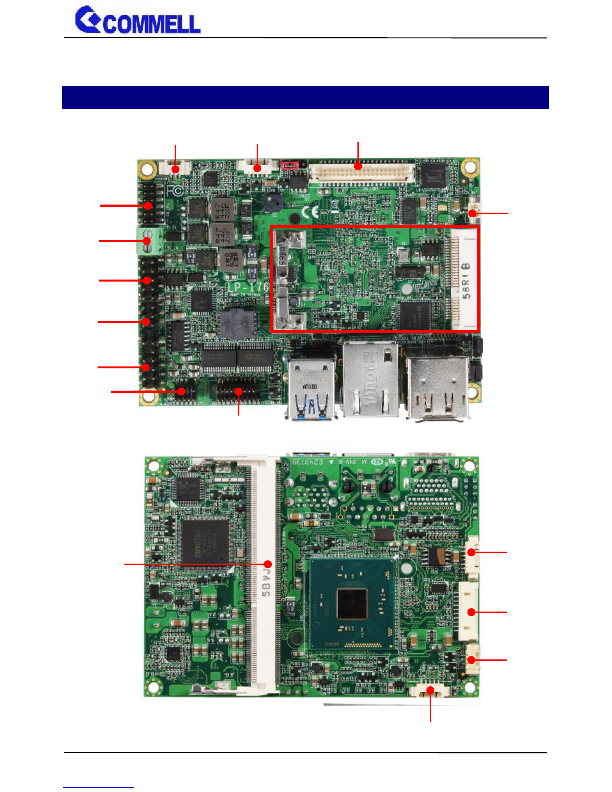
2.1 <Connector Location and Reference> ................................9
2.1.1 <Internal connectors list> ........................................10
2.1.2 <External connectors list>.......................................10
2.2 <Jumper Location and Reference> ................................... 11
2.2.1 <Jumper list> .......................................................... 11
2.2.2 <Clear CMOS and Power on type selection>.......... 11
2.3 <Installing the Memory>....................................................12
2.4 <I/O interface> ..................................................................13
2.4.1 <Serial ATA interface>.............................................13
2.4.2 <Ethernet interface>................................................13
2.4.3 <Display interface> .................................................13
2.4.4 <Serial Port interface> ............................................15
2.4.5 <USB interface>......................................................16
2.4.6 <Audio interface>....................................................16
2.4.7 <Expansion slot>.....................................................17
2.4.8 <Front panel switch and indicator> .........................18
2.4.9 <Other interface> ....................................................18
2.5 <Power supply> ................................................................20
2.5.1 <Power input>.........................................................20
2.5.2 <Power output>.......................................................21
Appendix A <Flash BIOS> ................................................. 22
A.1 BIOS Auto Flash Tool........................................................22
A.2 Flash Method....................................................................22
Appendix B <LCD Panel Type select> ................................. 24
Appendix C <Programmable Watch Dog Timer> .................. 25
Appendix D <Install Heat Spreader > .................................. 26
Appendix E <Setup ADP-3355> .......................................... 28
Contact information.......................................................... 29

LP-176 User’s Manual
-4-
Chapter 1 <Introduction>
1.1 <Product Overview>
LP-176 is pico Motherboard which is design based on Intel® Pentium® Processor N3000
Series Processor(Braswell SoC), delivering outstanding compute, graphical, and media
performance while operating in an extended range of thermal conditions. The SoC bases on
the Silvermont microarchitecture, utilizing Intel’s industry-leading 14nm process technology
with 3-D Tri-Gate transistors, which deliver significant improvements in computational
performance and energy efficiency.
New features
The Intel® Pentium® N3000 Series Processor and Atom™ x5 Processor Series have a
lower TDP 6W, it provides new HD Graphics to support triple display, 4K resolution,
maximum memory size is up to 8GB of DDR3L, and more enhanced security that is suitable
for a variety of intelligent systems the ideal choice.
All in One multimedia solution
The board provides high performance onboard graphics, 18/24-bit single/dual channel
LVDS interface, DisplayPort, HDMI, and High Definition Audio, to meet the very requirement
of the multimedia application.
Flexible Expansion Interface
The board provides one MiniPCIe and support mSATA.
Braswell remove EHCI, all USB ports are xHCI
When you install Windows7 with USB device(CDROM, Keyboard, Mouse...), Windows7 can
not identify your usb device. You can use SATA CD-ROM and PS/2 to install Windows7.

LP-176 User’s Manual
-5-
1.2 <Product Specification>
System
Processor
Intel® Braswell Series Processor N3710/X5-E8000,
FCBGA1170 package
Chipset
Braswell SoC
Memory
1 x DDR3L DIMM 1600 MHz up to 8GB,
Support Non-ECC, unbuffered memory only
Watchdog Timer
Generates a system reset with internal timer for 1min/s ~ 255min/s
Real Time Clock
Chipset integrated RTC with onboard lithium battery
Expansion
1 x MiniPCIe (support mSATA)
Graphics
Chipset
Intel® HD Graphics
Display Interface
1 x LVDS, 1 x HDMI, 1 x DisplayPort/VGA(Optional)
LAN
Chip
1 x Intel® I210-AT Gigabit LAN
I/O
Serial ATA
1 x SATA3
Audio
Realtek ALC262 HD Audio
Internal I/O
1 x SATA3, 2 x RS232, 2 x USB2.0, 1 x LPC, 1 x PS/2,
1 x SMBUS, 1 x LVDS, 1 x LCD inverter, 1 x Audio, 1 x VGA(Optional).
Rear I/O
2 x USB3.0, 1 x LAN, 1 x HDMI, 1 x DisplayPort(Optional).
Mechanical & Environmental
Power Requirement
DC INPUT 5V
Size & Thickness
100mm x 72mm (L x W)
Temperature
Operating within 0°C~60°C (32°F~140°F)
Storage within -20°C~80°C (-4°F~176°F)
Relative Humidity
10%~90%, non-condensing

LP-176 User’s Manual
-6-
1.3 <Mechanical Drawing>

LP-176 User’s Manual
-7-

LP-176 User’s Manual
-8-
1.4 <Block Diagram>
CPU
Braswell
SoC
DDR3L
SO-DIMM
1 x DisplayPort
1 x HDMI
PTN3460
1 x LVDS
SIO
NCT6102D
DDI
Channel A
eDP
DDI
1 x SATA3
SATA3
2 x USB3.0
2 x USB2.0
USB3.0
USB2.0
SPI Flash
SPI
PCIe x1
I210-AT
HDA
HD Audio
LPC
1 x LPC
ALC262
2 x RS232
1 x SMBUS
PCIe x1
SATA3
MiniPCIe
/ mSATA
1 x PS/2
SMBus

LP-176 User’s Manual
-9-
Chapter 2 <Hardware setup>
2.1 <Connector Location and Reference>
MINI_CARD
CN_USB
CN_PS2
JFRNT
5V_IN
CN_LPC
CN_LVDS
SYSFAN
CN_INV
SO-DIMM
5V_OUT
CN_AUDIO
CN_COM1/2
CN_BAT
CN_SATA
CPUFAN
SMBUS

LP-176 User’s Manual
-10-
2.1.1 <Internal connectors list>
Connector
Function
SO-DIMM
204-pin DDR3L SO-DIMM slot
CN_SATA
10-pin Serial ATA3 connector
CN_AUDIO
5 x 2-pin audio pin header
CN_LPC
6 x 2-pin LPC pin header
CN_LVDS
20 x 2-pin LVDS connector
CN_INV
5-pin LCD inverter connector
CN_SMBUS
5-pin SMBus connector
CN_COM 1/2
19-pin RS232 connector
CN_USB
5 x 2-pin USB2.0 pin header
CN_PS2
5 x 2-pin PS/2 pin header
CPUFAN
3-pin CPU fan connector
SYSFAN
3-pin system fan connector
JFRNT
5 x 2-pin front panel switch/indicator pin header
MINI_CARD
52-pin MiniPCIe card slot
5V_OUT
6-pin SATA Power connector
5V_IN
2-pin power input Terminal Block (5V Only)
2.1.2 <External connectors list>
Connector
Function
DisplayPort
DisplayPort connector
HDMI
HDMI connector
USB3
2 x USB3.0 connector
RJ45
RJ45 LAN connector
USB3.0
RJ45
DisplayPort
HDMI

LP-176 User’s Manual
-11-
2.2 <Jumper Location and Reference>
2.2.1 <Jumper list>
Jumper
Function
JAT
Power mode select
JRTC
CMOS Normal/Clear Setting
JVLCD
Panel Voltage Setting
JMSATA
MiniCard mSATA Setting
2.2.2 <Clear CMOS and Power on type selection>
JRTC: Clear CMOS data jumper
Jumper settings
Function
1-2
Clear CMOS
2-3
Normal (Default)
JAT: AT/ATX mode select jumper
Jumper settings
Function
1-2
AT mode
2-3
ATX mode (Default)
JVLCD
JAT
JRTC
1
3
1
3
JMSATA

LP-176 User’s Manual
-12-
2.3 <Installing the Memory>
In the process, the board must be powered off.
1. Put the memory tilt into the slot. Note the Memory notch key aligned slot key.
2. Then press down till lock into the mounting notch.
3. To remove the memory, push outward on both sides of the latch.
Key
Mounting notch
Press down
Latch

LP-176 User’s Manual
-13-
2.4 <I/O interface>
2.4.1 <Serial ATA interface>
CN_SATA: SATA3 10-pin connector
2.4.2 <Ethernet interface>
The board provide I210-AT Gigabit Ethernet which supports WOL on rear I/O.
Find the setting from
Advanced-----> Power Management-- Wake on LAN Enable [Disable] (default)
2.4.3 <Display interface>
Based on the Braswell SoC with built-in HD Graphics, the DisplayPort up to
3840x2160 @ 30Hz on rear I/O.About the internal Display, the HDMI resolution up
to 3840x2160 @ 30Hz and LVDS (PTN3460) up to 1920x1200 @ 60Hz support
18/24-bit color depth and single/dual channel. About select LCD Panel Type in
BIOS, please refer Appendix B.The built-in HD Graphics support triple display
function with clone mode and extended mode.
Pin
Signal
1
GND
2
TX+
3
TX-
4
GND
5
NC
6
NC
7
GND
8
RX-
9
RX+
10
GND
CN_SATA
10
1
I210-AT

LP-176 User’s Manual
-14-
JVLCD: LVDS panel power select jumper
Jumper settings
Function
1-2
3.3V (Default)
2-3
5V
Effective patterns of connection: 1-2 / 2-3
Other may cause damage
CN_LVDS: LVDS 40-pin connector (Model: HIROSE DF13-40DP-1.25V compatible)
Pin
Signal
Pin
Signal
2
Set by JVLCD
1
Set by JVLCD
4
Detect (Active low)
3
GND
6
A_LVDS_0-
5
B_LVDS_0-
8
A_LVDS_0+
7
B_LVDS_0+
10
GND
9
GND
12
A_LVDS_1-
11
B_LVDS_1-
14
A_LVDS_1+
13
B_LVDS_1+
16
GND
15
GND
18
A_LVDS_2-
17
B_LVDS_2-
20
A_LVDS_2+
19
B_LVDS_2+
22
GND
21
GND
24
A_LVDS_CLK-
23
B_LVDS_3-
26
A_LVDS_CLK+
25
B_LVDS_3+
28
GND
27
GND
30
A_LVDS_3-
29
B_LVDS_CLK-
32
A_LVDS_3+
31
B_LVDS_CLK+
34
GND
33
GND
CN_LVDS
1
40
2
39
JVLCD
1
3
CN_INV
1
5

LP-176 User’s Manual
-15-
36
LVDS_DDCSCL
35
NC
38
LVDS_DDCSDA
37
NC
40
NC
39
NC
Note: Pin4 only need to be connected to GND
CN_INV: LVDS 5-pin Backlight power connector
Pin
Signal
1
3.3V
2
Backlight Control
3
5V
4
GND
5
Enable Backlight
2.4.4 <Serial Port interface>
CN_COM1/2: RS232 20-pin header (Pitch 1.27mm x 2.54mm)
Pin
Signal
Pin
Signal
1
DCD1
2
RXD1
3
TXD1
4
DTR1
5
GND
6
DSR1
7
RTS1
8
CTS1
9
RI1
10
NC
11
DCD2
12
RXD2
13
TXD2
14
DTR2
15
GND
16
DSR2
17
RTS2
18
CTS2
19
RI2
20
Key
1
19
20
2
CN_COM1/2

LP-176 User’s Manual
-16-
2.4.5 <USB interface>
CN_USB: Front panel USB2.0 10-pin header (Pitch 2.54mm)
Pin
Signal
Pin
Signal
1
5VSB
2
5VSB
3
DATA0-
4
DATA1-
5
DATA0+
6
DATA1+
7
GND
8
GND
9
GND
10
Key
Install USB3.0 Driver If you want to use CN_USB in Windows7.
2.4.6 <Audio interface>
CN_USB
1
10
2
9
CN_AUDIO
1
10
2
9
USB3.0

LP-176 User’s Manual
-17-
CN_AUDIO: Front panel audio 10-pin header (Pitch 1.27mm x 2.54mm)
Pin
Signal
Pin
Signal
1
MIC_L
2
GND
3
MIC_R
4
NC
5
FP_OUT_R
6
MIC_DETECT
7
SENSE
8
Key
9
FP_OUT_L
10
FP_OUT_DETECT
2.4.7 <Expansion slot>
MINI_CARD support mSATA by JMSATA
MINI_CARD have some special design to compatible our mini-PCIe card.
(ex: MPX-574D2, MPX-210D2 etc)
JMSATA: Setting MINI_CARD to support PCIe/mSATA
Jumper settings
Function
1-2
Support mSATA
2-3
Normal operation (Default)
1
3
JMSATA

LP-176 User’s Manual
-18-
2.4.8 <Front panel switch and indicator>
JFRNT: Front panel switch and indicator 14-pin header (Pitch 2.54mm)
Pin
Signal
Pin
Signal
1
Power_ON-
2
Power_ON+
3
Speaker-
4
Speaker+
5
HDD_LED-
6
HDD_LED+
7
Power_LED-
8
Power_LED+
9
Reset+
10
Reset-
2.4.9 <Other interface>
CN_LPC
12
1
2
11
JFRNT
9
2
1
10
SYSFAN
1
3
CN_PS2
1
2
9
10

LP-176 User’s Manual
-19-
CN_LPC: LPC 12-pin header (Pitch 2.00mm)
Pin
Signal
Pin
Signal
1
CLK
2
RST
3
-LFRAME
4
LAD3
5
LAD2
6
LAD1
7
LAD0
8
3.3V
9
SERIRQ
10
GND
11
3.3VSB
12
NC
CN_PS/2: PS/2 10-pin header (Pitch 2.54mm)
Pin
Signal
Pin
Signal
1
KB_DATA
2
M_DATA
3
NC
4
NC
5
GND
6
GND
7
VCC
8
VCC
9
KB_CLK
10
M_CLK
CN_SMBUS: SMBus 5-pin connector
Pin
Signal
1
5V
2
NC
3
SMBDAT
4
SMBCLK
5
GND
CN_SMBUS
1
5
CPUFAN
1
3
Table of contents
Other Commell Motherboard manuals

Commell
Commell LV-67S User manual

Commell
Commell LV-682 User manual

Commell
Commell P4LA User manual

Commell
Commell LE-37G User manual

Commell
Commell LE-37I7S User manual

Commell
Commell FS-977PRO User manual

Commell
Commell P3WA Series User manual

Commell
Commell LV-67C User manual

Commell
Commell MS-C78 User manual

Commell
Commell LP-175 User manual

Commell
Commell LE-37I User manual

Commell
Commell LE-370 User manual

Commell
Commell LE-37M7 User manual

Commell
Commell LE-374 User manual

Commell
Commell LV-683 User manual

Commell
Commell LE-37A User manual

Commell
Commell LS-579 User manual

Commell
Commell LE-37R User manual

Commell
Commell LP-173 User manual

Commell
Commell LE-362 User manual