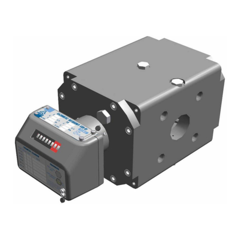
Common CGT-02 Series User manual

TURBINE
GAS METERS
series
CGT-02
OPERATION MANUAL
CGT –OM –18
February 2018
PLEASE READ THE OPERATION MANUAL BEFORE INSTALLING
AND OPERATING THE GAS METER

2
Table of Contents
Page
I. INTENDED USE AND CONDITIONS OF USE 3
II. DESIGN AND FUNCTION 8
III. READOUT DEVICE AND MEASUREMENT OUTPUTS 10
IV. LABELING AND SEALING 18
V. PACKAGING, TRANSPORT AND STORAGE 23
VI. INSTALLATION AND OPERATION 28
VII. OPERATION MONITORING, MAINTENANCE, FAILURES,
REPAIRS 36
VIII. ADDITIONAL EQUIPMENT 37
IX. LIST OF STANDARDS AND TECHNICAL SPECIFICATIONS 42

3
COMMON S.A. CGT-OM-18 february.2018
I. INTENDED USE AND CONDITIONS OF USE
Intended use
CGT-02 turbine gas meters are electromechanical pressure devices designed to measure
the volume of gas flowing through a system. In standard versions, the gas meters may be used
at sites with probable occurrence of explosive atmospheres formed as mixtures of gases
and air classified as explosion groups IIA and IIB. There are also special versions of meters
for group IIC.
Table 1 lists the physical properties of the most common gases and gas mixtures that may be
measured with CGT-02 gas meters. The gas meters are produced with the following
connection types: PN10, PN16, PN20 (ANSI150), PN25, PN40, PN50 (ANSI300),
PN63/PN64, PN100, PN110 (ANSI600).
The turbine gas meters can be used both indoors in stabilized temperature conditions
and outdoors (open locations), however, in the latter case, it is recommended that the gas
meter is shielded from direct exposure to atmospheric factors (metal containers, casings,
roofs, shields etc.)
Conditions of use
1. Directive 2014/32/UE (MID) compliance:
-Certificate PL-MI002-1450CM0003, revision 6
-CE marking 1450, Oil and Gas Institute
-working pressure range p 11 MPa
-ambient temperature range –25°C t+70°C
-gas temperature range –25°C t +70°C
-storage temperature range –30°C t+70°C
-mechanical environment class M2
-electromagnetic environment class E2
-metrological parameters Table 2.
-metrological accuracy class 1.0
-operational position H, HV, VU, VD (for p 0.4 MPa)
-operational position H (for 0.4 MPa < p 11 MPa)
-installation conditions inlet straight pipe with a length of 2 DN
2. IECEx Certyficate of Conformity.
-certificate IECEx KDB 15.0003
-marking standard version Ex ia IIB T5 Gb
special purpose version Ex ia IIC T5 Gb
-ambient temperature –25° C Ta + 70° C
3. Directive 2014/34/UE (ATEX) compliance:
-certificate KDB 04ATEX036, annex 1, 2, 3 and 4
-CE marking 1453, Central Mining Institute, Experimental Mine ”Barbara”
- operation conditions : standard version II 2G Ex ia IIB T5 Gb
special purpose version II 2G Ex ia IIC T5 Gb
- meter case index of protection IP66/IP67
-ambient temperature range –25°C Ta +70°C
Mxx

4
4. Directive 97/23/WE or 2014/68/UE (PED) compliance:
-certificate 10196/JN/2007/C6/001/04 or 59363/JN/001/04
-CE marking 1433, Office of Technical Inspection
-Maximum calculated pressure for gas meter bodies:
connection PN10 PS = 1.0 MPa
connection PN16 PS = 1.6 MPa
connection PN20 PS = 2 MPa
connection PN25 PS = 2.5 MPa
connection PN40 PS = 4 MPa
connection PN50 PS = 5 MPa
connection PN63 PS = 6.3 MPa
connection PN100 PS = 10 MPa
connection PN110 PS = 11 MPa
-ambient temperature range –25°C TS +70°C
5. Directive 2014/30/UE (EMC) compliance:
Requirements met by the use of LF and HF pulse emitters (NAMUR) compliant
with the following harmonized standards: EN 60947-5-2:2007, EN 60947-5-6:2000).
Table 1. Physical properties of the most common gases and gas mixtures that may be
measured with CGT-02 gas meters. Densities are specified under pressure
of 101.325 kPa at 20oC
Gas
or
gas mixture
Chemical
symbol
(formula)
Density
[kg/m3]
Density
relative
to air
Gas meter
version
argon
Ar
1.66
1.38
standard IIB
nitrogen
N2
1.16
0.97
standard IIB
butane
C4H10
2.53
2.1
standard IIB
carbon dioxide
CO2
1.84
1.53
standard IIB
ethane
C2H6
1.27
1.06
standard IIB
ethylene
C2H4
1.17
0.98
standard IIB
natural gas
CH4
ca. 0.75
ca. 0.63
standard IIB
helium
He
0.17
0.14
standard IIB
methane
CH4
0.67
0.55
standard IIB
propane
C3H8
1.87
1.56
standard IIB
carbon monoxide
CO
1.16
0.97
standard IIB
acetylene
C2H2
1.09
0.91
special IIC
hydrogen
H2
0.084
0.07
special IIC
air
–
1.20
1
standard IIB
The basic metrological parameters of CGT-02 turbine gas meters are listed in Table 2.
The table should not be taken as current sales offer; relevant information may be obtained
at the Marketing Department.

5
COMMON S.A. CGT-OM-18 february.2018
The gas meter causes a gas pressure drop in the system. The value of the pressure drop of
CGT-02 gas meters at Qmax maximum flow (specified for air at atmospheric conditions,
i.e. at density 0= 1,2 kg/m3) is specified in Table 2.
In actual conditions, pressure loss pr[Pa] is calculated from the formula:
where: w = / 0 –relative gas density (related to air) according to Table 1,
pa–atmospheric pressure (pa101 [kPa] ),
p –gauge pressure at meter’s inlet [kPa],
Wpd –pressure drop coefficient according to Figure 1.
p –pressure drop at Qmax according to Table 2 [Pa].
·Wpd·p
p
p
p
p
r
a
a
w

6
Fig. 1. Wpd pressure drop coefficient as a function of relative flux Q/Qmax
P [Pa]
Q [m3/h]

7
COMMON S.A. CGT-OM-18 february.2018
Table 2. Basic metrological parameters of CGT-02 meters
DN
nominal
diameter
G
gas
meter
size
Qmax
maximum
flow
Qmin
minimum flow at rangeability:
LF
emitter
constant
HF1, HF2
emitter
constant
(approximate)
HF3 ÷ HF6
emitter
constant
(approximate)
∆p(3)
for
Qmax
1:20(1)
1:20
1:30
1:50(2)
-
-
m3/h
[m3/h]
[m3/h]
[m3/h]
[m3/h]
[pulses /
m3]
[pulses / m3]
[pulses / m3]
[Pa]
DN 50
G 65
100
5
5
-
-
10
2610
94829
760
DN 80
G 100
G 160
G 250
160
250
400
8
13
20
8
13
20
-
8
13
-
-
8
1
1
1
742
742
470
26974
26974
17059
260
620
1500
DN 100
G 160
G 250
G 400
250
400
650
13
20
32
13
20
32
8
13
20
-
8
13
1
1
1
692
692
401
16782
16782
9719
260
670
1580
DN 150
G 400
G 650
650
1000
32
50
32
50
20
32
13
20
1
1
227
227
6873
6873
280
720
G1000
1600
80
80
50
32
0,1
129
3910
1600
DN 200
G 650
1000
-
50
32
20
1
114
3113
260
G 1000
G 1600
1600
2500
-
-
80
130
50
80
32
50
0,1
0,1
116
67
3167
2025
760
1700
DN 250
G 1000
G 1600
G 2500
1600
2500
4000
-
-
-
80
130
200
50
80
130
32
50
80
0,1
0,1
0,1
58
58
34
2111
2111
1223
310
760
1550
DN 300
G 1600
G 2500
G 4000
2500
4000
6500
-
-
-
130
200
320
80
130
200
50
80
130
0,1
0.1
0,1
32
32
19
1181
1181
680
260
650
1600
DN 400
G 2500
G 4000
G 6500
4000
6500
10000
-
-
-
200
320
500
130
200
320
80
130
200
0,1
0,1
0,1
13
13
7,0
444
444
285
170
440
900
(1) –refers to gas meters operating in HV positions, equipped with sealed bearings or a check
valve dedicated for periodic lubricant application (without piston pump and oil
container)
(2) –refers to gas meters for working pressures (p) 2 ÷11 MPa.
(3) –for particular gas meters the measured pressure drop value can be different by ± 5 %
from values specified in Table2.
NOTE: For gas meters equipped with all options (2 HF sensors on the turbine wheel & 2 HF
sensors on the reference wheel & 2 thermowells) the ∆p pressure drop can be
increased by 20%.

8
II. DESIGN AND FUNCTION
Operation of the turbine gas meter is based on the principle of proportionality of the speed
of rotation of a turbine rotor to the linear velocity or the volumetric flow of gas. The gas
flowing into the gas meter (fig. 2) is directed via an inlet straightener into the measurement
assembly and triggers the rotation of the rotor. The rotational motion of rotor is transmitted
to the counter by means of cog gears and magnetic coupling. The counter mechanism totals
up the volume flowing through the device, and an 8-digit counter indicates the total volume.
Each gas meter of the CGT-02 series is verified in the range of Qmin to Qmax (Table 2),
and in that range the accuracy of the meter is verified.
Fig. 2 Cross-section of the turbine gas meter CGT-02

9
COMMON S.A. CGT-OM-18 february.2018
The turbine gas meter CGT-02 (Fig. 2) is built of the following units:
Main body. The main body carries all loads coming from both the gas pressure
and the installation stresses in the pipeline. Bodies of the gas meters with nominal diameters
of DN50 up to DN200 and PN16 or PN20 pressure flange ratings may be manufactured
in two versions –either machined steel forgings or ductile iron castings. Bodies of PN25,
PN40, PN50, PN63, PN100 and PN110 ratings are available only as steel versions. Bodies of
nominal diameters DN250 and larger are always made of welded steel. Each body
is equipped with two connection flanges with type “B” faces and connection dimensions
compliant with the EN 1092-1:2007+A1:2013 and the ISO 7005-1:1992 standards. The
flange dimensions, as well as overall dimensions and estimated weights of the gas meters in
standard versions are listed in Tables 3a and 3b and indicated in Figure 18. On special orders,
the body may be delivered with different types of flange facings compliant with European ,
ANSI or GOST standards. Gas meters bodies are fitted with connectors for high frequency
signal emitters, sockets for pressure gauges and sockets for thermowells (see section III).
Measurement turbine assembly. The measurement turbine assembly consists of the turbine,
the gear system and the inlet straightener. The turbine rotor is placed along the gas meter body
axis and seated on two high precision ball bearings. The flow straightener placed in front
of the turbine makes the gas flow symmetrical and directs it onto the turbine blades. The gear
system (consisting of a worm gear and a spur gears) reduces and transfers the rotational speed
and transmits the drive onto the magnetic coupling.
Drive transmission assembly. The drive transmission assembly consists of a magnetic
coupling with gas-tight partition. The driving part of the coupling is located inside
the partitioned chamber, while the driven part is located outside the partitioned chamber.
The coupling transmits the drive from the pressure zone to the counter assembly, located
outside the gas flow area. The driven part of the coupling may be equipped with a reference
wheel acting as an inducer for the high frequency emitter.
The index assembly. The index assembly reduces the rotational speed further (by means
of a worm gear and spur gears) to drive the mechanical counter and the parts that induce
the low frequency electric signal emitters. The assembly is also fitted with sockets (electrical
outputs) for transmitting the low and high frequency electric signals outside the gas meter.
The gas meter counter can be optionally equipped with a mechanical output. Optionally the
CWSL Encoder can be connected to the optional mechanical output. There are 3 versions of
(optional) Encoders available: CWSL-N, CWSL-A, CWSL-M. Data sent from CWSL-N are
equal to data on the index.
Lubrication system. The lubrication system is used to lubricate the turbine rotor bearings.
The other mechanisms of CGT-02 gas meters are not subject to external lubrication
and make use of bearings equipped with grease reserves. The greasing of the rotor bearings
may be executed by means of a manual piston pump with integrated oil container or via
a lubrication kit.
The CGT-02 series gas meters are offered in the following versions:
maintenance-free (without external lubrication, with spare quantity of grease in bearings);
with special valve for periodic external lubrication (with a lubrication kit);
with piston pump for external lubrication.
The CGT-02 series gas meters can be equipped with piston pumps of the following four
types:
P1 –with pushbutton, pmax ≤ 2 [MPa], DN50, DN80, DN100, DN150,
D1 –with lever, 2 [ MPa] < pmax ≤ 11 [MPa], DN50, DN80, DN100, DN150,

10
D2 –with lever, pmax ≤ 6.3 [MPa], DN200, DN250, DN300, DN400,
D3 –with lever, 6.3 [ MPa] < pmax ≤ 11 [MPa], DN200, DN250, DN300, DN400.
Typical DN50 gas meters are not adapted for external lubrication. These meters can be
optionally equipped with piston pump or lubrication valve.
A sticker is attached to the oil container cover, providing information about the type
of the pump used and the type of oil which should be used. Information about the type of oil
is also provided on the lubrication valve cover.
III. READOUT DEVICE AND MEASUREMENT OUTPUTS
The gas meter CGT-02 is equipped with a readout device in the form of a mechanical
counter with electric signal outputs. The body of the gas meter is equipped with sockets
for implementation of external HF emitters and sockets for the (optional) measurement
of pressure and temperature. Such measurements enable monitoring the gas meter operation
and connecting to the external equipment. Fig. 3 shows the location of the measurement
outputs of the gas meter.
The mechanical counter is located inside the index head assembly and visible through
a polycarbonate inspection window. The counter allows direct readout of the actual volume
of gas that has flown through the gas meter under particular pressure and temperature
conditions. The index assembly may be rotated around its axis in a range of ca. 350o, allowing
for convenient readout of the counter from virtually all directions.
Fig. 3. Location of measurement outputs of CGT-02 gas meters.

11
COMMON S.A. CGT-OM-18 february.2018
Mechanical counter output. The gas meter may be optionally equipped with a mechanical
output. A flattened tip of the counter shaft is located on the left side of the index head
and covered by a protective cap. The mechanical output may be used to drive external
devices. The rotational speed of the shaft is identical to the speed of the fastest counter drum.
The shaft rotates counter clockwise which is marked on the name plate located on the housing
of mechanical output (Fig. 11). There are also 2 other values specified on this name plate:
Mmax = 0,25 [Nmm] maximum permissible torque load on the shaft of the mechanical output,
and 1 tr = …… [m3] value of the constant corresponding to one rotation of the shaft.
Fig. 4. Mechanical output dimensions
Electrical counter outputs. There are two possible types of electric signal outputs:
low frequency (LF) outputs and high frequency (HF) outputs. The index head can be equipped
with one or two 6-pins sockets. Up to three electric pulse emitters can be connected to each
of the sockets. The pulse emitters are:
-one or two inductive high frequency emitters HF,
-one or two inductive low frequency emitters LFI,
-one or two low frequency reed contact emitters LFK,
-one or two low frequency emitters LFW equipped with Wiegand sensor
-one control circuit utilising normally closed reed relay switch AFK.
The reed relay emitters LFK and LFW are designed to work with a battery-powered
or grid/battery-powered data logger and volume converter located in the vicinity of the gas
meter (up to ca. 2 m). The induction emitters, both of the LFI and the HF type, may emit
electric current signals over significantly longer distances (up to ca. 200 m, depending
on conditions). Due to high power consumption, they are designed to work only with grid-
powered volume converters. Gas volumes corresponding to individual pulses of the LF
emitter are presented in Table 2.
The number of HF pulses per one cubic meter of gas is determined individually for each gas
meter and listed on the type plate.
All emitters located in the gas meter index head are connected to Tuchel C091 31N006 100 2
or Lumberg Connect 0304 06 sockets located in the back wall of the index. Cords connected
to sockets should be equipped with Tuchel C091 31H006 100 2 or Lumberg 0332 06 plugs.
Tuchel connections in CGT-02 gas meters are of the IP67 protection class. Table 3 presents
possible connections of emitters to individual electric signal output sockets.

12
Table 3. Possible connections of gas meter emitters to index output sockets
Pin
Polarity
LFK 1
or
LFW 1
LFK 2
or
LFW 2
AFK
(*)
LFI 1
(*)
LFI 2
HF 1
HF 2
Socket 1
1
S
O
4
+
S
O
2
O
P
P
O
O
5
+
O
P
P
O
O
3
O
P
6
+
O
P
Socket 2
1
P
O
4
+
P
O
2
O
O
O
P
O
5
+
O
O
O
P
O
3
O
P
6
+
O
P
S –standard connections, P –preferred connections, O –optional connections
(*) –not available with replacaeable LF sensors
The view and numbering of the pins Sockets 1 and 2 is shown in Figure 9a (9b).
Standard versions of the CGT-02 gas meter features only one
low frequency reed contact emitter LFK 1
ATTENTION!
In the case where two sockets in the index head are used as an output for the sensor's circuits, the
cables connected to those sockets should be marked with tags indicating the socket number to which
the specified cable should be connected.
One of the inductive emitters HF3 to HF6 installed in the gas meter body may act as a control
element in the CGT-02 meter. The constants for emitters HF3-HF6 are listed on the type
plate.
In line with the conditions of use, the CGT-02 gas meters should be equipped with emitters
allowing for at least II 2G Ex ib IIC T5 Gb protection. This condition is satisfied
for instance by the following emitters used in the index:
-HF type Bi1-EG05-Y1(1) by Hans Turck GmbH
Certificate No. IECEx KEM 06.0036X marking Ex ia IIC T4... T6
Certificate No. KEMA 02ATEX1090X marking II 1G Ex ia IIC T4...T6 or
II 2G Ex ia IIC T4...T6
-LFI type Si5-K09-Y1(1) by Hans Turck GmbH
Certificate No. IECEx KEM 06.0036X marking Ex ia IIC T4... T6
Certificate No. KEMA 02ATEX1090X marking II 1G Ex ia IIC T4...T6 or
II 2G Ex ia IIC T4...T6
-LFK type CLFK-03 by Common S.A.
-LFW type CLFW-01 by Common S.A.
-LFW type CLFW-02 by Common S.A.
(1) –required linear characteristics of the emitter power circuit.

13
COMMON S.A. CGT-OM-18 february.2018
Acceptable intrinsic safety parameters
Bi1-EG05-Y1
Si5-K09-Y1
CLFK-03
CLFW-01
CLFW-02
Ui= 20 V DC
Ui= 20 V DC
Ui= 15.5 V DC
Ui= 30 V DC
Ii= 60 mA
Ii= 60 mA
Ii= 52 mA
Ii= 52 mA
Pi= 200 mW
Pi= 130 mW
Pi = 169 mW
Pi = 0.6 W
Li= 150 μH
Li= 350 μH
Li≈ 0
Li≈ 0
Ci= 150 nF
Ci= 250 nF
Ci≈ 0
Ci≈ 0
ATTENTION!
The total voltage of separate galvanic intrinsically safe circuits connected
to one connector must comply with: Ui1 + Ui2 ≤ 30 V
Intrinsic safety parameters of the emitters installed in the gas meter are listed
on the type plate.
The security level is also met by the following interchangeable transmitters:
-LFK type CLFK-04 manufactured by Common S.A.
-LFW type CLFW-04 manufactured by Common S.A.
Acceptable intrinsic safety parameters
Electrical outputs for HF emitter signals in the gas meter body.
The high frequency pulse emitters may be placed in the main body of the gas meter
over the turbine rotor or over the reference wheel (option), which features the number of cogs
equal to the number of turbine blades. In such case, the magnetic field of the HF emitter
is modulated by the turbine rotor or the reference wheel giving the same pulse rate.
The HF emitters can be installed as shown in Fig. 3. The sockets feature a M16 x 1.5 thread
(Fig. 5).
Installation of the HF emitter in the gas meter body requires high precision and the use
of electronic control equipment and such must be performed only by a representative
of the manufacturer or a company authorized by the manufacturer.
Maximum of four near field inductive high frequency emitters (HF) may be installed
in the gas meter:
-one or two HF emitters over the turbine rotor,
-one or two HF emitters over the optional reference wheel.
CLFK-04
CLFW-04
Ui= 15.5 V DC
Ui= 30 V DC
Ii= 52 mA
Ii= 52 mA
Pi = 169 mW
Pi = 0.6 W
Li≈ 0
Li≈ 0
Ci≈ 0
Ci≈ 0

14
The emitters should allow for at least 2G Ex ib IIC T5 Gb protection. These conditions
are satisfied, for example, by the following emitters:
-CHFI-01 by Common S.A., equipped with Bi1-EG05-Y1(1) sensors (Hans Turck
GmbH: Certificate No.: IECEx KEM 06.0036X, marking Ex ia IIC T4...T6 and
Certificate No.: KEMA 02ATEX1090X marking II 1G Ex ia IIC T4...T6 or
II 2G Ex ia IIC T4...T6)
-CHFI-03 by Common S.A., equipped with Bi3-EG12-RY1/S1000(1) sensors
(Hans Turck GmbH, Certificate No.: KEMA 02ATEX1152X
marking II 1G Ex ia IIC T4...T6 or II 2G Ex ia IIC T4...T6)
(1) –required linear characteristics of the emitter power circuit.
Fig. 5. Dimensions of the sockets for the HF pulse emitters.
Acceptable intrinsic safety parameters:
CHFI-01
CHFI-03
Ui= 20 V DC
Ui= 20 V DC
Ii= 60 mA
Ii= 60 mA
Pi= 200 mW
Pi= 200 mW
Li= 150 μH
Li= 350 μH
Ci= 150 nF
Ci= 180 nF
Intrinsic safety parameters are listed in the type plate located at the emitter casing
(Fig. 10).
The emitters are equipped with 4-pin Tuchel C091 31W004 100 2 connectors. They should be
connected to cords with Tuchel C091 31D004 100 2 slots. The emitter is connected to pins
3 and 4. Figure 6 presents a diagram of the connection of the emitter to the measurement
circuit.

15
COMMON S.A. CGT-OM-18 february.2018
Fig. 6. Diagram of the HF emitter connection
The number of HF pulses per one square meter of gas is determined individually for each
gas meter and listed on the electrical outlets type plate. (Figs. 9 and 10), placed at the top
of the index head.
NOTE!
Intrinsic safety parameters are electrical parameters designated during analysis of
construction of intrinsically safe device. Their values are determined for the most unfavorable
state of work or damage to the device. The values of these parameters are limited to the levels
that are safe for the given explosive mixture. They should not be treated as technical
parameters of the device's operation.
The conditions for compliance of the intrinsic safety parameters of connected devices
are presented in the table below.
Conformity conditions for intrinsic safety parameters
Connected external device
Condition
Gas meter
Output voltage
Uo
Ui
Input voltage
Output current
Io
Ii
Input current
Output power
Po
Pi
Input power
Maximum external capacity
Co
Co Ci+Ck
Ci
Internal capacity
Maximum external inductance
Lo
Lo Li+Lk
Li
Internal inductance
The distributed parameters of cables (Ck), (Lk) should be taken as:
The least favorable parameters given by the cable manufacturer or
Parameters measured in accordance to EN 60079-14 or 200pF/m & 1H/m or
30H/where the connection consists of 2 or 3 wires (with or without shield)
Rated operating parameters of used transmitters:
LFK transmitters –reed contact and LFW with output type „open collector”
CLFK-03 / CLFK-04 / CLFW-01 / CLFW-02 / CLFW-04
Closed contact resistance Rz= 100÷ 2 k,
Open contact resistance Ro> 100 M,

16
Maximum switching frequency fp= 2 Hz .
Inductive slot transmitters and inductive proximity transmitters in NAMUR standard.
Si5-K09-Y1 Bi1-EG05-Y1
CHFI-01, CHFI-03
Maximum switching frequency fp= 2 Hz, fp= 0,5 kHz.
Rated operating voltage Un = 8,2V
Rated current of the non-activated sensor I >= 2,1mA
Rated current of the energized sensor I <= 1,2mA
Other rated operating parameters of the transmitters are in accordance with the
requirements of PN-EN 60947-5-6: 2002.
When connecting transmitters to inputs of pulse receiving devices, the polarity of conductors
should be maintained. Only LFK and AFK transmitters do not require polarization.
The HF outputs are particularly useful for recording fluctuations and rapid changes of the gas
flow.
Pressure measurement outputs.
Pressure measurement outputs are located on both sides of the main body of the meter
(Fig. 3). They are machined as ¼NPT taper threads (Fig. 7).
a.) b.)
Fig. 7. ¼ NPT pressure measurement output
The outputs are adjusted to connecting pressure transducers, either directly to the socket
or through impulse lines and three-way valves (impulse line connector, Fig. 7b). Outputs
that are not in use are closed with plugs (Fig. 7a). Both plugs and sockets may be secured
with installation seals.

17
COMMON S.A. CGT-OM-18 february.2018
Temperature measurement outputs.
CGT-02 turbine gas meters are equipped with temperature measurement outputs only when
delivered as a special order version; temperature sockets are not available in standard
versions.
Temperature measurement outputs are located on both sides of the main body of the meter
(Fig. 3.; in case of DN50 meters versions with one or two sockets are available). Thus one
or two thermowells can be installed. Standard thermowells, with M12x1.5 female thread
sockets (different threads on order), are to be filled with silicone oil and fitted with one of two
types of electric thermometers (Fig. 8a and 8b) or plugged (Fig. 8c). Temperature sockets,
when thermowells are not installed, must be plugged with ¼NPT plugs (like on Fig. 7a).
a) thermometer type 1 b) thermometer type 2 c) thermowell plugged
Fig. 8 Temperature outputs with thermowells

18
IV. LABELING AND SEALING
Information on the basic technical parameters of the gas meter along with the serial
number and manufacture year is listed on type plates (Figs. 9a and 9b) screwed to the index
head. The direction of gas flow is marked on the upper side of the meter body (red arrow)
and there are labels indicating electrical (HF) and mechanical outputs as well as pressure
and temperature measurement outputs on the meter (Fig. 11).
Fig. 9a. Type plates –standard version

19
COMMON S.A. CGT-OM-18 february.2018
Fig. 9b. Type plates –special version example
Fig. 10. HF emitter type plate
Fig. 11. Markings of pressure and temperature measurement outputs, HF outputs, mechanical output,
and example of oil & oil pump type.
After verification by the authorized laboratory, each gas meter is secured
with seals. Locations of the seals are shown in Fig. 12a and 12b. Seal P1 features the original
validation or revalidation stamp (Fig. 13a) while seals P2, P3, P4, P5, P6, P7, P8, P9, P10
feature protection stamps (Fig. 13b).
By request of the customer, the gas meter may be delivered along with the certificate
that documents its verification/calibration.

20
The original verification stamp seal is required for the gas meter to be considered
a legal measurement device.
Installation seals placed at the connectors of the pressure transducers (P7), HF emitters (P8),
temperature transducers (P9) and possibly at the mechanical output (P10), may feature stamps
placed by the manufacturer, gas supplier or authorized installer. In addition, installation seals
should be placed on the blinders (plugs) of unused electrical outputs and possibly
on the three-way valve connected to the volume converter (see section VIII.)
The original verification period depends on metrological regulations in the country
of installation. Before the expiration of the verification period, the gas meter should be
submitted for secondary verification in an authorized laboratory (viable turnaround time
for the verification procedure in a laboratory should be taken into account).
Fig. 12a. Locations of seals on CGT-02 gas meter (version 1)
Table of contents
Other Common Measuring Instrument manuals
Popular Measuring Instrument manuals by other brands

Conrad Electronic
Conrad Electronic 2884220 operating instructions

Piusi
Piusi K500 user manual

London Electronics
London Electronics Fusion-L 6 digit Connection details, scaling and general information

Thermometer
Thermometer 8000 operating instructions

SMC Networks
SMC Networks PPA100 Series instruction manual

Simex
Simex STI-638 user manual