COMMON S.A. OPERATING INSTRUCTION CMK-03
9
The CZAK-03 Communication and Signal Barrier
The detailed information are contained in the manual instruction and
the technical documentation of this device —available on the web
site www.common.pl
Optical communications interface COGUSB-03.
Detailed information contains manual instruction and technical doc-
umentation of the device available on web site: www.common.pl
The female, TUCHEL contact, C091D Type (to the COM1 trans-
mission port)
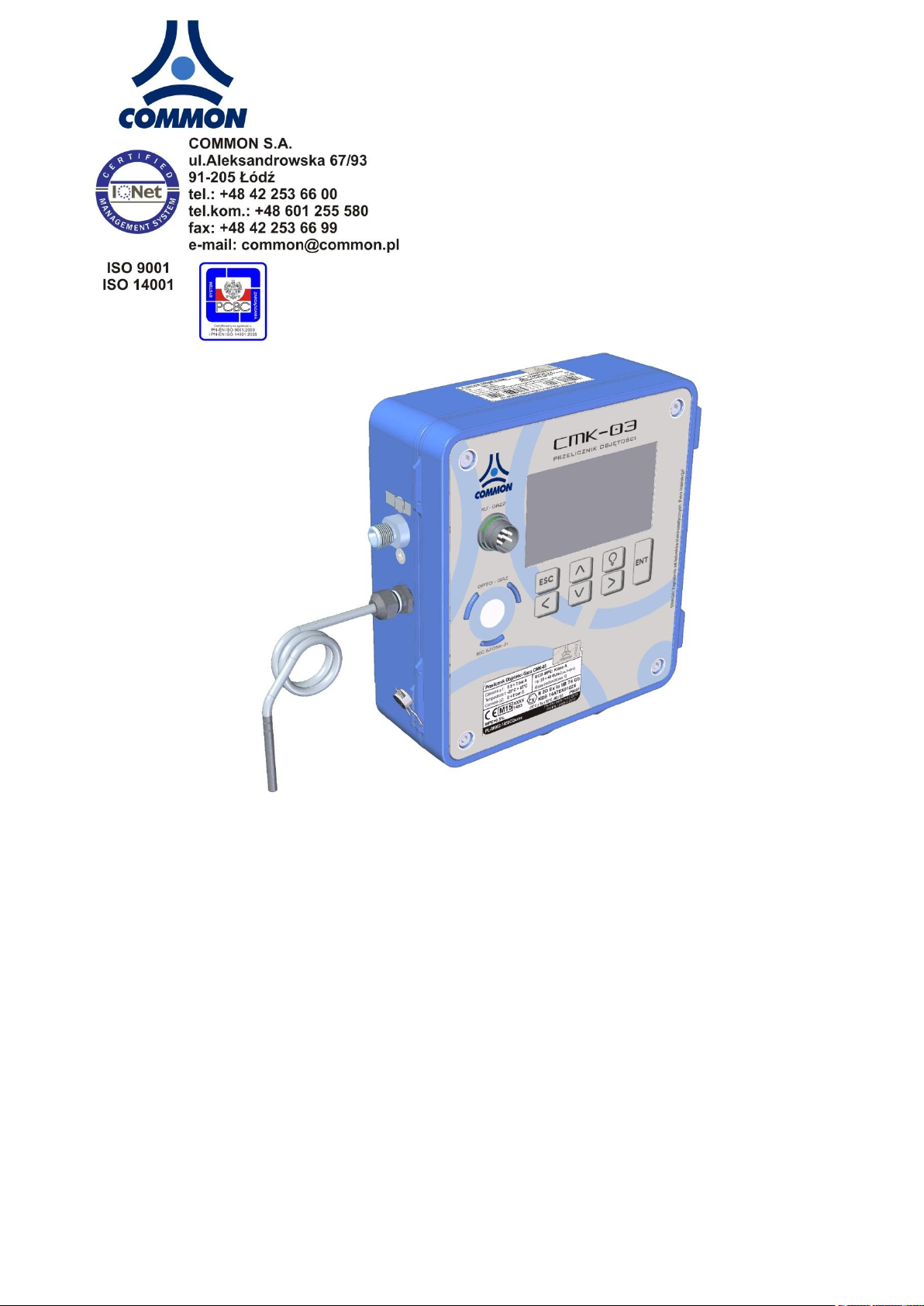
3. CONSTRUCTION
The CMK-03 Gas Volume Converter is a measuring and accounting instrument which fulfills the requirements of
MID Directive. The device is dedicated to operate on the measuring and reducing & measuring gas stations. It
can be used with any of the gas meter (turbine, rotor or ultrasonic) which provides information about measured
volume in the pulses.
The CMK-03 is a battery power supplied instrument with possibility to operate on the external power supply. The
installed batteries provide continuous and service less data registration for a minimum 6 years.
The CMK-03 is a volume converter of the gas Type 1. This is complete measurement system, equipped in the
pressure converters, the temperature converters, the input of pulses/volume of the meter and the algorithms for
converting the measured volume of gas to the basic conditions.
The construction of the CMK-03 has an additional inputs and outputs, which allow for a usage to the technological
purpose and to the control and measurement processes. The inputs and outputs are listed below:
control inputs LFb and LFc
Encoder input,
HF transmitter input in NAMUR standard
double ExtCPC input for external technological CPC-03 converters,
double-state, signal outputs OUT
double-state, signal inputs IN
input IN in NAMUR standard
The data reading and also the CMK-03 power supply are carried out by using three independent communication
ports in the RS-GAZ2 standard: COM1 ("Tuchel/OPTO-gas"), and COM2 and COM3.
The housing is made from the aluminum what assure durability, resistance and a high level of waterproofness —
IP66/67. The opening of the cover is a hinge with the limiter what allows for easy access to the wire clamps and
the battery unit.
The LCD display with keyboard, the port OPTO-GAZ port and the RS-GAZ2 (TUCHEL) port are located in the
device cover. There are maximum two pressure converters P1 and P2 which are built in the housing base.
The P1 Converter occurs also as an external version which is constant connected via a cable with the CMK-03.
The metal cable glands are located in the base of the housing. They are adapted for the shielded cables. This
solution raises the resistance of the device electrical circuits against the electromagnetic interference.