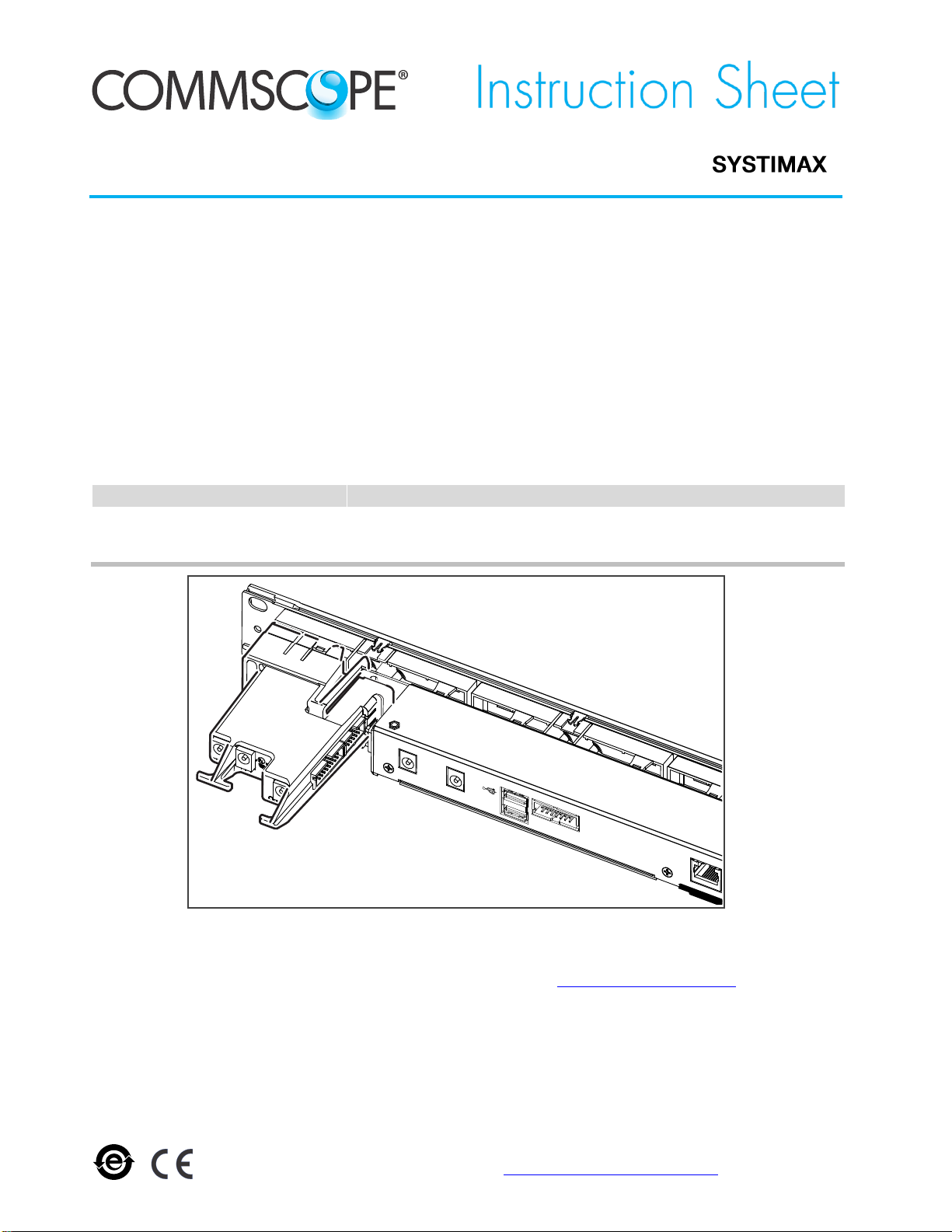
CommScope SYSTIMAX imVision imPower User manual

860610260
Issue 2, April 2016
www.commscope.com
®
SYSTIMAX®imVision®imPower™Power Extender
Installation
© 2016 CommScope, Inc.
All rights reserved
This product is covered by one or more U.S.
patents or their foreign equivalents. For patents, see
www.commscope.com/ProductPatent/ProductPatent.aspx
Page 1 of 5
For RoHS Inquiries:
CommScope Inc.
Corke Abbey, Bray
Co. Dublin, Ireland
Attn: Legal Department
General
The SYSTIMAX®imVision®imPower™ power extender can accommodate additional 96-fiber LC or MPO
modules to communicate with an imVision®controller. The imVision imPower supports redundant power for
iPatch®panels, with the ability to feed additional power to the imVision controller. A ribbonized cable is used
to connect the imPower to the panel bus to enable twice as many 96-fiber LC or MPO modules to
communicate with the imVision controller.
Ordering Information is listed below:
Material ID
Part No.
Description
760219345
imV-imP
imVision imPower power extender
760224832
imV-imP-AR
imVision imPower power extender (Argentina version)
imPower™Power Extender with imVision®Controller
How to Contact Us
To find out more about CommScope® products, visit us on the web at http://www.commscope.com/
For technical assistance:
- Within the United States, contact your local account representative or technical support at 1-800-344-0223.
Outside the United States, contact your local account representative or PartnerPRO™Network Partner.
- Within the United States, report any missing/damaged parts or any other issues to CommScope Customer Claims
at 1-866-539-2795 or email to claims@commscope.com. Outside the United States, contact your local account
representative or PartnerPRO Network Partner.
PANELBUS
Display
PWR2
PWR1
OUT
B

860610260
Instruction Sheet
www.commscope.com
Page 2 of 5
Parts List
Verify parts against the parts list below:
Quantity
Description
1
imPower assembly
1
Power jumper cable
1
48” (1.2m) ribbonized flat jumper cable, 16 pin
1
7” (0.2m) ribbonized flat jumper cable, 10 pin
1
AC to DC power supply 12V, 2.08A (imV-imP kit only)
1
Installation instruction sheet
Separately Orderable Items
A backup (redundant) power supply is available for the controller. Ordering information is listed below:
Material ID
Part No.
Description
760219501
imV-imP-JMP
Power extender cable package
760222448
im-POWER-SUPPLY
Power supply, backup
CommScope approved power supplies may be obtained from the vendor, Globtek, Inc:
model # GT-41060-2512, part no. WR9QE2080LR9P-NK7REB
Refer to the Power Supply Specifications for imVision Products (860625094).
Specifications
Power: 12 VDC at 25 W (imVision Controller+Panels)
Programming:
Downloadable software
Program data retention without power:
Minimum 10 years
Connections:
Up to 45 1U 24-port copper panels or fiber shelves
Up to 52 rows of 96-fiber LC or MPO modules
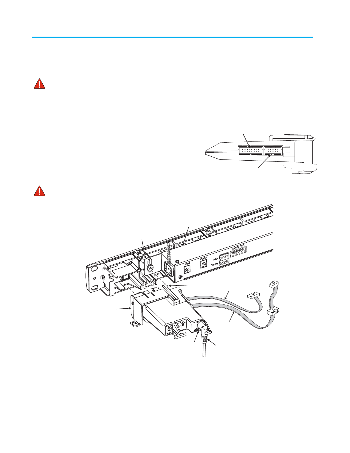
Recommended Mounting:
Back of the imVision controller on the left side
Operational Environment:
Temperature range: 32°F to 122°F (0°C to 50°C)
CAUTION Read and understand all instructions.
When installing, operating, or maintaining SYSTIMAX equipment, basic safety precautions should always be followed to
reduce the risk of fire, electric shock, and injury to persons, including the following:
This product should be operated using only the power supply provided by CommScope with the product. Consideration
should be given to the connection of the equipment to the supply circuit and the effect that overloading of the circuits
might have on over current protection and supply wiring. Appropriate consideration of equipment nameplate ratings
should be used when addressing this concern.
Never install this product in wet locations or during lightning storms. There is a remote risk of electric shock.
When installing SYSTIMAX equipment not described in this guide, follow the instructions provided with that equipment.
Care should be taken not to compromise the stability of the rack by installation of equipment.
To reduce the risk of an electrical shock, do not disassemble this product. Service should be performed by trained
personnel only. Opening or removing covers and/or circuit boards may expose you to dangerous voltages or other risks.
Incorrect reassembly can cause electrical shock when the unit is subsequently used.

www.commscope.com
860610260
Instruction Sheet
Page 3 of 5
Installation of the equipment in a rack should be such that the amount of airflow required for safe operation of the
equipment is not compromised.
To be installed in restricted access areas only.
Note: All wiring that connects to the imVision or imPower equipment must meet applicable local and national building
codes and network wiring standards for communication cable.
Important: Limits for iPatch panel connections to panel bus
Limit the chain of iPatch panels connected to each cable bus port to a maximum of five connectors (including controller).
Start a new chain of panels with every sixth panel in the rack system.
Step 1 –Connect Ribbonized Jumper Cables to imPower
1. Plug both ribbonized jumper cables, provided, into the
imPower unit in the proper connectors as shown.
2. Connect included power jumper cable to the OUT power
jack on the imPower.
Note: Hold power connector at a 90° angle to the imPower,
push to seat connector, then turn the connector so the cable
is oriented in the down position. Ensure that the cable is
secured behind extended tab at back of housing as shown in
Step 4.
Important: Power should be removed from the imVision
controller prior to installing or removing panel bus jumper cables.
Step 2 –Install imPower
1. Ensure that the space in back on the left side of the imVision controller is clear from obstruction and can
accept installation of the imPower as shown.
2. Maneuver the extensions on front of imPower into the openings on the left side of imVision controller and
push power extender into place. Make sure imPower is aligned correctly.
3. Ensure that the latch secures the imPower to the imVision’s 1U space. Hook latch behind controller flange.
Squeeze latch with thumb to release latch when removing imPower.
Latch hooks behind
controller flange
imVision
controller
imPower
16-pin
jumper cable
10-pin jumper
cable
Latch
Power jumper cablePower OUT
imPower Side View
16-pin ribbonized
cable connector
10-pin ribbonized
cable connector

860610260
Instruction Sheet
www.commscope.com
Page 4 of 5
Alternate Mounting Method
4. An alternate method for mounting involves sliding the imPower onto the farthest left cable management bar
for the imVision controller as shown.
Step 3 –Connect Ribbonized Jumper Cables to Controller and Panel Bus
Note: imPower connections will replace existing data and power connections for installed imVision controllers.
Disconnect female 10-pin connector from panel bus, removing jumper.
1. Ribbonized jumper cables transmit data communication through the controller and panel bus.
The 10-pin jumper cable terminates at the imVision controller 14-pin panel bus port.
The 16-pin panel bus jumper cable female 10-pin connector plugs into the panel bus port closest to
center of panel bus, as shown below. Loose jumper cable can be inserted in the two adhesive clips on
bottom of controller. Insert panel bus jumper’s additional 10-pin male connector onto panel bus strip for
additional capacity.
Note:For proper system function, it is imperative that the panel bus jumper cable is plugged at the middle of the
panel bus. Other locations (higher or lower on panel bus) could result in unreliable communications between the
imVision controller and the iPatch panels that are installed on the panel bus.
PWR 2 PWR 1 PanelBus
PWR
2PWR 1
OUT
Outlet
imVisioncontroller
imPower
14-pin port
10-pin
female
connector
16-pin long
jumper cable
10-pin short
jumper cable
PWR1
Power jumper cable
Out
10-pin
male connector
Panel bus
Slot on used
for alternate mounting
imPower
imPower

www.commscope.com
860610260
Instruction Sheet
Page 5 of 5
Step 4 –Connect Power Source to imPower and Controller
Note: imPower connections will replace existing power connections for installed imVision controllers. Remove
installed power cord from the PWR1 port on controller.
1. Plug the other end of the power jumper cable into the imVision controller power input, PWR 1. See diagram
on preceeding page.
2. Connect the provided power supply cord into the P1 power jack on the rear of the imPower and
turn the connector so the cable is oriented in the down position to ensure that the cable is secured.
Note: Hold power connector at a 90° angle to the module,
push to seat connector, then turn the connector so the
cable is oriented in the down position. Ensure that the
cable is secured behind extended tab at back of housing
as shown.
3. Select and install the appropriate power supply adapter
into plug base unit, then plug unit into an approved power
outlet.
Note: A redundant power supply connection (P2) is provided
in case that option is required. Power supply must be ordered
separately.
Step 5 –Power Up Controller
1. Please go to the CommScope eCatalog to download the
SYSTIMAX imVision Controller Installation Guide
(860526839).
2. Power up imPower and imVision controller and configure settings and panels as described in the
installation guide.
OUT
B
imPower
P2P1
Power
OUT
PWR1
Controller
Power jumper cable
Power supply
to power outlet
Optional redundant
power connection
To panel bus
Extended
tab
Rotate cable end
90° after seating
Extended
tab
imPower
This manual suits for next models
4
Table of contents
Other CommScope Extender manuals

CommScope
CommScope ION-U L 7/8/85/17/19 User manual

CommScope
CommScope Sprint AIRAVE 3 LTE User manual

CommScope
CommScope PFU-P-C-O-060-02 User manual

CommScope
CommScope ION-U EU L 17EP/17EP User manual

CommScope
CommScope PFU-P-E-O-060-01 User manual

CommScope
CommScope ION-U EU L 25T/25T User manual

CommScope
CommScope PFU-P-C-O-060-02 User manual