manuals.online logo
Brands
  1. Home
  2. •
  3. Brands
  4. •
  5. CommScope
  6. •
  7. Recording Equipment
  8. •
  9. CommScope FD Panel User manual

CommScope FD Panel User manual

Popular Recording Equipment manuals by other brands

ThermoFisher Scientific Dionex DRS 600 Installation checklist

ThermoFisher Scientific

ThermoFisher Scientific Dionex DRS 600 Installation checklist

Shure ANIUSB-Matrix user guide

Shure

Shure ANIUSB-Matrix user guide

Nady Audio HE-1 user guide

Nady Audio

Nady Audio HE-1 user guide

AUDAC APM 01 User manual & installation guide

AUDAC

AUDAC APM 01 User manual & installation guide

Teac GF-350 owner's manual

Teac

Teac GF-350 owner's manual

Fractal Audio MFC-101 MARK III owner's manual

Fractal Audio

Fractal Audio MFC-101 MARK III owner's manual

bmcm USB-OI16 manual

bmcm

bmcm USB-OI16 manual

HHB BurnIT CDR-830 Service manual

HHB

HHB BurnIT CDR-830 Service manual

GE VersaMax IC200CPUE05 manual

GE

GE VersaMax IC200CPUE05 manual

IntesisBox MH-RC-MBS-1 user manual

IntesisBox

IntesisBox MH-RC-MBS-1 user manual

Attero Tech unD4l user manual

Attero Tech

Attero Tech unD4l user manual

Sennheiser UI 765 instruction manual

Sennheiser

Sennheiser UI 765 instruction manual

Sony RCD-W1 Operating Instructions  (primary... Service manual

Sony

Sony RCD-W1 Operating Instructions (primary... Service manual

Roland Planet-P  MKS-10 owner's manual

Roland

Roland Planet-P MKS-10 owner's manual

Roland BOSS GT-PRO Turbostart

Roland

Roland BOSS GT-PRO Turbostart

8x8 Inc Valcom V-2001A manual

8x8 Inc

8x8 Inc Valcom V-2001A manual

Waves SUB Align user guide

Waves

Waves SUB Align user guide

Mitsubishi Electric MAC-334IF-E installation manual

Mitsubishi Electric

Mitsubishi Electric MAC-334IF-E installation manual

manuals.online logo
manuals.online logoBrands
  • About & Mission
  • Contact us
  • Privacy Policy
  • Terms and Conditions

Copyright 2025 Manuals.Online. All Rights Reserved.

Quick
Start
CommScope (logo) and CommScope are trademarks.
660002346 Rev C © 2018, CommScope, Inc. All Rights Reserved.
26808-A
TC-96248-IP · Rev C · December 2018
FD Panel
Unpack the panel and check for shipment damage.
Report any damage to the carrier and also file a report at
www.commscope.com/SupportCenter
DEFAULT MOUNTING BRACKET POSITION
BACK OBLIQUE VIEW OF DEFAULT MOUNTING BRACKET POSITION
Remove the shipping brackets.
2
1
3
4Mount panel to rack, and secure the
vertical cable guides using screws provided.
Select panel mounting option to be used. Panel is shipped
with mounting brackets in position shown. If desired, brackets
can be removed and re-mounted in alternative position.
ALTERNATIVE MOUNTING BRAC KET POSITION
REMOVE
MOUNTING
SCREWS
(4 Places)
SHIPPING
BRACKET (2X)
CABLE
BRACKET (2X)
These instructions apply to both 1RU and
2RU panels.
NOTE:
5Ground the panel using the
2-hole lug provided.
Adhere to local standards.
Remove brackets one
at a time.
NOTE:
NOTE:
Based on
rack type,
select from
screws
provided.
NOTE:
Secure
cable
bracket to
to the
lowest hole
of the
mountng
bracket.
NOTE:
1-hole lug
is also
provided.
Parts List
DESCRIPTION
FD PANEL
#12-24 X 1/2” SCREWS & LOCK WASHERS
QTY
1
44
M6 - 1 X 12mm SCREWS & LOCK WASHERS4
VERTICAL CABLE GUIDES (VCGs)2
PARTS LIST
ADDITIONAL SHORT VCGs
#12-24 X 3/4” SCREWS
2
2
M6 - 1 X 20mm SCREWS2
VELCRO STRAP (LENGTH 4 FT.)1
2-HOLE LUG, #6 WIRE1
1-HOLE LUG, #14-6 WIRE1
Required Tool PHILLIPS #2 SCREWDRIVER
© 2018, CommScope, Inc. All Rights Reserved.
TC-96248-IP Rev C December 2018
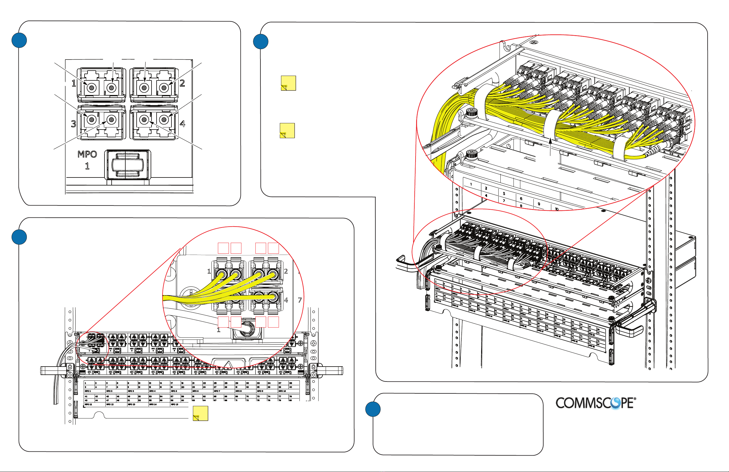
Customer Interface Connections from MPO patch cord
to LC patch cord are as indicated below.
26809-A
7
6
When cabling the other (right) side of the
panel, route cables and patch cords in the
opposite direction, toward the right side.
(Left and right side routing should be mirror
images of one another.)
Continue to the right, connecting
MPO-LC sections while routing the MPO
cable and LC patch cords to the left
as shown. Route the cables and patch cords
up or down the rack to the cable runway.
Beginning at the MPO-LC section 1
on the left side, connect the
first MPO patch cord
then connect the related LC
patch cords
per the picture above.
NOTE:
Order the cables neatly using velcro straps;
cut to length needed.
TECHNICAL ASSISTANCE AND PRODUCT INFORMATION
http://www.commscope.com/SupportCenter
PRODUCT PATENTS
http://www.cs-pat.com
NOTE:
When connecting lower row connectors,
remove thumb screws on cable management
bar to allow bar to move and provide better
access to lower row. Use caution not to
stress cables attached to cable bar.
9
MPO
FIBER 11
MPO
FIBER 1
MPO
FIBER 4
MPO
FIBER 12
MPO
FIBER 3
MPO
FIBER 2
MPO
FIBER 9
MPO
FIBER 10
BABA
ABAB
NOTE: Since the bottom duplex adapters/connectors
are upside down, they are reversed (”AB”
instead of “BA,” as shown in detail above).
8
VELCRO
STRAP