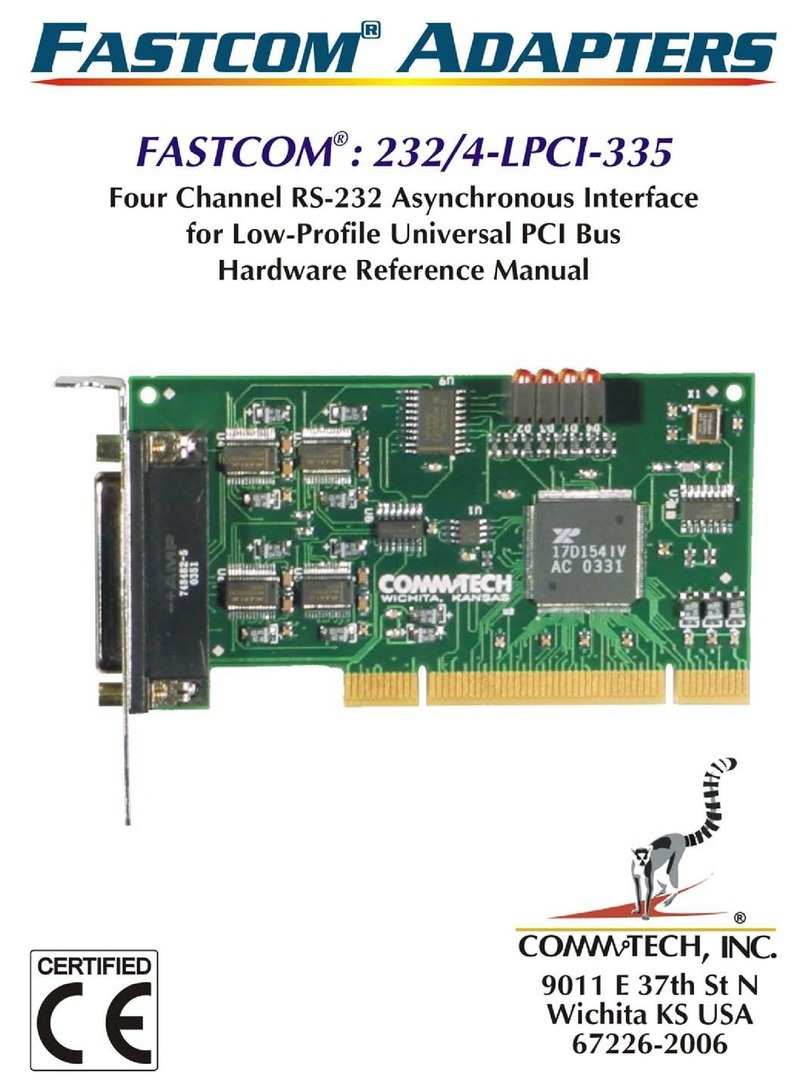
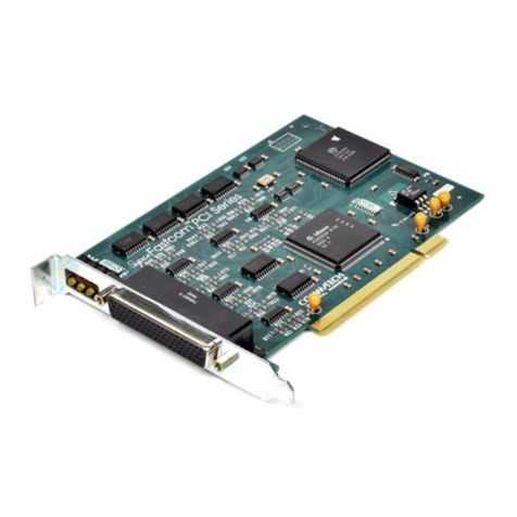
CommTech FASTCOM ESCC-PCI-335 Quick user guide

-~
ARTISAN
®
~I
TECHNOLOGY
GROUP
Your definitive source
for
quality
pre-owned
equipment.
Artisan Technology
Group
Full-service,
independent
repair
center
with
experienced
engineers
and
technicians
on staff.
We
buy
your
excess,
underutilized,
and
idle
equipment
along
with
credit
for
buybacks
and
trade-ins
.
Custom
engineering
so
your
equipment
works
exactly as
you
specify.
•
Critical
and
expedited
services
•
Leasing
/
Rentals/
Demos
• In
stock/
Ready-to-ship
•
!TAR-certified
secure
asset
solutions
Expert
team
ITrust
guarantee
I
100%
satisfaction
All
tr
ademarks,
br
a
nd
names, a
nd
br
a
nd
s a
pp
earing here
in
are
th
e property of
th
e
ir
r
es
pecti
ve
ow
ner
s.
Find the Commtech FastCom ESCC-PCI-335 at our website: Click HERE

F ™ A
ASTCOM DAPTER
S
F
A
S
T
C
OM
™
:
ES
CC
-
P
C
I
-
335
H
i
g
h
S
p
ee
d
D
u
a
l
C
h
a
nn
e
l
S
y
n
c
/
A
s
y
n
c
I
n
t
e
r
f
ace
f
o
r
U
n
i
ve
r
s
a
l
P
C
I
B
u
s
H
a
r
d
w
a
r
e
R
e
f
e
r
e
n
ce
M
a
nu
a
l
C
o
mm
t
ec
h
,
I
n
c
.


http://www.commtech.com.cn/
COPYRIGHT (C) 2003
All rights reserved, including those to reproduce this document or parts thereof in
any form without permission in writing from Commtech, Inc.
IBM is a registered trademark of International Business Machines Corporation.
Microsoft is a registered trademark of Microsoft Corporation.
WINDOWS is a trademark of Microsoft Corporation.

REVISION NOTES
REVISION PAGE NUMBER CHANGES MADE
1.0 All Created manual

CONTENTS
"CE" CERTIFICATE.............................................................................................................. 1
INTRODUCTION
Description / Block Diagram ............................................................................................ 3
Specifications / Features ................................................................................................. 4
Board Layout ................................................................................................................... 5
DB37 Connector Pin Description ..................................................................................... 6
DB25 Connector Pin Description ..................................................................................... 7
INSTALLATION
Installation ....................................................................................................................... 8
Factory Switch Settings ................................................................................................... 8
Software Installation ........................................................................................................ 8
Testing the Installation
Building the Loopback Plug........................................................................................9
Windows
2000/XP
Test.............................................................................................. 9
REFERENCE
Switch Descriptions
On-Board Loopback Control Switch ......................................................................... 12
Programming ................................................................................................................. 13
RS-422/RS-485 ............................................................................................................. 14
Termination Resistance................................................................................................. 15
PROGRAMMABLE CLOCK GENERATOR (Cypress ICD2053B) ...................................... 16
DETERMINING AND SELECTING BAUD RATES ............................................................. 17
TECHNICAL SUPPORT ..................................................................................................... 24
APPENDIX A
Siemens SAB 82532 Technical Data Sheet .................................................................. 25


1
E
U
R
O
P
E
A
N
UNION
D
E
C
L
A
R
A
T
ION
O
F
C
ON
F
O
R
MI
T
Y
I
n
f
o
r
m
a
t
i
on
T
ec
hno
l
o
g
y
E
qu
i
p
m
e
n
t
T
h
e
C
o
m
p
a
ny
C
OMM
T
E
C
H
, I
N
C
.
d
e
cl
a
r
e
s
und
e
r
i
t
s
own
a
nd
f
ull
r
e
s
pon
s
ibili
t
y
t
h
a
t t
h
e
p
r
oduc
t
"
F
a
s
t
c
o
m
:
ES
CC
-
P
C
I
-
335
-
R
ev
i
s
i
on
3
.
0
"
on
which
i
s
a
tt
a
ch
e
d
t
hi
s
C
e
r
t
i
f
ic
a
t
e
i
s
co
m
pli
a
n
t t
o
t
h
e
"
89
/
336
/
EE
C
"
Di
r
e
c
t
iv
e
,
a
m
e
nd
e
d
by
92
/
31
/
EE
C
a
nd
93
/
88
/
EE
C
.
[
]
T
h
e
p
r
oduc
t
id
e
n
t
i
f
i
e
d
a
bov
e
co
m
pli
e
s
wi
t
h
t
h
e
r
e
qui
r
e
m
e
n
t
s
o
f t
h
e
a
bov
e
E
U
Di
r
e
c
t
iv
e
by
m
ee
t
in
g
t
h
e
f
ollowin
g
s
t
a
nd
a
r
d
s
:
•
E
N
50081
-
1
(
1992
)
E
M
C
G
e
n
e
r
ic
E
m
i
ss
ion
S
t
a
nd
a
r
d
-
P
a
r
t
1
,
R
e
s
id
e
n
t
i
a
l
,
C
o
mm
e
r
ci
a
l
a
nd
L
i
g
h
t I
ndu
s
t
r
y
-
E
N
55022
(
1995
)
,
C
I
S
P
R
22
(
1993
)
L
i
m
i
t
s
a
nd
M
e
t
hod
s
o
f
M
ea
s
u
r
e
m
e
n
t
o
f
R
a
dio
Di
s
t
u
r
b
a
nc
e
C
h
a
r
a
c
t
e
r
i
s
t
ic
s
o
f I
n
f
o
r
m
a
t
ion
T
e
chnolo
g
y
E
quip
m
e
n
t,
30
MHz
-
1
G
Hz
,
C
l
a
ss
B
L
i
m
i
t
s
•
E
N
50082
-
1
(
1992
)
E
M
C
G
e
n
e
r
ic
I
mm
uni
t
y
S
t
a
nd
a
r
d
-
P
a
r
t
1
,
R
e
s
id
e
n
t
i
a
l
,
C
o
mm
e
r
ci
a
l
a
nd
L
i
g
h
t I
ndu
s
t
r
y
-
I
E
C
801
-
2
(
1984
)
,
M
e
t
hod
o
f
E
v
a
lu
a
t
in
g
S
u
s
c
e
p
t
ibili
t
y
t
o
E
l
e
c
t
r
o
s
t
a
t
ic
Di
s
ch
a
r
ge
,
Le
v
e
l
4
-
I
E
C
801
-
3
(
1984
)
,
R
a
di
a
t
e
d
E
l
e
c
t
r
o
m
ag
n
e
t
ic
f
i
e
ld
R
e
qui
r
e
m
e
n
t
s
,
Le
v
e
l
3
-
I
E
C
801
-
4
(
1988
)
,
E
l
e
c
t
r
ic
a
l
F
a
s
t
T
r
a
n
s
i
e
n
t/
B
u
r
s
t
R
e
qui
r
e
m
e
n
t
s
,
Le
v
e
l
2
P
r
oduc
t
s
li
s
t
e
d
on
t
hi
s
d
e
cl
a
r
a
t
ion
a
r
e
e
x
e
m
p
t f
r
o
m
t
h
e
r
e
qui
r
e
m
e
n
t
s
o
f t
h
e
73
/
23
/
EE
C
di
r
e
c
t
iv
e
du
e
t
o
t
h
e
inpu
t
vol
t
age
s
p
e
ci
f
ic
a
t
ion
a
s
s
t
a
t
e
d
in
A
r
t
icl
e
1
o
f t
h
e
di
r
e
c
t
iv
e
.
T
h
e
t
e
chnic
a
l
docu
m
e
n
t
a
t
ion
r
e
qui
r
e
d
t
o
d
e
m
on
s
t
r
a
t
e
t
h
a
t t
hi
s
p
r
oduc
t
m
ee
t
s
t
h
e
r
e
qui
r
e
m
e
n
t
s
o
f t
h
e
E
M
C
Di
r
e
c
t
iv
e
h
a
s
b
ee
n
co
m
pil
e
d
by
t
h
e
s
i
g
n
a
t
o
r
y
b
e
low
a
nd
i
s
a
v
a
il
a
bl
e
f
o
r
in
s
p
e
c
t
ion
by
t
h
e
r
e
l
e
v
a
n
t
e
n
f
o
r
c
e
m
e
n
t
a
u
t
ho
r
i
t
i
e
s
.
I
n
W
I
C
H
I
T
A
,
K
S
on
Oc
t
ob
e
r
31
s
t
o
f
2003
M
r
.
G
l
e
n
R
.
Alvi
s
C
hi
e
f
E
n
g
in
ee
r

2

3
INTRODUCTION
Designed to comply with the latest PCI specifications, the FASTCOM: ESCC-PCI-335 Universal PCI adapter will
operate in both 5V and 3.3V PCI slots. This means the card will work in the high speed PCI-X slots commonly
found in most new servers, as well as the standard PCI slots in desktop PC's. This flexibility allows for a single
serial interface board to be used across a wide range of different types of computers, including both current and
future computing systems.
The new FASTCOM: ESCC-PCI-335 is a very high speed, dual channel, synchronous/asynchronous serial
communications adapter based upon the Siemens 82532 Enhanced Serial Communication Controller (ESCC),
and is designed for use in the PCI bus. It is designed to support data rates up to 10 Mbits/second (maximum data
rates are affected by many factors, including computer performance, cable quality, and software overhead), and
to reduce the hardware and software overhead needed for serial communications. Each sync/async channel on
the FASTCOM: ESCC-PCI-335 has its own DPLL encoder/decoder and programmable protocol support. In
addition, a built-in 64 byte FIFO provides the FASTCOM: ESCC-PCI-335 with a very high throughput as well as
requiring less system CPU time than any other HDLC adapter. The FASTCOM: ESCC-PCI-335 directly supports
HDLC, X.25 LAP B, ISDN LAP D, SDLC, ASYNC, and BISYNC protocols, and features a high speed RS-422/RS-
485 interface conforming to ANSI/EIA/TIA-530-A-1992 configuration (RS-530). HDLC features include choice of
CRC polynomial (CRC-CCITT or CRC-32), expanded line encoding methods (FM and Manchester), and
preamble transmission.
Many engineers have avoided using synchronous communication adapters because of their programming
complexity. The FASTCOM: ESCC-PCI-335 provides high-speed data communications to designers and
engineers, while greatly reducing development time and system complexity.
The following diagram illustrates the basic structure of the FASTCOM: ESCC-PCI-335:
SD+
SD-
RD+
RD-
RTS+
RTS-
CTS+
CTS-
DCD+
DCD-
DSR
DTR
RT+
RT-
SWITCH 1
ON-BOARD
LOOPBACK
CONTROL
RS-422/485
DRIVERS/RECEIVERS
PCI BUS
CHANNEL 1 (OF 2) RS-530
82532
COMMUNICATION
CONTROLLER
PCI INTERFACE
CONTROLLER

4
SPECIFICATIONS:
COMMUNICATION
CONTROLLER: SIEMENS 82532
DRIVERS/RECEIVERS: RS-422/RS-485
CONNECTOR CONFIGURATION: ANSI/EIA/TIA-530-A-1992
POWER REQUIREMENTS: +5V @ 800mA (typical)
BUS INTERFACE: PCI version 2.3
ENVIRONMENT:
Operating Temperature Range: 0 to 70 C
Humidity: 0 to 90% (non-condensing)
FEATURES:
High speed, up to 10Mbits/s
Much easier to program and use than other HDLC adapters
Supports HDLC, SDLC, ISDN LAP D, and X.25 LAP B, ASYNC, BISYNC
Drivers: RS-422/RS-485 multi-drop
Excellent noise rejection, cable lengths up to 4000 feet
Use low cost "twisted pair" cable
RS-485 mode
Up to 32 FASTCOM: ESCC-PCI-335 adapters can share the same "twisted pair"
Driver control is automatic (via the RTS line)
Serial Interface:
Internal or External Clock Source
Asynchronous, Monosync/Bisync, and HDLC/SDLC data formatting.
1X (isosynchronous) or 16X oversampling for Asynchronous format
Different modes of data encoding (NRZ,NRZI,FM0,FM1,Manchester)
CRC-CCITT or CRC-32 (for HDLC/SDLC modes)
CRC-CCITT or CRC-16 (for BISYNC mode)
Modem control lines (RTS, CTS, DTR, DCD, DSR)
Collision resolution
Programmable bit inversion
Transparent RD/SD of data bytes without HDLC framing
Protocol Support (HDLC/SDLC):
Types of protocol support - Automatic, Manual, Transparent
Handling of bit-oriented functions in all modes
Handling of I and S frames in Auto mode
Modulo 8 and 128 operation
64 byte FIFOs per direction
Storage of up to 17 short received frames

5
FASTCOM: ESCC-PCI-335
BOARD LAYOUT
W I C H I T A , K A N S A S
LEDs
Channel 1
Channel 2
DB37
Connector
Switch 1
TERMINATION REFERENCE: LED INDICATORS:
SIGNAL REF PULLUP PULLDOWN
RD R24 R8 R7 RED TRANSMIT ACTIVE
CTS R29 R10 R9 GREEN RECEIVE ACTIVE
ST R35 R14 R13
DCD R40 R27 R33
CHANNEL 1:
RT R32 R12 R11
RD R23 R16 R15 RED TRANSMIT ACTIVE
CTS R28 R18 R17 GREEN RECEIVE ACTIVE
ST R34 R22 R21
DCD R39 R30 R38
CHANNEL 2:
RT R31 R20 R19
PACKING LIST:
FASTCOM: ESCC-PCI-335 CARD
CABLE ASSEMBLY
FASTCOM CD
If an omission has been made, please call technical support for a replacement.

6
FASTCOM: ESCC-PCI-335
DB37 FEMALE CONNECTOR PIN DESCRIPTION
1
2
3
4
5
6
7
8
10
11
12
13
14
15
16
17
18
19
GND
2RT+
1RT-
1DSR
2RD+
2ST+
2DCD-
1RD+
1CTS-
1ST+
1DCD-
2SD-
2RTS+
2TT-
1SD+
1RTS-
20
21
22
23
24
25
26
27
28
29
30
31
32
33
34
35
36
37
2RT-
2DSR
1RT+
2RD-
2CTS+
2ST-
2DCD+
1RD-
1CTS+
1ST-
1DCD+
2SD+
2RTS-
2TT+
2DTR
1SD-
1RTS+
1TT-
9
2CTS-
1TT+
1DTR
The cable provided splits each channel from this DB37 to individual RS-530 pin out DB25 male
connectors. The DB25 pin outs are shown on the next page.

7
FASTCOM: ESCC-PCI-335
1
2
3
4
5
6
7
8
10
11
12
13
14
15
16
17
18
19
GND
RT-
DSR
RD+
CTS-
ST+
DCD-
SD+
RTS-
20
21
22
23
24
25
RT+
RD-
CTS+
ST-
DCD+
SD-
RTS+
TT-
9
TT+
DTR
GND
GND
DB25 CABLE CONNECTOR
DESCRIPTION (RS-530 pin out)
PIN DESCRIPTIONS
PIN# DESCRIPTION 422 TYPE CONNECTED TO 530 CIRCUIT
1 SHIELD/GROUND GND
7 SIGNAL/GROUND GND AB
2 TRANSMIT DATA A SD- BA
14 TRANSMIT DATA B SD+ BA
3 RECEIVE DATA A RD- BB
16 RECEIVE DATA B RD+ BB
4 REQUEST TO SEND A RTS- CA
19 REQUEST TO SEND B RTS+ CA
5 CLEAR TO SEND A CTS- CB
13 CLEAR TO SEND B CTS+ CB
The RS-422 "A" side is 0 volts when a "1" is on the line (A side is the negative terminal of the 422 driver).
6 DATA SET READY DSR INPUT
20 DATA TERMINAL READY DTR OUTPUT
CLOCK SIGNALS
PIN# DESCRIPTION 422 TYPE CONNECTED TO 530 CIRCUIT
8 DATA CARRIER DETECT A DCD+ CF
10 DATA CARRIER DETECT B DCD- CF
24 TRANSMIT CLOCK OUT A TT+ DA
11 TRANSMIT CLOCK OUT B TT- DA
17 RECEIVE CLOCK IN A RT+ DD
9 RECEIVE CLOCK IN B RT- DD
15 TRANSMIT CLOCK IN A ST+ DB
12 TRANSMIT CLOCK IN B ST- DB
These are opposite of RS-422 in order to invert the signals going to the FASTCOM: ESCC-PCI-335. The 530
specification states that data is valid on the rising edge of the clock (0->1 transition), whereas the FASTCOM:
ESCC-PCI-335 clocks on the falling edge (1->0 transition). DCD is inverted because a "1" at DCD means active
to the FASTCOM: ESCC-PCI-335, but the 530 specification requires DCD to be "0" to be active.
On the same note, if you are using Clock Mode 1 and you are not using DCD, it must be strapped Active to allow
data reception.
NOTE: The DTR and DSR signals are single ended (unbalanced) as required by ANSI/EIA/TIA-530
specifications.

8
INSTALLATION
Important: Observe Electrostatic Discharge (ESD) precautions when handling the FASTCOM: ESCC-PCI-335
board.
1. Unpack the FASTCOM: ESCC-PCI-335. Keep the box and static bag for warranty repair returns.
2. Check the switches to be sure that they are set as illustrated below (Factory Switch Settings).
3. Select an open PCI slot in your PC.
4. After removing the blank bracket from your PC, install the FASTCOM: ESCC-PCI-335 in the PC by pressing
it firmly into the slot. Install the bracket screw to hold it firmly in place.
5. Re-install the cover on your PC.
FACTORY SWITCH SETTINGS ON
123 4
ON-BOARD LOOPBACK CONTROL (SW1) NO LOOPBACK
SOFTWARE INSTALLATION
Select the link above to open the Installation Manual. Under FASTCOM: ESCC-PCI-335, select your operating
system and follow the instructions. When you are finished, select FASTCOM: ESCC-PCI-335 from the list at the
end of the FASTCOM: ESCC-PCI-335 section to return to this manual.

9
TESTING THE INSTALLATION
To fully test the installation of your FASTCOM: ESCC-PCI-335, you will
need to build a "loop back plug". Materials needed are a DB25 female
receptacle (solder-cup style) and a few short pieces of 20 or 24 AWG
stranded wire. Jumper the pins together on the DB25 as illustrated:
1
2
3
4
5
6
7
8
10
11
12
13
14
15
16
17
18
19
GND
RT-
DSR
RD+
7
16
DCD-
SD+
9
20
21
22
23
24
25
RT+
RD-
2
3
6
SD-
14
TT-
9
TT+
DTR
10
11
24
20
17
SIGNALS
NOTE: You can also create a "loop back" condition on the FASTCOM:
ESCC-PCI-335 without building an adapter plug by setting the On-
Board Loopback Control Switch (SW1) as follows:
485 CONTROL
ON
123 4
Both ESCC-PCI channels are looped back
However, we recommend that you make the "loop back" plug for two reasons: one, the clock circuit can be tested
and, two, you will not have to change switch settings from the factory defaults. In addition, our technical support
engineers can better service your technical questions if you have made the "loop back" plug. If you have made
the loop back plug, do not change the setting of the Mode switch.
FASTCOM: ESCC-PCI-335 WINDOWS 2000/XP TEST
1. Attach a loopback plug to the cable #1 (ESCC0, port 0)
2. From the Start button menu, select Run
3. Enter:
D:\fastcom_disks\esccp\nt\escctest\esccptest 0 h
Click the OK button
4. You should see:
Created esccdrv--ESCC0
ESCC 82532 version status:82
# receive buffers ready:0
resetting
HDLC settings
SETTINGS SUCCESSFUL:184
DTR not SET
DSR not SET
DTR SET
DSR SET1
waiting for a key
read thread started
status thread started
1 The DSR SET could be a DSR not SET if you do not have a DTR -> DSR loopback wired
5. Press the letter "U" on the keyboard. You should see:
WRITEFILE esccdrv1024
TX returned TRUE

10
waiting for a key
STATUS, Receive Frame Start
STATUS, All Sent
received 1025 bytes:
UUUUUUUUUUUUUUUUUUUUUUUUUUUUUUUUUUUUUUUUUUUUUUUUUUUUUUUUUUUUUUUUUU
UUUUUUUUUUUUUUUUUUUUUUUUUUUUUUUUUUª
6. Press [esc] to exit the program.
exiting status thread
exiting read thread
exiting program
You can test channel 1 in a similar manner by running
D:\fastcom_disks\esccp\nt\escctest\esccptest 1 h
Make sure that you move your loopback to cable #2 before running the test on channel 1.
You can test other operating modes by changing the last letter:
Async test: D:\fastcom_disks\esccp\nt\escctest\esccptest 0 a
HDLC test: D:\fastcom_disks\esccp\nt\escctest\esccptest 0 h
Bisync test: D:\fastcom_disks\esccp\nt\escctest\esccptest 0 b
In async you will get a STATUS, Receive Timeout after the All sent message (and possibly at the beginning
before you press a key).
The bisync test will get a STATUS, SYN detected instead of a receive frame start message.
The async test should receive 1024 bytes, displayed as 12.8 lines of the key you pressed.
The HDLC test should receive 1025 bytes, displayed as 12.8 lines of the key you pressed.
The bisync test should receive 1025 bytes, displayed as 12.8 lines of the key you pressed.
The exceptions to this are the keys t, r, i, p and h.
pressing "t" will reset the transmitter and flush the transmit queue
pressing "r" will reset the receiver and flush the receive queue
pressing "i" will start the timer (which will eventually result in a STATUS, Timer expired message. It takes
about a minute in HDLC mode for the timer to timeout)
pressing "p" will stop the timer (which will prevent the STATUS, Timer expired message)
pressing "h" will issue a hunt command in bisync mode
TEST #2
1. Press the Start Button, select the Run command

11
Enter: D:\fastcom_disks\esccp\nt\esccpmfc\esccpmfc
Click OK
2. From the main menu select Options -> Port
Enter 0, click OK
(this selects port 0, make sure you have your loopback on cable #1)
3. From the main menu select Options -> Settings
(the settings dialog will open)
Click OK
(the TXD status indicator should turn green)
4. Type a short message on the keyboard, press enter to send it.
The message you typed should appear in the lower window, and the RXD, RFS, and ALLS status indicators
should turn green (if it was a short message (<32 bytes or so); a long message will likely only get an RXD status
indicator).
If when running any of these tests you do not get the expected result, check your loopback plug. Next, check to
make sure that the driver loaded and is running. Watch the BIOS startup screen to verify that the system
recognized that the card is present (installed PCI devices are displayed on some startup sequences). The
FASTCOM: ESCC-PCI-335 will be listed as a "Simple Communication Controller". Verify that it is listed, and that
the BIOS assigned an IRQ to the device.
Troubleshooting tips:
1. Incorrect loopback, faulty wiring
2. Board not inserted fully
3. Driver not running/installed

12
SWITCH DESCRIPTIONS
There is one dip switch on the FASTCOM: ESCC-PCI-335, labeled SW1 (See Board Layout Illustration for
location).
SWITCH 1, ON-BOARD LOOPBACK CONTROL
POSITION DESCRIPTION
1 TXD+ to RXD+ loopback for RS-485 channel 0
2 TXD- to RXD- loopback for RS-485 channel 0
3 TXD+ to RXD+ loopback for RS-485 channel 1
4 TXD- to RXD- loopback for RS-485 channel 1

13
PROGRAMMING
Refer to the enclosed FASTCOM CD for example programs, product updates, and software for testing your
installation. Refer to the Siemens SAB 82532 User's Manual for register information.
NOTES
Always set the SAB 82532 port configuration register (PCR) to E0H.
Always set the SAB 82532 interrupt port configuration (IPC) to 03H.
Always set the SAB 82532 CCR1 ODS bit to 1.
SAB 82532 PVR Register
The 82532 has an 8 bit I/O port (PVR) that has the following functions on the FASTCOM: ESCC-PCI-335.
Bit:: 0 - Clock generator data
1 - Clock generator clock
2 - Clock generator strobe
3 - DTR channel 1 (output)
4 - DTR channel 2 (output)
5 - DSR channel 1 (input)
6 - DSR channel 2 (input)
7 - N/C
Table of contents
Other CommTech PCI Card manuals
Popular PCI Card manuals by other brands

Advantech
Advantech DVP-7636HE user manual

Compex
Compex FL1000T-PCI datasheet

TRENDnet
TRENDnet TEW-303PI Specifications

Sun Microsystems
Sun Microsystems GigabitEthernet FC-AL/P Combination Adapter installation guide

Moxa Technologies
Moxa Technologies CP-114UL Series Quick installation guide

Advantech
Advantech PCI-1751 user manual