Compact Instruments Advent Series User manual

Page 1
Digital Optical Tachometer
Advent Series Models
A2102,A2102/LSR
A2103,A2103/LSR
Part no: 13650 issue 2.3

Page 3
Operating instructions for Advent Hand Tachometer models
A2102, A2102/LSR
A2103, A2103/LSR
General features of models
All models feature a patented vertical LCD display that gives
very good view in most applications, all have an “Inverting
display feature” which maintains the display in the correct
plane for the user, for example when pointing the unit down into
machinery.
A2102 versions, both models include the unique display invert-
ing feature for greater flexibility in operation in almost any
application where access is difficult within confined areas, the
A2102/LSR Laser version provides enhanced optical perform-
ance, both are supplied with a Contact adaptor for rpm & linear
speed contact applications.
Both A2103 models feature comprehensive specifications,
including Maximum and Minimum speed Capture and Average
speed modes, model A2103 has the standard visible incandes-
cent Minilamp and model A2103/LSR has an enhanced Laser
light system for even wider application and greater perform-
ance.

Page 4
Models A2102 and A2102/LSR features and operation
Optical systems - Two types of optical system are used: -
Model A2102 has the standard visible light source via an incandescent Minilamp
Model A2102/LSR has enhanced optical Laser light system for greater optical performance.
Both models have a fully autoranging measurement system as standard.
Common Display features & Specification – Models A2102 & A2102/LSR
Display - Inverting LCD Vertical 5 digit display
Display functions - 180 deg. Inverting
On target indicator - Yes
Low Battery indicator - Yes
Function icons - “rpm” & “mt” for metres/minute
Controls - 3 push-buttons
On/off normal mode - Dual action rocker type touch push-button
(UP ARROW)
On/off inverted mode - As above but for inverted operation (DOWN ARROW)
Program control - Selects rpm or metres/minute modes (mt symbol)
Optical system - model A2102
Optical range - 50mm - 1000mm
Optical angle - +/- 45 Deg. to reflective marker
Light source - Minilamp visible light
Optical system - Laser model A2012/LSR
Optical range - 50mm - 2000mm
Angle of operation - +/- 80 Deg. to reflective marker
Light source - Red Spot Laser Class II (670nm)
Measurement range - both models
Measurement ranges - rpm (optical) & rpm or metres/min with contact adaptor supplied.
Autoranging function - Autoranging only
Speed range rpm - 3 - 99,999 rpm (50,000 rpm for 10 secs in Contact mode)
Linear Metres/min - 0.30 - 1999.9 metres/min + Contact adaptor
Resolution maximum - 0.01 in slowest speed range
Accuracy - 0.02% +/- 1 digit
Timebase - 0.8 seconds or time between pulses, whichever is longest
Operation and Use of Models A2102 & A2102/LSR
Optical rpm measurement
1.Ensure the machine to be measured is in a safe off mode.
2.Attach small reflective target to machine shaft (typically 6mm x 25mm.less for laser).
3 Start machine and point the Tachometer at the target.
4.Press and hold continuously either of the On/Off buttons to suit application.
5.Aim light beam onto target, ensure “on-target” sign is glowing or flashing steadily.
6.Read rpm, releasing button will hold last reading in the display for 1 minute.
7.Press either On button to zero reading or take another measurement.

Page 5
Contact rpm measurement
1. Fit contact adaptor into the Tachometer and ensure a good click fit connection.
2. Start machine and make clean contact with the shaft end.
3. Ensure a steady firm pressure is applied to the wheel, just sufficient to maintain slip free
contact, excess pressure will wear the rubber tip
and bearings and may slow the machine down and give inaccurate readings.
4. Releasing the On/Off switch will hold the reading automatically for 1 minute.
Linear contact speed measurement - Metres/minute
1. Fit contact adaptor as above.
2. Press and hold the On button, then press the program button, the display will alternate
between the “rpm and mt” symbols, release
the program button when the “mt” symbol is illuminated, the instrument is now in the metric
linear speed.
3. Keeping the On button pressed, now place the contact wheel on the moving surface and
read th linear rate.
4. Releasing the On button will then hold the last reading in the display for 1 minute.
5. The instrument retains Metres/min ode for continued linear measurments for up to 1 minute
from previous reading, by pressing either “Measure” buttons this mode will be held for a fur-
ther minute.
6. The instrument will automatically revert to rpm mode after auto switch off.
Note: Inverted operation
The instrument can be used through 180 deg. rotation (e.g. with the light beam or contact probe
pointing downward into a machine), the display inverts so display reading is clear.
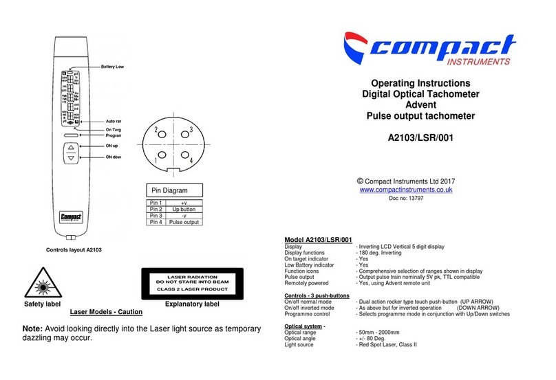
Models A2103 & A2103/LSR features and operation
Common Display features & Specification
Display - Inverting LCD Vertical 5 digit display
Display functions - 180 deg. Inverting
On target indicator - Yes
Low Battery indicator - Yes
Function icons - Comprehensive selection of ranges shown in display
Controls - 3 push-buttons
On/off normal mode - Dual action rocker type touch push-button (UP ARROW)
On/off inverted mode - As above but for inverted operation (DOWN ARROW)
Program control - Selects program mode in conjunction with Up/Down switches
Optical system Model A2103
Optical range - 50mm - 1000mm
Optical angle - +/- 45 Deg. to reflective marker
Light source - Minilamp visible light
Optical system - Laser model A2103/LSR
Optical range - 50mm - 2000mm
Angle of operation - +/- 80 Deg.
Light source - Red Spot Laser Class II
Measurement range - both models
Measurement modes - rpm & rps optically (also Count & Time)
- rpm & rps, metres, yards, feet, per min & per sec, via contact
adaptor
- Count total revs, metres, feet, yards
- Measure Time interval in seconds between pulses (reciprocal rate)
- Speed Capture feature - Maximum, Minimum or Average rate

Page 6
Speed range - Optical mode - 3 - 99,999 rpm (or equivalent in rps)
Contact mode - Max. 50,000 rpm for 10 sec (or equivalent in rps)
Linear speeds - maximum - 0.30 - 1500.0 Metres or Yds/min. (4,500 ft/min) or equilavent in sec-
onds
Resolution range features - Fully Autoranging up to 0.001digit or +/- 1 digit fixed, User selectable
Accuracy speed modes only - 0.02% +/- 1 digit
Count mode resolution - +/- 0.1 Metres (or equilavent in all ranges)
Time interval mode - 0 - 99999 seconds Autoranging only (max 0.01 resolution)
Timebase standard - 0.8 seconds or time between pulses,whichever is longest
Timebase, Fast modes - 0.1 seconds auto-selection in Maximum or Minimum capture mode
Memory features - Last reading held for 1 minute, Auto Switch Off
- Program settings retained in memory after power down off
Contact adaptor - Included complete with rpm cone & metric wheel assembly (remova
ble)
Ex works setting - rpm mode, non autoranging
1. Programming - measurement mode selection
All measurement modes are chosen by this method and once confirmed, selected mode remains in
permanent memory until re-programmed by the user.
1.1. To change mode hold programme button on and press up measure button and then release
both buttons, the display will now illuminate all icons, and the current range will flash.
1.2. To select new measurement mode press either up or down button to scan through the
modes, when the required mode icons flash release measure button & press programme
button once to confirm settings.
for non-speed modes the unit is now programmed and read for use.
1.3. To select mx, mn, av. modes continue to scan through each one, if the mode is not re-
quired, stop scan when all three icons illuminate continuously, then press programme button
once.
The instrument is now ready to use. Set parameters will be retained until reprogrammed.
2. Optical revolutions speed measurement - rpm or rps.
2.1. Ensure batteries are correctly fitted.
2.2. Attach small reflective target to machine shaft (typically 6mm x 25mm, less for laser version)
2.3. Start machine and point the tachometer towards the target.
2.4. Press and hold either of the on/off buttons to suit application and hold continuously.
2.5. Aim light beam onto target, ensure “on-target” sign is glowing or flashing steadily
2.6. Read off rpm, releasing button will hold last reading.
2.7. Last rpm reading will be held in display for 1 minute.
2.8. Press the On button to zero reading or take another measurement.
3. Contact revolution speed measurement - rpm or rps.
3.1. Fit contact adaptor into the tachometer and ensure a good click fit connection.
3.2. Start machine and make clean contact with the recess in shaft end (wheel can be removed).
3.3. Contact the shaft end via the rubber cone, ensure a steady firm pressure is applied and that
the instrument is in line accurately with the machine shaft.
3.4. Press and hold either up or down measure button as required & read speed
3.5. Releasing the On switch will hold the reading automatically for 1 minute, automatic switch
off.
Page 7
4. Linear contact speeds measurement - metres, yds, feet etc.
4.1. Fit contact adaptor as above.
4.2. Keeping the on button pressed, now place the contact wheel on the moving surface and
read the linear rate, ensure wheel is vertical to the moving surface.
4.3. Releasing the on button will then hold the last reading in the display
for 1 min.
4.4. The instrument retains selected measurement mode for further linear measurements af-
ter switch off until programmed to a different mode.
5. Autorange selection - speed modes only
5.1. While taking a measurement using either up or down measure button, the user can tog-
gle between auto and non-auto mode by pressing the programme button, in the auto
mode, the a icon will illuminate.
6. Average speed monitoring mode - ‘av’ icon.
6.1. Average speed mode - this mode provides a rolling average of the last 8 measured val-
ues.
6.2 Press and hold the On/off button at the forward arrow position and hold continuously
6.3 Aim light beam onto target, ensure “on-target” sign is on at bottom of display screen.
6.4 Take rpm reading.
6.5 Note that the display will illuminate only while measurement is taking place.
6.6 Release on/off button and display will clear - no memory retention is available.
7. Operation of Maximum & Minimum modes Speed Capture functions - mx,mn.
7.1. Having selected the required mode, i.e. Maximum or Minimum, (mx).
7.2. You are now ready to Capture a reading “On Demand” but continuing to operate normally.
7.3. When a capture test is ready to commence, while the Measure button is held On, press
Programme button once, at this point the instrument will switch into high speed Timebase
mode, (0.1 Seconds) and will Capture the highest or lowest reading after pressing the
Programme button.
Releasing the On button will hold the reading and cancel the Capture mode until another
Capture measurement is required, when 7.3. should be repeated.
8. Count measurement mode - cnt
8.1. Select mode as described in Measurement mode selection section
8.2. For rev Counting optically, point the light beam at the target and the instrument will
measure all revs. (pulses) until button is released, the display will hold Count for 1
minute.
8.3. By contact method, fit contact adaptor, press speed cone onto the end of the shaft, the
Instrument will count revs.
9. Linear Length Totalisation measurements - mt, ft, yd -
9.1. Select any linear unit of measurement, press contact wheel onto moving surface and
commence Count by pressing & holding Measure button On, Count will increment until
button is released.
9.2. The displayed value can be scanned through the equivalent values of Metres, Feet,
Yards, Count by pressing the Programming button, the instrument automatically calcu-
lates the appropriate reading.
Note. Measurement Units will be stored in originally programmed parameter e.g. metres.

Page 8
10. Time interval measurement - int
10.1. Select int mode through Measurement selection mode
10.2. This mode allows measurement of Time between pulses from optical system (or contac-
tor).
10.3. Optically the instrument will measure the time in seconds between pulses, useful for cy-
cle timing of reciprocating machinery.
10.4. (Time in seconds per revolution), which equals reciprocal speed.
10.5. Very slow speeds can be measured in this mode below 3 rpm.
11. Display orientation - Inverting function - All modes
11.1. The instrument can be used through 180 deg. rotation (e.g. with the light beam pointing
downward into a machine), the display inverts so that normal reading can take place.
11.2. The UP Button selects normal mode for optical and contact measurements.
11.3. The Down button selects the display inversion mode and the whole display including rel-
evant icons will reverse through 180 degrees allowing access to difficult applications.
Temperature specification and storage (LCD Display)
Operating temperature = 0 to + 50 º C.
Storage temperature = –10 to + 80 º C.
Other manuals for Advent Series
1
This manual suits for next models
3
Table of contents
Other Compact Instruments Measuring Instrument manuals

Compact Instruments
Compact Instruments Advent A2101 User manual

Compact Instruments
Compact Instruments A2105 User manual

Compact Instruments
Compact Instruments A2103/LSR/001 User manual

Compact Instruments
Compact Instruments A2106 User manual

Compact Instruments
Compact Instruments Advent Series User manual