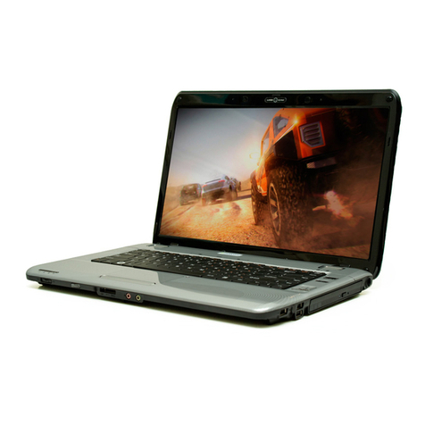
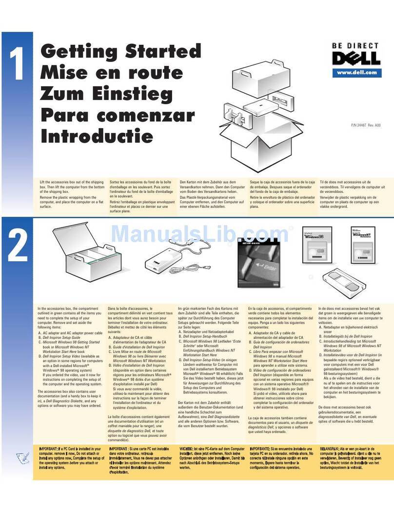
Compal PCM10 User manual

About this User’s Manual
This user’s manual is designed to let you easily find the information you need to get the most from
your notebook.
Introduces you to the features of your notebook.
Gives you the useful details on using your notebook.
Tells you how to look after your notebook, whether at home or traveling.
Introduces you to BIOS, the nervous system of your notebook, and how to change its
fundamental settings.
There is no need to read the manual from the beginning to end. Sim ly find your way to the section
that interests you using the table of contents, or browse through the manual.
You will come across the following icons in this manual:
Hel ful ointers and tricks to get more from your notebook
To hel you note and avoid ossible damage to your notebook’s hardware or software,
or loss of your work
Points out ossible damage to ro erty, ersonal injury or death
Information in this document is subject to change without notice.
© Com al Electronics, Inc. 2011. All rights reserved.
Trademarks used in this document: Microsoft and Windows are registered trademarks of Microsoft
Cor oration.
Other trademarks and trade names may be used in this document to refer to either the entities
claiming the marks and names or their roducts.

1
S ecifications ........................................................................................................................... 10
Cha ter 1 Introducing Your Notebook ....................................................................................... 13
Front and Rear Side ......................................................................................................... 14
1.1.1 Power Key Buttons.................................................................................. 15
1.1.2 Power LED (Blue)( )........................................................................ 15
1.1.3 Battery LED (Blue/Amber) ( )............................................................... 15
1.1.4 HDD accessing state Blue LED ( ) ..................................................... 15
1.1.5 Ca s Lock LED (White) ........................................................................... 15
Left Side........................................................................................................................... 16
1.1.6 AC Ada ter Connector ............................................................................. 17
1.1.7 USB Ports................................................................................................ 17
Right Side ........................................................................................................................ 18
1.1.8 USB Ports................................................................................................ 19
1.1.9 Kensington Lock( ) .................................................................................. 19
1.1.10 AC Ada ter Connector ............................................................................... 19
1.1.12 LAN (RJ-45) .............................................................................................. 19
1.1.13 VGA Port ................................................................................................... 19
Back Side......................................................................................................................... 20
1.1.14 Battery latch Knob ..................................................................................... 20
Cha ter 2 Caring for Your Notebook ......................................................................................... 21
2.1 Caring for Your Notebook ........................................................................................... 22
2.1.1 Cleaning Your Notebook and Keyboard ........................................................... 23
2.1.2 Cleaning the Dis lay ....................................................................................... 23
2.1.3 Cleaning the Touch Pad .................................................................................. 23
2.1.4 Precautions..................................................................................................... 23
2.2 Traveling .................................................................................................................... 25
2.2.1 Identifying Your Notebook................................................................................ 26
2.2.2 Packing Your Notebook ................................................................................... 26
2.2.3 Travel Ti s....................................................................................................... 26
2.2.4 If Your Notebook is Lost or Stolen.................................................................... 26
Cha ter 3 Peri herals............................................................................................................... 28
3.1 SD/MMC/MS Cards .................................................................................................... 29
3.1.1 Installing a SD/MMC/MS Card ......................................................................... 30
3.1.2 Remove a SD/MMC/MS Card.......................................................................... 30
Cha ter 4 The BIOS Setu Program ......................................................................................... 31
4.1 Introduction ................................................................................................................ 32
4.2 Navigating through the BIOS Setu Program .............................................................. 33
4.3 System Controls ......................................................................................................... 34
4.3.1Buttons ............................................................................................................ 34
4.4 Core BIOS Features ................................................................................................... 35
4.5 Thermal management................................................................................................. 36
4.6 Power Management for ACPI mode............................................................................ 37
4.6.1Introduction ...................................................................................................... 37
4.6.2 System Time-outs............................................................................................ 37
4.6.3 System Power Management............................................................................ 37
4.6.4 Device Power Management............................................................................. 37
4.6.5 Hibernation ..................................................................................................... 39
4.7 ACPI (Advanced Configuration and Power Interface) .................................................. 40
4.7.1Introduction ...................................................................................................... 40
4.7.2 ACPI Slee Status........................................................................................... 40
2
4.7.3 Fast Resume................................................................................................... 40
4.7.4 Power State Transition Diagram ...................................................................... 40
4.7.5 Storage Devices and Batteries......................................................................... 41
4.7.6 Bootable Device .............................................................................................. 41
4.7.7 Embedded controller ....................................................................................... 41
4.8 PC2001 ...................................................................................................................... 42
4.9 Miscellaneous Features.............................................................................................. 43
4.9.1BIOS ROM....................................................................................................... 43
4.9.2 USB Su ort ................................................................................................... 43
4.9.3 Flash utility – one BIOS ROM only................................................................... 43
4.9.4 Crisis Recovery ............................................................................................... 43
4.9.5 VGA Su ort ................................................................................................... 43
4.9.6 Fast Boot ........................................................................................................ 44
4.9.7 Wireless Control.............................................................................................. 44
4.10 Customer S ecific Features...................................................................................... 45
4.10.1Dis lay of System Ty e and BIOS Version Number on Boot ........................... 45
4.10.2 CMOS RAM management ............................................................................. 45
4.10.4 EEPROM ...................................................................................................... 46
4.10.5 OEM Active 1.0/2.0/2.1 and KMS activation Su ort...................................... 47
4.10.6 Multi Customer Logo Su ort ........................................................................ 47
4.11 System Setu ........................................................................................................... 48
4.11.1Invoking setu ................................................................................................ 48
4.11.2 Main Menu .................................................................................................... 48
4.11.3 Advanced ...................................................................................................... 49
4.11.4 Security Menu ............................................................................................... 50
4.11.5 Boot Menu..................................................................................................... 52
4.11.6 Exit Menu ...................................................................................................... 53
4.12 OS Com atibility....................................................................................................... 55

3
Safety Instructions
Use the following safety guidelines to hel rotect yourself and your notebook.
General Warnings
Do not o erate your ortable com uter for an extended eriod of time with the base resting
directly on your body. With extended o eration, heat can otentially build u in the base.
Allowing sustained contact with the skin could cause discomfort or, eventually, a burn.
Excessive sound ressure from ear hones or head hones can cause hearing damage or loss.
Please adjustment of the volume control as well as the equalizer to settings other than the
center osition may increase the ear hones or head hones out ut voltage, and therefore the
sound ressure level.
Do not attem t to service the com uter yourself. Always follow installation instructions closely.
To avoid ersonal injury from electric shock or fire:
- Com letely ower down the com uter when re lacing memory modules, cleaning the
com uter, its com onents, or chassis, or erforming o erations requiring similar ste s. To do
this, first turn the ower off at the ower switch, remove the battery, and then disconnect the
AC ada ter from the electrical outlet or from any other ty e of external ower source, such as
an external battery.
- Do not o erate the com uter near water, for exam le, near a bathtub, kitchen sink or
laundry tub, in a wet basement, by a swimming ool, or in the rain.
- Do not connect or disconnect any cables or erform maintenance or reconfiguration of
this roduct during an electrical storm.
- Avoid using the wired LAN during an electrical storm, as a remote risk of electric shock
from lightning exists.
- Do not ush objects into the air vents or o enings of your notebook or accessories. Doing
so can short out interior com onents and may cause fire or electric shock.
- When installing memory modules, ground yourself by touching a grounded conductive
surface, such as a device with a grounded lug. Avoid touching the ins and leads on the
memory module or internal circuitry of the com uter.
When setting u the com uter for work, lace it on a level surface.
Handle com onents with care. Hold a com onent such as a memory module by its edges, not
its ins.
If the battery ack leaks and the fluid get in your eyes, do not rub them. Instead, rinse your
eyes with clean running water and immediately seek medical attention. Otherwise, eye injury

4
may be resulted.
If acid leaking from the battery ack contacts your skin or clothing, immediately wash it away
with the running water. Otherwise, the skin inflammation may occur.
O erate the com uter at the recommended tem erature range of 5 ℃ to +35℃ (+41℉ to
+95℉). Store it at a tem erature of -20℃ to +60℃ (+4℉ to +140℉).
Fan may cause hazardous to your body when it is running, lease kee your body arts out of
the motion ath.
Power Cord & Adapter Warnings
See the installation instructions before connecting to the ower su ly.
Use only the ower cord indicated in this manual.
Power cord sets for use in other countries must meet the requirements of that country. Use the
a ro riate AC ada ter and ower cord for your locale.
If you use an extension cord with your AC ada ter, ensure that the total am ere rating of the
roducts lugged into the extension cord does not exceed the am ere rating of the extension
cable.
When using your ower cord, make sure to osition it around objects so it will not be cut or
unctured.
When you disconnect a cable, ull on its connector on its strain relief loo , not on the cable
itself. As you ull out the connector, kee it evenly aligned to avoid bending any connector
ins. Also, before you connect a cable make sure both connectors are correctly oriented and
aligned.
Be sure that nothing rests on your AC ada ter’s ower cable and that the cable is not located
where it can be tri ed over or ste ed on.
Use only the AC ada ters that are a roved for use with this com uter. Use of another ty e of
ada ter may risk fire or ex losion.
Before you connect the com uter to a ower source, ensure that the voltage rating of the AC
ada ter matches that of the available ower source.
- 115 V/60 Hz in most of North and South America and some Far Eastern countries such as
South Korea and Taiwan.
- 100 V/50 Hz in eastern Ja an and 100 V/60Hz in western Ja an.
- 230 V/50 Hz in most of Euro e, the Middle East, and the Far East.
- If you use an extension cable with your AC ada ter, ensure that the total am ere rating of

5
the roducts lugged in to the extension cable does not exceed the am ere rating of the
extension cable.
Place the AC ada ter in a ventilated area, such as a deskto or on the floor, when you use it to
run the com uter or to charge the battery. Do not cover the AC ada ter with a ers or other
items that will be reduced to cool; also, do not use the AC ada ter while it is inside a carrying
case.
Disconnect ower cords and cables by gras ing the connector, not by ulling on the cable
itself. As you ull out the connector, kee it evenly aligned to avoid bending any connector
ins. Before you connect a cable, lease make sure both connectors are correctly aligned.
To remove ower from the com uter, turn it off, remove the battery, and disconnect the AC
ada ter from the electrical outlet.
The socket outlet must be near to the unit and easily accessible.
Ada ter information:
In ut voltage: 100-240Vac
In ut frequency: 50-60Hz
Rating out ut current: 3.42A (65W)
Rating out ut voltage: 19Vdc
AC ada ter lug is 3 in
Battery Pack Warnings
Please kee the following items because it can be the cause of the burn, fire, and ex losion:
- Inquire (advise) of the manufacturer or seller immediately when the battery is too swelled
to be observed by the naked eye and because this kind of battery can be dangerous.
- Use the certified charger.
- Do not ex ose to inside of car in summer.
- Do not lace on the quilt, electric- a er floor or car et for long time.
- Do not kee into sealed lace as owered on
- Make sure not the terminals of battery to contact with the metals such as necklace, coin,
key or wrist watch.
- Use the lithium secondary battery warranted by the manufacturer of ortable devices.
- Do not im act on the battery abnormally, for exam le, the act of dro ing from on the high
site.
- Do not ex ose into high tem erature more than 60°C
- Do not carry a battery in your ocket, urse, or other container where metal objects (such
as car keys) could short-circuit the battery terminals. The resulting excessive current flow can

6
cause extremely high tem eratures and may result in damage from burns.
- Danger of ex losion may occur if battery is incorrectly re laced. Re lace only with the
same or equivalent ty e battery recommended by the manufacturer.
- Do not dis ose of batteries in a fire. They may ex lode. Check with local authorities for
dis osal instructions.
- Do not use or leave the battery ack near a heat source. Heat can melt the insulation and
damage other safety features, ossibly leading it to leak acid, overheat, emit smoke, burst
and/or ignite.
- Do not immerse the battery ack in water or allow it to get wet. Its rotective features can
be damaged. Abnormal chemical reactions may occur, ossibly leading it to leak acid,
overheat, emit smoke, burst and/or ignite.
- Do not crush, disassemble, uncture, or incinerate the short external contacts of a battery
ack.
- Do not connect the ositive (+) and negative (-) terminals with a metal object such as wire.
Short-circuiting may occur leading the battery ack to leak acid, overheat, emit smoke, burst
and/or ignite.
- Do not use an a arently deformed or damaged battery ack, which may leak acid,
overheat, emit smoke, burst and/or ignite.
- If the battery ack leaks, gives off a bad odor, generates heat, becomes discolored or
deformed, or in any way a ears abnormal during use, recharging or storage, immediately
remove it from the com uter or charger and sto using it.
Battery Pack Disposal
- Dis ose of the lithium ion battery acks at a roved dis osal sites only. To locate an
a ro riate site, contact the solid waste dis osal officials where you live or look for a
rechargeable battery recycling website that lists dis osal locations near you.
- Do not dis ose of battery acks in a fire, throw them in a trash rece tacle, ut them in a
recycling bin not intended for their dis osal, or otherwise discard them in a manner that may
result in their being hazardous to the environment.
Important Safety Instructions
Read these instructions carefully and save them for reference in future.
1.
Follow all warnings and instructions reminded you about this roduct.
2. Un lug this roduct from the wall outlet before cleaning. Do not use liquid cleaners or
aerosol cleaners. Use a dam cloth for cleaning.
3.
Do not use this roduct near water.
4.
Do not lace this roduct on an unstable cart, stand, or table. It may be broken to cause

7
some serious damage of itself.
5.
Slots and o enings in the cabinet and the back or bottom are rovided for ventilation. To
ensure reliable o eration of the roduct and to rotect it from overheating, and also do not
block or cover these o enings. Avoid lacing the roduct on a bed, sofa, rug, or similar
surface to revent from blocking these o enings. This roduct should never be laced
near or over a radiator or a heat register, or in an enclosure unless ro er ventilation is
rovided.
6.
This roduct should be o erated from the ty e of ower indicated on the marking label. If
you are not sure the ty e of ower available, consult your dealer or local ower com any.
7.
Do not allow anything to rest on the ower cord. Do not locate this roduct where eo le
will ste on the cord.
8.
If an extension cord is used with this roduct, make sure that the total am ere rating of the
equi ment lugged into the extension cord does not exceed the extension cord am ere
rating. Also, make sure that the total rating of all roducts lugged into the wall outlet does
not exceed the fuse rating.
9. Never ush objects of any kind into this roduct through cabinet slots as they may touch
dangerous voltage oints or short-out arts that could result in a fire or electric shock.
Never s ill any kind of liquid on the roduct.
10. Do not attem t to service this roduct by yourself. As o ening or removing covers, you will
be ex osed to the dangerous voltages or other risks. Refer all servicing to qualified
service ersonnel.
11. Un lug this roduct from the wall outlet and refer servicing to qualified service ersonnel
under the following conditions:
a. When the ower cord or lug is damaged or frayed.
b. As liquid is s illed into the roduct.
c. The roduct is ex osed to rain or water.
d. If the roduct does not o erate normally when the o erating instructions are followed,
adjust only those controls that are covered by the o erating instructions. Im ro er
adjustment of other controls may result in damage and will often require extensive work by
a qualified technician to restore the roduct to normal condition.
EMC Regulatory Infor ation
This roduct is designed and tested to com ly with the following related EMC (Electromagnetic
com atibility) standards.
FCC Notice

8
“Declaration of Conformity Information”
This equi ment has been tested and found to com ly with the limits for a Class B digital device,
ursuant to Part 15 of the FCC Rules. These limits are designed to rovide reasonable rotection
against harmful interference in a residential installation.
This equi ment generates uses and can radiate radio frequency energy .If the equi ment is not
installed or used in accordance with the instructions; it may cause harmful interference to radio
communications. However, there is no guarantee that interference will not occur in a articular
installation. If this equi ment does cause harmful interference to radio or television rece tion,
which can be determined by turning the equi ment off and on, the user is encouraged to try to
correct the interference by one of following measures:
1 Reorient or relocate the receiving antenna.
2 Increase the se aration between the equi ment and the receiver.
3 Connect the equi ment into an outlet on a circuit different from that to which the receiver is
connected.
4 Consult the dealer or an ex erienced radio/TV technician for hel .
5 This device com lies with Part 15 of the FCC Rules. O eration is subject to the following two
conditions:
(1) This device may not cause harmful interference.
(2) This device must acce t any interference received, including interference that may
cause undesired o eration.
Canadian Notice (Canada nly)
Norwegian Notice (Norway nly)
For Class I equi ment: In Norway, it intend to be connected to CABLE DISTRIBUTION SYSTEMS,
the screen of a coax cable is required to be galvanic isolated from the rotective earth. The
Norwegian text is that “Må kun tilko les kabel-TV nett via galvanisk isolator.”
CE Notice (European Union)
EU Declaration of Conformity

9
BSMI Notice (Taiwan Only)
Most Com al com uter roducts are classified by the Bureau of Standards, Meteorology and
Ins ection (BSMI) as Class B information technology equi ment (ITE).
This (marked on the roduct) indicates the roduct com lies with the BSMI
standard.
BSMI 通告
通告通告
通告 (僅限於台灣地區
僅限於台灣地區僅限於台灣地區
僅限於台灣地區)
如果您在電腦的底部、側面或背面板上找到一個 標誌,則適用於以下部
份的相關規定:

10
Specifications
CPU
AMD ZACATE (1.6G /dual core, 1.5G/Single core,40nm /18W APU/FT1 BGA)
AMD ONTARIO(1.2G / Single core, 1.0G/dua core,40nm /9W APU/FT1 BGA)
Chipset
Hudson M1(A13)
Memory
Su ort 2 SODIMMS DDR3 800Mhz/1066MHz 1G/2G module Max4G
Display
13.3”16:9 W W/LED HD Glare 1366*768
Audio
HD Audio, 2 x S eakers, Micro hone-in and head hone-out
1 x Internal Micro hone su ort
Camera ( ption)
0.3 M and 1.3M Pixel CMOS Camera w/ USB2.0 interface
Keyboard
86/87 keys su ort with 101/102 key emulation without stick- oint.
Vista key, A lication key
Standard itch, 2.45mm travel length.
Multi-Language su ort.
Hard Disk Drive (HDD)
9.5mm, 2.5" SATA HDD 250G/320G/500G(5400r m/7200r m )
ptical Disc Drive ( DD)
N/A
Communication
LAN: 10/100 LAN, 1000 Giga LAN (o tion)
WLAN+BT combo card: 802.11BGN +BT2.1(WLAN-AMP enabled for BT3.0
com atible) (o tion)
Wireless LAN: 802.11 b/g, 802.11 b/g/n via Mini-Card ( o tion)
Pointing Device
Touch ad with u /down scroll zone and two buttons
Su ort Multi Touch for Windows 7
Flash card reader
3-in-1 Card Reader (SD, MMC, MS), don’t su ort XD card

11
I/ Ports
USB 2.0 x 3 (No Power USB feature), HDMI x 1 ,
RGB: VGA ort x 1
Micro hone-in x 1, Head hone-out × 1, DC-in jack ,
Kensington lock x 1
3-in-1 Flash Card Reader(SD/MMC/MS) x 1
Internal micro hone x 1
RJ45 x 1
System Status Indicators
1 K/B indicators: Ca s Lock (White)
1 Power Button LED (White)
1 LED for IDE HDD activity (Blue)
1 LED for System status (Power On / Sus end) (Blue)
1 LED for Battery status (Charging / Full / L1 / L2) (Blue /Amber)
1 LED for Blue tooth/Wireless Card (Blue)
Control Button
Power button (su ort software off, 4 sec)x 1
Magnetic lid switch control for system standby/wakeu
AC Adapter
65W with 19V DC/3 in 240V AC cable
Battery
4-cell Li-On, 18650 ty e, 2600mAh, 2250mAh. 8-cell ,18650t ye,5200mAh
Life Cycle: 70% Design Ca acity after 300 Cycles in 25degreeC
Software
Insyde BIOS
Sus end to DRAM/HDD
Security: Power-On Password, Su ervisor Password
HDD assword
USB memory Boot su ort
Su ort SMBIOS 2.4, PCI2.2
Su ort PXE
Wake on LAN from S3
Wake on LAN from S4 /S5 in AC mode
OS
Windows 7 Ultimate (32bit) / (64bit)

12
Mini Card
One mini-card (WLAN x1) (O tion)
Security
BIOS Password / Kensington lock
Regulatory
EMI: FCC-B, CE,VCCI, BSMI
Safety: Com liant to UL, CB, BSMI
Energy Star /WHQL LOGO
Environment
Tem erature: O erating: 5 - 35°C / Storage: -20 - 65°C
Humidity: 10 - 90% without condensation.
Altitude: O erating sea level u to 10,000 ft
Storage sea level u to 40,000 ft
Thermal
No throttling occur with running ThermNow 80% or 3DMark06 at 28℃ and no shut
down at 35℃.
Thermal rotection
HW thermal rotection:
Shutdown system ( Thermister for CPU ) :
TBD +/-3°C (local tem erature of PCB)
( will define it with real system)
Shutdown system ( Thermister for Battery ) :
TBD +/-3°C (local tem erature of PCB)
( will define it with real system )
CPU thermal rotection
Throttling : HTC enabled
Shutdown : 125°C (T-junction of CPU)
SW shutdown: 100°C (Tj)
Acoustic noise
42 dBA for Llano CPU @35°C.

13
Chapter 1
Introducing Your Notebook

14
Front and Rear Side
The following icture shows the front side of your notebook.
1
Web Camera
5
Battery(Blue/Amber)
2
Ca s Lock(White)
6
HDD(Blue)
3
Micro hone
7
Wireless Status(Blue)
4
Power(Blue)
8
Power Button(White)

15
1.1.1 Power Key Buttons
Press to turn your notebook on.
Windows 7, which comes reinstalled, goes into the shutdown sequence
automatically if you ress the ower button while on.
In Windows 7, you can configure this in Control Panel > System and Maintenance or
Hardware and Sound > Power O tions > Change lan settings > Change advanced
ower settings.
1.1.2 Power LED (Blue)( )
Power LED and Sus end LED indicate the systems ower states by user combinations, The
flashing Power On LED indicates your notebook is in standby mode.
1.1.3 Battery LED (Blue/Amber) ( )
Battery states LED is one dual-color LED indicator both of Blue and Amber color.
1.1.4 HDD accessing state Blue LED ( )
Reflect the activities of Blue Led.
Note: LED is controlled directly by hardware.
1.1.5 Caps Lock LED (White)
Ca s lock LED (White): Ca s Lock State of Keyboard
NOTE: In normal mode (Cursor and Num function are disable), when users ress Hot Key, the
Cursor LED will be on. When users ress Hot Key, the Cursor LED will be off.

16
Left Side
The following icture shows the left side of your notebook.
1
DC-IN
2
USB 2.0
3
USB 2.0
4
Micro hone(Black)
5
Head hone(Black)

17
1.1.6 AC Adapter Connector
Use this connector to attach the AC ada ter to your notebook. You can con
nect an
AC ada ter when your notebook is switched on or off.
While the AC ada ter works with electrical outlets worldwide, ower connectors and
ower stri s vary by country. Ensure you use a com atible cable or correctly
connect the cable to the ower stri or electrical outlet. Failure to do so may cause
fire or damage to equi ment.
1.1.7 USB Ports
Use this ort to connect a USB device, such as a mouse, external keyboard, or
rinter to the com uter.
USB is a eri heral ex ansion standard that su orts data-transfer rates u to 480
Mb s. USB eri herals have a single standard for cables and connectors. You can
install and remove USB devices while the com uter is on. This is called “hot
swa ing”.

18
Right Side
The following icture shows the right side of your notebook.
1
Kingston Lock
2
RJ-45
3
D-Sub
4
HDMI
5
USB 2.0
6
3 in 1 Card Reader

19
1.1.8 USB Ports
Use this ort to connect a USB device, such as a mouse, external keyboard, or rinter
to the com uter.
USB is a eri heral ex ansion standard that su orts data-transfer rates u to 480 Mb s.
USB eri herals has a single standard for cables and connectors. You can install and
remove USB devices while the com uter is on. This is called “hot swa ing”.
1.1.9 Kensington Lock( )
A Kensington Security Slot is a small, metal-reinforced hole found on almost all small or ortable
com uter and electronics equi ment, articularly on ex ensive and/or relatively light ones, such
as la to s, com uter monitors, deskto com uters, gaming consoles, and video rojectors. It is
used for attaching a lock-and-cable a aratus, in articular those from Kensington.
1.1.10 AC Adapter Connector
Use this connector to attach the AC ada ter to your notebook. You can
connect an AC ada ter when your notebook is switched on or off.
While the AC ada ter works with electrical outlets worldwide, ower connectors
and ower stri s vary by country. Ensure you use a com atible cable or correctly
connect the cable to the ower stri or electrical outlet. Failure to do so may cause
fire or damage to equi ment.
1.1.12 LAN (RJ-45)
The LAN allows you to connect your notebook to an internet line with a
standard RJ-45 connector.
1.1.13 VGA Port
Use this ort to connect an external monitor to your com uter.
Table of contents
Other Compal Laptop manuals

Compal
Compal ACY25 series User manual

Compal
Compal HEL81 User manual

Compal
Compal Notebook User manual

Compal
Compal Notebook User manual

Compal
Compal HGL-30 Installation instructions

Compal
Compal Notebook User manual

Compal
Compal PBL10 User manual

Compal
Compal Notebook PC User manual

Compal
Compal NTUC0 User manual

Compal
Compal Notebook User manual
Popular Laptop manuals by other brands

IBM
IBM ThinkPad 390/i Series 1700 (2626, 2627) Hardware Maintenance Manual

HANNspree
HANNspree SN10E228U3221 Brochure & specs

Acer
Acer TravelMate C210 Series Service guide

Dell
Dell Inspiron 24 5000 Series Setup and specifications

Toshiba
Toshiba R850-S8550 Specifications

Lenovo
Lenovo ThinkPad Z13 Gen 2 LTE1 user guide