Compliance West LCB-1010-B User manual


Dear Customer:
Congratulations! Compliance West USA is proud to present you with
your LCB-1010-B leakage current measurement instrument. Your
instrument features state-of-the-art accuracy for making leakage current
measurements.
To fully appreciate all the features of your new instrument, we suggest
that you take a few moments to review this manual. Compliance West
USA stands by your instrument with a full one-year warranty. If the need
arises, please don't hesitate to call on us.
Thank you for your trust and confidence.
Rev 2, April 2019


Section 1.....................................................................................................................................................1
An Introduction to leakage current testing with the LCB-1010-B ...............................................1
Safety Precautions........................................................................................................................1
Test Personnel..............................................................................................................................1
Testing Area.................................................................................................................................1
Section 2.....................................................................................................................................................2
LCB-1010-B Configuration .........................................................................................................2
Specifications...............................................................................................................................2
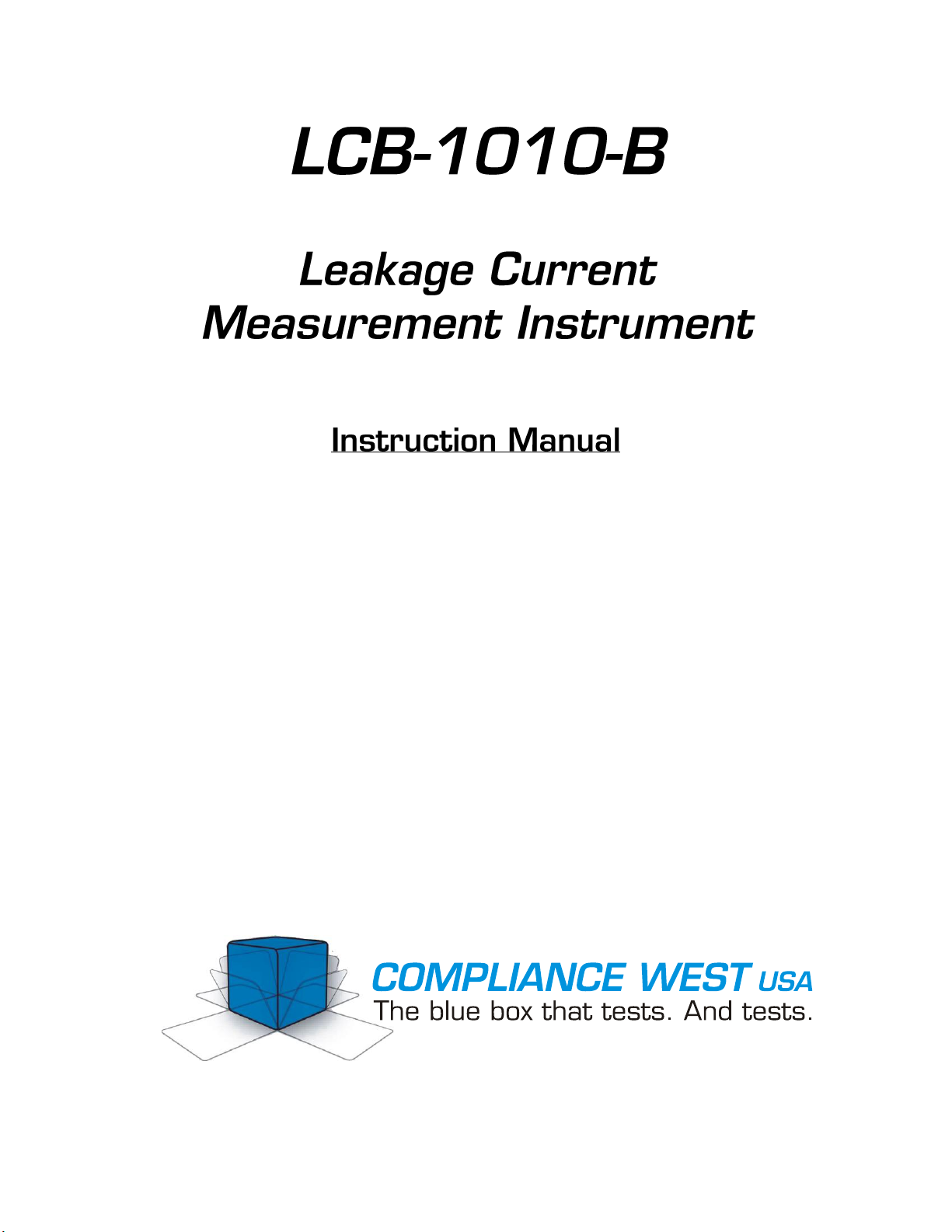
Configuration 1..............................................................................................................2
IEC 61010-1:2010 Fig. A.1 .............................................................................2
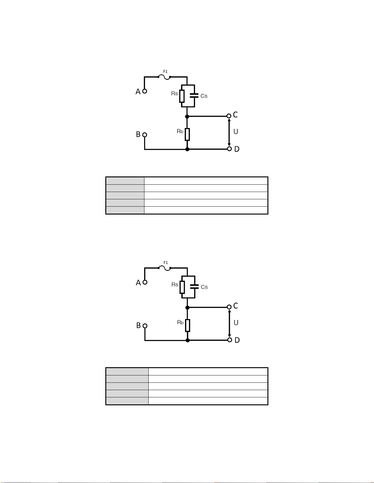
Configuration 2..............................................................................................................3
IEC 61010:2010 Fig. A.3 ................................................................................3
Configuration 3..............................................................................................................3
IEC 61010-1:2010 Fig A.4 ..............................................................................3
Section 3.....................................................................................................................................................4
Operating Instructions..................................................................................................................4
Setting up your Tester..................................................................................................................4
Fuse Verification Check...............................................................................................................5
Verification of Proper Operation..................................................................................................5
Section 4.....................................................................................................................................................6
Maintenance and Calibration .......................................................................................................6
Introduction..................................................................................................................................6
Service Information......................................................................................................................6
General Maintenance ...................................................................................................................6
Cleaning .......................................................................................................................................6
Calibration Information................................................................................................................6
Section 5.....................................................................................................................................................7
Technical Assistance....................................................................................................................7
Appendix A ................................................................................................................................................8
Tolerance comparison for LCB Configuration 1 (Fig.A.1)..........................................................8
Tolerance comparison for LCB Configuration 2 (Fig.A.3)..........................................................9
Tolerance comparison for LCB Configuration 3 (Fig.A.4)..........................................................10

1
Section 1
An Introduction to leakage current testing with the LCB-1010-B
Some amount of leakage current exists in all modern electrical and electronic equipment that connects to an
AC power source. Leakage current is always unintentional: either due to capacitive coupling from the AC
mains circuit to ground (such as exists in AC motors) or as an unintended side effect of EMI suppression
components (such as capacitors connected from AC mains to the chassis of the equipment). The amount of
leakage current and the measurement methods are governed by various end-product safety standards. These
standards often refer to the international standard IEC 60990 - Methods of Measurement of Touch Current
and Protective Conductor Current and other standards (i.e. IEC 61010) for the design and specification of the
leakage current measurement network.
Compliance West USA offers several different leakage current networks to perform testing to numerous end-
product standards. These networks comply with the requirements of the International Committee of Testing
Laboratories Operational Procedure 113 (IECEE CTL-OP 113 Ed. 1.1). This document outlines
requirements for design, calibration, and frequency response of the leakage measurement instrument.
The Compliance West USA LCB leakage current measurement instruments are leakage current networks
only - they must be used with a suitable voltmeter to perform leakage current measurements. The voltmeter
used can significantly affect the results of the measurement. The voltmeter used must have adequate
frequency response to measure the AC leakage-current voltages, and have an input impedance of 1 Megaohm
or greater.
Safety Precautions
Leakage current testing is inherently dangerous because the Equipment Under Test (EUT) is generally
ungrounded during testing. In some safety standards, an additional single-fault condition is introduced during
leakage current testing, which may expose the test operator to hazardous or even lethal voltages.
Test Personnel
Test operators must be properly trained in the procedures for safety performing leakage current testing. Metal
jewelry should not be work during testing. Operators should not allow others into the testing area, especially
when tests are being conducted. Organization is to be stressed. The operator should keep the test area free
of unused leads and equipment.
Testing Area
The area used for conducting leakage current tests should be as remote as possible from normal production
line activities. Only personnel conducting the test should be allowed in the area, and it should be taped or
roped off to preclude casual entry by other employees. In addition, the area should be marked "WARNING
- HIGH VOLTAGE TESTING" or the equivalent to warn others of the nature of the testing taking place.
The bench being used should be non-conductive, and any exposed metal parts should be tied together and
grounded.

2
Section 2
LCB-1010-B Configuration
This manual contains a description of the three configurations that make up your LCB-1010-B instrument.
Each configuration contains only one leakage current network.
Your instrument is warranted for a period of one year upon shipment of the instrument to the original
purchaser.
Specifications
Each network configuration includes an input fuse to protect against excessive current that could damage the
leakage current network. If the LCB-1010-B is used incorrectly, the internal fusing may not protect the
internal network components from damage. Such damage is not covered under warranty. For continued
protection against risk of fire or electric shock, replace the internal fuse only with a type and rating as
specified in this manual.
Voltage Rating
0-264Vrms AC to enclosure, O.V. Cat II, 50-440Hz at input terminals1
Current Rating
100mA maximum
Fuse Rating (F1)
Littelfuse 370 series, type TR5, rated 63mA, 250V, fast-acting2
Environmental
10-90°rH, non-condensing; 0-2000m altitude; 10-40°C
Components
High-frequency, low-parasitic, individually selected to maintain
+/- 1.0% tolerance
Frequency Response3
50-60 Hz: +/- 3.5% accuracy
>60 Hz –1MHz: +/- 5% accuracy
Note 1: Current exceeding the current rating will cause the fuse to open
Note 2: Fuse is specified to hold for 1 hour (not open) at 150% of the fuse current rating
Note 3: LCB observed accuracy is in accordance with CTL Decision Sheet no. DSH 251b and e. See
Appendix A for tolerance graphs.
Configuration 1
IEC 61010-1:2010 Fig. A.1
Table 1 Configuration 1 Specifications
A, B
Input terminals to connect to EUT
Rs
1500 Ohm
Cs
0.22 uF
Rb
500 Ohm
R2
10 kOhm
C3
0.022 uF
U1, U2, COM
Output terminals for connection to voltmeter

3
Configuration 2
IEC 61010:2010 Fig. A.3
Table 2 Configuration 2 Specifications
A, B
Input terminals to connect to EUT
Rs
1500 Ohm
Cs
0.22 uF
Rb
500 Ohm
C, D
Output terminals for connection to voltmeter
Configuration 3
IEC 61010-1:2010 Fig A.4
Table 3 Configuration 3 Specifications
A, B
Input terminals to connect to EUT
Rs
375 Ohm
Cs
0.22 uF
Rb
500 Ohms
C, D
Output terminals for connection to voltmeter

4
Section 3
Operating Instructions
This section describes how to set up and make measurements with your instrument. We recommend that you
read the entire section carefully so that you can use all the features of your instrument.
Setting up your Tester
Your LCB leakage current measurement instrument is shipped with three cables that connect to detachable
terminal blocks on the input and output side on the front of the instrument. One end of each cable is
connected to a detachable terminal block as shown in Error! Reference source not found. below. The other
end of each cable is unterminated: these wires should be connected to the EUT and the voltmeter to the output
connector. Note that these cables may be disconnected from the terminal blocks if you choose to use other
test leads.
Figure 1 Test lead wiring
The provided test cables are shielded, and the cable shield is connected to the metal enclosure of the LCB
instrument. The shielded cables may be left unterminated or grounded as needed for testing.

5
Fuse Verification Check
To check the fuse, connect an ohmmeter between Aand B. An open circuit measurement indicates an open
fuse, and the fuse must be replaced before use.
Verification of Proper Operation
Once your LCB has successfully passed the fuse verification, you can proceed to perform a verification of
proper operation, for this matter use a DC ohmmeter. Please refer the following table to know the
measurements points and the expected value depending on your LCB configuration. If any of your
measurements are out of tolerance, please contact the manufacturer for further assistant.
Table 4 LCB Verification Points and Values
LCB
Measurements points
Expected Value (Ω)
Tolerance (Ω)
Config 1
(Fig.A.1)
A-U1
1500
1485 - 1515
U1-B
500
495 - 505
A-B
2000
1980 - 2020
U1-U2
10000
9900 - 10100
Config 2
(Fig.A.3)
A-B
2000
1980 - 2020
A-C
1500
1485 - 1515
C-D
500
495 - 505
Config 3
(Fig.A.4)
A-C
375
371.25 - 378.75
A-B
875
866.25 - 883.75
B-C
500
495 - 505
A-C
375
371.25 - 378.75

6
Section 4
Maintenance and Calibration
WARNING
MAINTENANCE AND CALIBRATION INSTRUCTIONS ARE FOR QUALIFIED PERSONNEL
ONLY. TO AVOID ELECTRIC SHOCK, DO NOT PERFORM ANY SERVICING OTHER THAN
THE CONTAINED IN THE OPERATING INSTRUCTIONS.
Introduction
This section of the manual contains maintenance information for the LCB leakage measurement instrument.
A 1-year calibration cycle is recommended to maintain the specifications of the factory.
Service Information
The LCB tester is warranted to the original purchaser for a period of 1 year. This warranty does not cover
problems due to misuse or neglect. Malfunctions which occur within the limits of the warranty will be
corrected at no charge. Mail the instrument postpaid to the manufacturer. Dated proof of purchase is required
for all in-warranty repairs. The manufacturer is also available for calibration and / or repair of instruments
that are beyond their warranty period. Contact the manufacturer for a cost quotation. Ship the instrument and
your remittance according to the instructions given by the manufacturer.
General Maintenance
To avoid contaminating the PWB with oil from your fingers, handle it by the edges or wear gloves. If the
PWB becomes contaminated, refer to the cleaning procedures given later in this section.
WARNING
Remove all external connections before opening the LCB. Do not connect the LCB to hazardous live
circuits with the internal circuitry exposed.
Cleaning
CAUTION
Do not use aromatic hydrocarbons or chlorinated solvents for cleaning. These solutions will react with
the plastic materials used in the instrument.
Clean the exterior of the LCB with a mild solution of detergent and a damp sponge. Clean dust from the PWB
with clean, dry, low pressure (<20 psi).
Calibration Information
The Calibration Procedure should be performed annually and any time the instrument has been repaired. The
calibration procedure should be performed at an ambient temperature of 23C 5C (73.4F 9F). The
Calibration procedure must be performed by qualified personnel, for more information contact Compliance
West USA.

7
Section 5
Technical Assistance
Technical Assistance from Compliance West USA is available:
Phone: (800) 748-6224
Hours: 8:00 AM - 4:00 PM Pacific Time.
Also available on our web site at: www.compwest.com
Contact:
Compliance West USA
650 Gateway Center Way, Suite D
San Diego, CA., 92102
United States of America.
Phone: (619) 878-9696
FAX: (619) 794-0404

8
Appendix A
Tolerance comparison for LCB Configuration 1 (Fig.A.1)
Figure A1. Input Impedance vs Frequency
Figure A2. Transfer Impedance vs Frequency
Figure A3. Vout/Vin Ratio vs Frequency
0
500
1000
1500
2000
2500
10 100 1K 10K 100K 1M
Input impedance [Ω]
Frequency [Hz]
Input Impedance
tolerance limts per
CTL DSH 251B
0
100
200
300
400
500
600
10 100 1K 10K 100K 1M
Transfer impedance [Ω]
Frequency [Hz]
Transfer Impedance
tolerance limts per
CTL DSH 251B
0
0.05
0.1
0.15
0.2
0.25
0.3
0.35
10 100 1K 10K 100K 1M
Vout/Vin ratio
Frequency [Hz]
Vout/Vin (for
Calibration)
tolerance limts per
CTL DSH 251B

9
Tolerance comparison for LCB Configuration 2 (Fig.A.3)
Figure A4. Input Impedance vs Frequency
Figure A5. Transfer Impedance vs Frequency
Figure A6. Vout/Vin Ratio vs Frequency
0
500
1000
1500
2000
2500
10 100 1K 10K 100K 1M
Input impedance [Ω]
Frequency [Hz]
Input Impedance
tolerance limts per
CTL DSH 251B
470
480
490
500
510
520
530
10 100 1K 10K 100K 1M
Transfer impedance [Ω]
Frequency [Hz]
Transfer Impedance
tolerance limts per
CTL DSH 251B
0
0.2
0.4
0.6
0.8
1
1.2
10 100 1K 10K 100K 1M
Vout/Vin ratio
Frequency [Hz]
Vout/Vin (for
Calibration)
tolerance limts per
CTL DSH 251B

10
Tolerance comparison for LCB Configuration 3 (Fig.A.4)
Figure A7. Input Impedance vs Frequency
Figure A8. Transfer Impedance vs Frequency
Figure A9. Vout/Vin Ratio vs Frequency
0
100
200
300
400
500
600
700
800
900
1000
10 100 1K 10K 100K 1M
Input impedance [Ω]
Frequency [Hz]
Input Impedance
tolerance limts per
CTL DSH 251B
470
480
490
500
510
520
530
10 100 1K 10K 100K 1M
Transfer impedance [Ω]
Frequency [Hz]
Transfer Impedance
tolerance limts per
CTL DSH 251B
0
0.2
0.4
0.6
0.8
1
1.2
10 100 1K 10K 100K 1M
Vout/Vinratio
Frequency [Hz]
Vout/Vin (for
Calibration)
tolerance limts per
CTL DSH 251B
Table of contents
Popular Measuring Instrument manuals by other brands

Smappee
Smappee Energy monitor-e1 installation manual

Ponsel
Ponsel ACTEON 2020 Redox-Temperature user manual

Gemu
Gemu GEMU 1242 operating instructions

Greyline Instruments
Greyline Instruments DFM-IV user guide

Emerson
Emerson Net Safety Millennium Reference manual

4iiii
4iiii PRECISION Firmware Upgrade Instructions