Compressed Air Advisors Hankison SPXFLOW HPR75 User manual

F39°F
C
OFF
ON
33°
1° C4°
HPR Series
Refrigerated Type Compressed Air Dryers
Models: HPR75, HPR100, HPR125, HPR150, HPR200, HPR250, HPR300, HPR400, HPR500
FORM NO.: 7610.483.42
REVISION: 10/2015 READ AND UNDERSTAND THIS MANUAL PRIOR TO OPERATING OR SERVICING THIS PRODUCT.
INSTRUCTION MANUAL

Contents
GENERAL SAFETY INFORMATION ......................... 1
RECEIVING, MOVING, AND UNPACKING ............... 1
INSTALLATION....................................................... 2
INSTRUMENTATION .............................................. 3
START-UP/OPERATION.......................................... 5
SHUTDOWN.......................................................... 5
MAINTENANCE..................................................... 5
FIELD SERVICE GUIDE........................................... 7
ENGINEERING DATA ............................................. 8
ELECTRICAL SCHEMATICS
Model: HPR75.................................................. 9
Models: HPR100 to HPR125............................ 10
Model: HPR150................................................ 11
Models: HPR200 to HPR500............................ 12
AIR AND REFRIGERANT FLOW SCHEMATICS
Models: HPR75 to HPR150.............................. 13
Models: HPR200 to HPR500............................ 14
REPLACEMENT PARTS.......................................... 15
WARRANTY .......................................................... 17

1
GENERAL SAFETY INFORMATION
1. PRESSURIZED DEVICES:
This equipment is a pressure containing
device.
• Donotexceedmaximumoperating
pressure as shown on equipment
serial number tag.
• Makesureequipmentisdepressurizedbeforeworking
onordisassemblingitforservice.
2. ELECTRICAL:
This equipment requires electricity to
operate.
• Installequipment in compliancewith
all applicable electrical codes.
• Standard equipment is supplied with electrical en-
closures not intended for installation in hazardous
environments.
• Disconnectpowersupplytoequipmentwhenperform-
inganyelectricalservicework.
3. BREATHING AIR:
• Airtreatedbythisequipmentmaynot
besuitableforbreathingwithoutfur-
ther purification.
Refer to applicable standards and
specicationsfortherequirementsfor
breathing quality air.
RECEIVING, MOVING, AND UNPACKING
A. RECEIVING
Thisshipmenthasbeenthoroughlychecked,packedand
inspectedbeforeleavingourplant.Itwasreceivedingood
conditionbythecarrierandwassoacknowledged.
CheckforVisibleLossorDamage.Ifthisshipmentshows
evidenceoflossordamageattimeofdeliverytoyou,in-
sistthatanotationofthislossordamagebemadeonthe
delivery receipt by the carrier’s agent.
B. UNPACKING
Checkforconcealedlossordamage.Whenashipment
has been delivered to you in apparent good order, but
concealed damage is found upon unpacking, notify the
carrier immediately and insist on his agent inspecting the
shipment. Concealed damage claims are not our respon-
sibilityasourtermsareF.O.B.pointofshipment.
C. MOVING
In moving or transporting dryer, do not tip dryer onto its
side.
D. STORAGE
IMPORTANT: Do not store dryer in temperatures above
130°F (54.4°C).

2
Compressor
Oil Removal
Filter
Aftercooler Automatic Drain
Dryer
Separator Receiver
TYPICAL COMPRESSED AIR SYSTEM
INSTALLATION
Ambient Air Temperature
Locate the dryer indoors where the ambient air temperature will
be between 45°F and 110°F. Intermittent operation at ambient
temperatures up to 113°F will not damage the dryer but may
result in a higher dew point or dryer shutdown due to high
refrigerantdischargepressure(seeFieldServiceGuide).
Do not operate air-cooled dryers at ambient air temperatures
below 40°F. Such operation may result in low suction pressure,
causingfreeze-up.
Location and Clearance
Mountthedryeronalevelbase.Ifthebasevibrates,boltthe
unitdownusingvibrationdampeners.Ifthedryerisair-cooled,
installitinaclean,well-ventilatedareatoreducefoulingofthe
condenser coils with dirt and dust. Allow at least 24 inches
clearanceonthesidesandthefrontofthedryerforcooling
airowandforserviceaccess.
System Arrangement
Liquidwaterintheinletairwilladverselyaffecttheperformance
ofthedryer.Installthedryerdownstreamofanaftercooleror
separatorsothatthetemperatureofthedryerinletairdoesnot
exceed120°Fandtheinletairdoesnotcontainanyliquidwater.
Ifthecompressedairowisrelativelyconstantanddoesnot
exceedthedryerowrating,itisrecommendedthatthedryer
belocateddownstreamofthereceivertank.Ifthenatureof
theapplicationissuchthattheairdemandregularlyexceedsthe
dryer flow rating, it is recommended that the dryer be located
upstreamofthereceiver.
Forsafetyandconvenience,installinletandoutletshutoffvalves
anddepressurizationvalves.Thesevalvesallowthedryertobe
isolatedand depressurized forservicing. Bypass piping may
beinstalledaroundthedryerforuninterruptedairowwhen
thedryerisserviced.Ifthecompressedairoperationcannot
tolerateundriedairforshortperiods,installaseconddryerin
the bypass line.
Compressed air systems commonly require filters to remove
compressor oils, particulates, condensed liquids and other
contaminants. When an oil-removal filter is used, it should be
installeddownstreamoftherefrigerateddryer.Atthislocation,
the life of the replaceable lter element is prolonged since
someoftheentrainedoilisremovedbythedryeranddrained
through the separator.
Piping and Connections
Pipingmustbefurnishedbytheuserunlessotherwisespeci-
ed.Connectionsandttingsmustberatedforthemaximum
operating pressure given on the dryer data plate and must be
in accordance with applicable codes. Support all piping; do not
allowtheweightofanypipingtostressthedryerorltercon-
nections.Inlet and outletshutoffvalves and avalved bypass
valvearerecommended.Pipingshouldbeatleastthesizeof
theinletandoutletconnectionstominimizepressuredropin
theairsystem.SeeEngineeringDatasectionfordryerinletand
outlet connections.
Removing Condensate
Condensate must be drained from the dryer to prevent re-
entrainment. The dryers are equipped with automatic drain
valves and internal drain hoses up to the drain connections on
the dryer cabinets. The user must install a separate discharge
lineatthedrainconnectiontocarryoffcondensatetoanenvi-
ronmentally approved condensate collection/disposal system.
Piping or copper tubing 1/2 inch or larger is recommended
forcondensatedischargelines.Installthedrainlinessothat
condensate can be seen as it drains.
Electrical Connections
The dryers are constructed according to NEMA Type 1 electrical
standards. Field wiring must comply with local and national fire,
safetyandelectricalcodes.Installationmustbeinaccordance
with the National Electrical Code. Confirm that your line voltage
isthesameasthevoltagelistedonthedryerdataplate.Refer
toFigure1forelectricalschematics.
Operation of dryers with improper line volt-
age constitutes abuse and could affect the dryer war-
ranty.

3
INSTRUMENTATION
ON/OFF Switch
ThedryerisequippedwithanON/OFFswitchonthefrontpanel.
A light signals when the dryer is on.
Dew Point Indicator
(Models HPR75 through HPR150)
All dryers are equipped with a dew point indicator which indi-
catesdryerconditionsasfollows:
Itisnormalforthedewpointindicatortobeintheredzone
when the dryer is first turned on and then move to the green
zonewhenthedryerreachesitsnormaloperatingtemperature.
If this indicator is in the red zone during normal operation,
turnthedryerofftoavoidcompressordamage.Refertothe
FieldServiceGuideforadditionalinformation,orcallyourlocal
distributor.
Dryer System Monitor (DSM)
(Models HPR200 through HPR500)
The Dryer System Monitor (DSM) has LED type dew point tem-
perature indicators and electronic drain valve timing controls.
When the dryer is running normally, the green LEDs will illumi-
nate.IftheredLEDisilluminated,thereisaneedforthedryer's
operatingconditiontobechecked.
NOTE: When the dryer is turned on, all LEDs will be illuminated.
Allow15minutesfortheredandyellowLEDstobeextinguished.
The automatic drain valve controls allow the period of drain
openingtobesetfrom0.5secondsto9secondsanddrainvalve
closedtimetobesetfrom0.5minutesto9minutes.When
the "PUSH TO TEST" button is pushed, the drain valve opens and
remainsopenfortheadjusted"open"time.
Automatic Drain Valve
All models are equipped with an electronic drain valve that
automatically discharges condensate from the dryer. Drain
valve operation is controlled by a drain valve timer. The drain
openingcanbesetfrom0.5secondsto9seconds.Thedrain
cyclecanbesetfrom0.5minutesto9minutes.
Models HPR75 through HPR150 have the timer mounted directly
on the drain valve. For models HPR200 through HPR500, drain
valveadjustmentsaremadeontheDryerSystemMonitor(DSM).
Electronic Drain Valve Adjustment
Tominimizeairlosses,thedrainvalvecontroltimeshouldbe
adjustedtoopenthedrainportjustlongenoughtodischarge
accumulated condensate. Set the drain valve operating time so
thatonlyairdischargesattheendoftheopenperiod.Recom-
mended initial settings are a 1 to 2 second drain opening and
30secondsdrainclosedtime.Ifliquidstilldischargesastheport
isclosing,setthetimerforashortercycleoralongeropening.
NOTE:Theamountofcondensatewillvaryasambientcondi-
tions and inlet flow rates change.
Dew Point Indicator
(Models HPR75, HPR100, HPR125 and HPR150)
3 4
2
1
5
Drain Timer
(Models HPR75, HPR100, HPR125 and HPR150)
1. Adjustmentknobforthedrainvalveopentime.The
values on the dial correspond to the time in seconds
that the valve is open in each drain cycle.
2. Adjustment knob for the drain valve closed time.
The values on the dial correspond to the time in
minutes that the valve is closed in each drain cycle.
3. LED to indicate when the drain valve is open.
4. Drain test button. When the button is pressed, the
drainvalveopensforthetimecorrespondingtothe
setting on item 1.
5. LED to indicate when the drain valve is closed.

4
2
1
10 9 8
7
6
543
Dryer System Monitor
(Models HPR200, HPR250, HPR300, HPR400 and HPR500)
1. On/Off Switch:Pressthetop of the switch(I)to turn
the dryer on. Press the bottom of the switch (O) to
turnthedryeroff.Whenthedryerison,theswitchis
illuminated.
2. Thisisagraphic symbol for the AirDryercompressor.
It simply indicates that the switch is used to turn the
compressor(dryer)onandoff.
3. Part of the graphic for the dew point temperature
scale. The snowflake indicates the low (cold) end of
the scale.
4. Main portion of the graphic for the dew point tem-
perature scale. Green indicates low, orange indicates
medium, red indicates high.
5. Part of the graphic for the dew point temperature
scale. The thermometer indicates the high (hot) end
ofthescale.
6. Six (6) LEDs that indicate dew point temperature
according to the graphic scale above the LEDs. The
colorofeachLEDmatchesthecoloredbars
7. Adjustmentknobforthedrainvalveopentime.The
values on the dial correspond to the time in seconds
that the valve is open in each drain cycle.
8. Adjustmentknobforthedrainvalveclosedtime.The
values on the dial correspond to the time in minutes
that the valve is closed in each drain cycle.
9. LED to indicate when the drain valve is open.
10. Drain test button. When the button is pressed, the
drain valve opens for the time corresponding to the
setting on item 7.

5
START-UP/OPERATION
Followtheprocedurebelowtostartyourdryer.Failuretofollow
theprescribedstart-upprocedurewillinvalidatethewarranty.If
problems arise during start-up, call your distributor.
RefertoSerialNumberTagfordryeroperating
capacity.Donotexceedrecommendedcapacity.
Drainconnectionsmustbemadebeforethedryercanbeop-
erated.Thedryersarefullyautomaticandrequirenoauxiliary
controls.
1. Turn the dryer ON/OFF switch to OFF.
2. Checkthatthemainelectricalsupplyvoltagematchesthe
voltage specified on the dryer data plate.
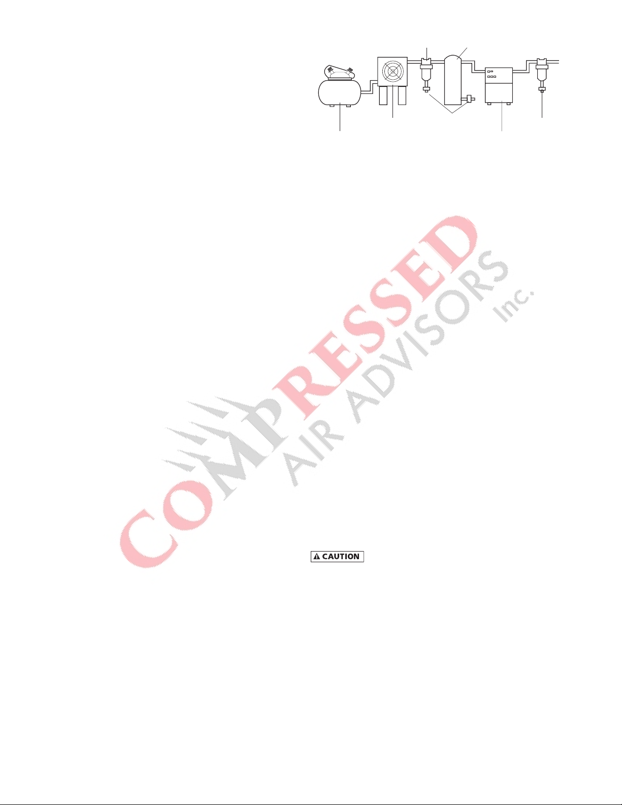
3. Checkproperconnectionandsupportofcompressedair
linestothedryer;checkbypassvalvesystem,ifinstalled.
4. SLOWLYpressurizethedryer.Theoutletvalvesofthedryer
should be closed to prevent flow through the dryer.
5. Turn on the main electrical power to the dryer.
6. Ensureadequateventilationforair-cooleddryers.
To start dryer:
1. Turn the power switch to ON.Therefrigerantcompressor
will turn on.
2. Allow the dryer to run 15 minutes. Confirm that the tem-
peratureindicatorsareinthegreenzone.
3. SLOWLY open the dryer outlet valves permitting flow
through the dryer.
4. Conrmthatcondensateisdischargingfromthedrainvalve
by pressing the "TEST" button.
5. Check drain valve timing. See AUTOMATIC DRAIN VALVE
sectionfordrainvalveadjustmentprocedure.
6. Confirm that the inlet air temperature, pressure and airflow
to the dryer meet the specified requirements (see Engi-
neering Data section).
7. Conrm that the condensate lines from the drain valve
discharge into a collection tank or an environmentally-
approved disposal system.
The dryer is designed to run continuously. Let the dryer run
evenwhenthedemandforcompressedairisinterrupted;the
dryerwillnotfreezeup.
SHUTDOWN
Whenthedryermustbeshutdownformaintenanceorother
reasons,usethefollowingprocedure.
Ifelectricalrepairsmustbemade:
1. Turnoffthepowerswitch.
2. Disconnect the main power supply.
3. LockoutandtagthepowersupplyinaccordancewithOSHA
requirements.
Ifmechanicalrepairsaretobemadeorserviceisperformed,
venttheinternalpressureofthedryertoatmosphericpressure.
Restart the dryer according to the start-up instructions.
Disconnectpowersupplyanddepressurizedryer
beforeservicing.Dismantlingorworkingonanycomponentof
the compressed air system under pressure may cause equip-
mentfailureandseriouspersonalinjury.
MAINTENANCE
The dryers require little maintenance for satisfactory opera-
tion.Gooddryerperformancecanbeexpectedifthefollowing
routinemaintenancestepsaretaken.
Dismantlingorworkingonanycomponentofthe
compressed air system under pressure may cause equipment
failureandseriouspersonalinjury.Beforedismantlinganypart
ofthe dryer or compressed air system, completely ventthe
internal pressure to the atmosphere.
General
Forcontinuedgoodperformanceofyourrefrigerateddryer,
allrefrigerationsystemmaintenanceshouldbeperformedby
acompetentrefrigerationmechanic.
NOTE:Beforecorrectivemaintenanceisdoneduringthewar-
ranty period, call your local distributor and proceed according to
instructions.Refertothewarrantyforlimitsofyourcoverage.
Daily Maintenance
Checktheoperationoftheautomaticdrainvalveatleastonce
daily.SeetheFieldServiceGuideforremediestodrainvalve
malfunctions. See the AUTOMATIC DRAIN VALVE section for
drainvalveadjustment.
Weekly Maintenance
Inspecttheambientairlterweeklyandcleanitifnecessary.
Dirtyairlterscauselossofefciencyandmayresultindam-
age to the product.
Air Filter — Clean accumulated dust and dirt from air lter
weeklyasrequired.
1. Open ambient filter side door.
2. Remove air filter by sliding upwards.
3. Washwithsoapandwaterandallowtodrybeforereinstall-
ing.
NOTE: Do not use solvents to clean filter.

6
4. Reinstall air filter and right side door.
5. Ifthelterisdamaged,replaceitwithanewlter.Contact
your distributor.
Do not operate the dryer without the ambient air
filter. Permanent condenser damage may result.
Monthly Maintenance
For air-cooled condensers, it is recommended to inspect the
condensercoilsmonthly.Ifnecessary,removedirt orother
particleswithcompressedairfromanOSHA-approvedairnozzle
thatlimitsitsdischargepressureto30psig(2.1kgf/cm²).
Electronic Drain Valve Disassembly and Servicing
Do not disassemble drain valve timer or attempt
torepairelectricalparts.Replacetimerifdefective.
Thedrainvalvedischargecondensatethroughafull-portdrain
opening. The valve body may need to be cleaned under condi-
tionsofgrossparticulatecontamination.
To disassemble the drain valve body for cleaning and other
maintenance:
1. Turnpowerswitchoff.
2. Disconnect main power supply to dryer.
3. Depressurizeunit.
4. LockoutandtagpowersupplyinaccordancewithOSHA
requirements.
Ifpowersupplyisnotconnectedandunitisnot
depressurizedbeforedisassembly,seriouspersonalinjuryand
valve damage may result.
5. Removes hoses that connect the drain valve to the drain
valve strainer.
6. Removescrewandwasherfromfrontofthedrainvalve.
7. Removethepowersupplyconnectorandgasket(withthe
timerassemblyifattached)fromthesolenoidcoilhousing.
Donotdamageorlosethegasket.
8. Remove coil xing nut and spring washer from top of
solenoid coil housing.
9. Liftsolenoidcoilhousingoffsolenoidcoreinvalvebody.
10. Unscrewsolenoidcorefromvalvebody.
Oncethedrainvalveisdisassembled,thefollowingmaintenance
canbeperformed.
1. Inspect internal parts of valve body; clean or replace as
required.
NOTE: Replace solenoid valve if component damage is
observed.
2. Removedebrisfromvalvebody.
3. Wipe solenoid core components with a clean cloth or blow
outdebriswithcompressedairfromanOSHA-approvedair
nozzlethatlimitsitsdischargepressureto30psig.
4. Checkthattheplungerassemblyiscleanandmovesfreely
in housing.
5. Iftimerisattachedtovalvebody,checkelectricalcontinuity
across timer assembly.
To reassemble the drain valve, reverse the sequence of
theprecedingsteps.Afterthedrainvalveisreassembled,
connect the main power supply to the dryer. When the
dryerisreturnedtoservice,checkthedrainvalveforairor
condensateleaks;tightenconnectionsasrequiredtocor-
rectleaks.Checkthedraincycle;adjustthetimeraccording
totheprocedureinthedrainvalveadjustmentsection.
Returns to Manufacturer
Ifthedryeroracomponentofthedryermustbereturnedto
themanufacturer,rstcallyourlocaldistributorforareturn
authorizationnumberandshippingaddress.Yourdistributor
willinformyouwhetherthedryeroronlyacomponentmustbe
returned.Markthepackagewiththereturnauthorizationnum-
berandshipfreightprepaidasdirectedbyyourlocaldistributor.

7
FIELD SERVICE GUIDE
Problemsmostfrequentlyencounteredwithrefrigerateddry-
ersarewaterdownstreamofthedryerandexcessivepressure
drop.Mostcausescanbeidentiedandremediedbyfollowing
this guide.
Closed refrigeration systems are potentially
dangerous. Work on the refrigeration system must be done
onlybyacompetentlicensedrefrigerationmechanic.Donot
releaseuorocarbonrefrigerantstotheatmosphere.Donot
dischargeliquidrefrigerantsintooordrains.Refrigerantvapors
mayaccumulateinlowplaces.Inhalationofhighconcentra-
tionsmaybefatal.AllrefrigerantsmustberecoveredperEPA
requirements.
Donotsmokewhenarefrigerationleakissuspected.Burning
materialsmaydecomposerefrigerants,formingatoxicgasor
acidsthatmaycauseseriousinjuryandpropertydamage.
Beforedismantlinganypartofthedryerorcompressedairsys-
tem, completely vent the internal pressure to the atmosphere.
PROBLEM SYMPTOM POSSIBLE CAUSE REMEDY
Water Downstream of
Dryer
Refrigerantcompressornot
running.
Lossofpowertodryer Checkpowersupply,fusesand/orbreakers.Check
forlooseconnections.
Dryerturnedoff. CheckOn/Offswitchposition.
Dryer overloaded. Confirm that inlet flow, inlet temperature and inlet
pressurearewithinacceptablerangeofdryer.
Condenser clogged with debris. Check/cleanambientairlterandcondenser.
Fan motor inoperative Checkfanmotoroperation.Replaceifnecessary.
Ambient temperature too high. Verifyambienttemperaturethroughoutday.
High pressure switch activated
(models HPR200 to HPR500 only)
Press manual reset button to switch to reset button.
Compressor overheated. Turndryeroff.Contactlocaldistributor.
Compressordefective. Turndryeroff.Contactlocaldistributor.
Nocondensatedischargingfrom
dryer.
Drain strainer clogged. Clean drain strainer.
Drain valve inoperative. Check/rebuilddrainvalve.
Drain timer or DSM inoperative. Confirm there is power to the timer or DSM.
ReplacetimerorDSM,ifnecessary.
Drain solenoid inoperative. Conrmthereispowertothecoil.Replacecoil,if
necessary.
Condensatedischargingfromdryer. Incorrect drain timer setting. Adjustdraintimer-increaseopentimeand/or
decrease closed time.
Liquid water entering dryer. Aftercoolerdrainvalvemalfunction. Check,repairaftercoolerdrainvalve.
Excessive Pressure
Drop Across Dryer
Frozencondensateinevaporator. Incorrect hot gas bypass valve
setting.
Contact local distributor.
Inlet air pressure low. Upstream restriction in air system. Checkallupstreamairsystemcomponents(valves,
regulators, etc.)
Dryerundersized. Excessivecompressedairow. Resizedryer.
Dew Point Indicator
Out of Green Zone
Dryer overloaded. Confirm that inlet flow, inlet temperature and inlet
pressurearewithinacceptablerangeofdryer.
Condenser clogged with debris. Check/cleanambientairlterandcondenser.
Loose sensor connection. Confirm gauge or DSM sensor is tightly connected
to dryer tubing.
Defectivegauge,DSMorDSM
sensor.
Replace gauge, DSM or DSM sensor.

8
ENGINEERING DATA
MODEL HPR75 HPR100 HPR125 HPR150 HPR200 HPR250 HPR300 HPR400 HPR500
SPECIFICATIONS
Rated Capacitya-(scfm) 75 100 125 150 200 250 300 400 500
Inlet /Outlet Connections - (inches) 3/4 1 1 1 1-1/2 1-1/2 1-1/2 2 2
Dimensions
Height - (inches) 20.1 20.6 20.6 20.6 30.0 30.0 29.9 29.9 31.5
Length - (inches) 19.7 28.3 28.3 28.3 35.4 35.4 37.4 37.4 41.3
Width - (inches) 18.9 13 13 13 16.1 16.1 19.3 19.3 23.2
PowerSupply-(V/Ph/Hz) 115/1/60 115/1/60 115/1/60 115/1/60 460/3/60 460/3/60 460/3/60 460/3/60 460/3/60
RefrigerantCompressorCapacityc-
(BTU/hr) 3,414 3,953 3,953 5,406 8,787 13,969 13,969 17,574 22,151
InputPower-(kW) 0.72 0.74 0.76 1.11 1.42 1.98 2.05 2.50 3.06
RefrigerantTypebR-134a R-134a R-134a R-134a R-134a R-134a R-134a R-134a R-134a
aRating conditionsare100°Finlettemperature,100psiginletpressure,100%inletrelativehumidity,100°Fambienttemperature@60Hz.PerCAGIADF-100.
bRefertodryerdataplateforrefrigerantcharge.
cCompressor capacity @35°F evaporating temperature, 130°F condensing temperature.
MINIMUM - MAXIMUM OPERATING CONDITIONS ALL MODELS
Min.-Max.InletAirPressure(compressedairatinlettodryer) 10 - 232 psig
Min.-Max.InletAirTemperature(compressedairatinlettodryer) 40°F - 120°F
Min.-Max.AmbientTemperature 40°F - 110°F
NOTE:Continuousoperationintheabovemaximumandminimumoperationconditionsisnotallowable.
SUCTION PRESSURE REFRIGERANT PRESSURE SWITCH SETTINGS
Refrigerant Without Airflow All Models
R-134a 31 psig Fan Cycle Control
Fan Pressure Switch Setting
R-134a
Cut-In Cut-Out
199 psig 142 psig
Models HPR200 to HPR500
RefrigerantCompressorControl
High Pressure Switch Setting
Sensor Location R-134a
Cut-Out Cut-In
Compressor Discharge 298 psig
Manual Reset 201 psig

9
ELECTRICAL SCHEMATICS
Figure 1a
Model: HPR75
115V/1PH/60Hz
5
6
ON/OFF SWITCH
WITH RUNNING LAMP
R
2
F. P. S
MS
C
COMP.
1PH
OVERLOAD
PROTECTOR
PTC STARTER
FAN
MOTOR ELECTRONIC
AUTO DRAIN
VALVE
T

10
ELECTRICAL SCHEMATICS
Figure 1b
Models: HPR100 to HPR125
115V / 1PH / 60Hz
ON/OFF SWITCH
WITH RUNNING LAMP
R
25
CS CR
1
36
PTC STARTER F. P. S.
FAN
MOTOR
T
ELECTRONIC AUTO DRAIN VA LVE
OVERLOAD
PROTECTOR
COMP.
1PH
SM
C

11
ELECTRICAL SCHEMATICS
Figure 1c
Model: HPR150
115V/1PH/60Hz
R
ON/OFF SWITCH
WITH RUNNING LAMP
ELECTRONIC
AUTO DRAIN
VALVE
Starting
Capacitor
S
R
COMP.
1~
C
P.R-b
Potential
Relay
FAN
MOTOR
Overload
protector
(OLP) P. R
T
F. P. S

12
ELECTRICAL SCHEMATICS
Figure 1d
Models: HPR200 to HPR500
H.P. S
* FUSE FOR ELECTRO
AUTO DRAIN VALVE
SENSORELECTRO AUTO
DRAIN VALVE
* FUSE
U1
RL1
DSM
SOL
21
21
24
3
F1(2A) ON/OFF SWITCH
WITH RUNNING LAMP
SRT
0V
R
440V
T
380V
TR 150VA
115V
0V
MC1 11
460V/3Ø/60Hz
F. P. S
31
21
24 24
1234567
oo
o
o
o
o
o
R
MC1
REF. COMP.
With internal T.P
M
FAN MOTOR
With internal T.P

13
Figure 2a
Models: HPR75 to HPR150
AIR AND REFRIGERANT FLOW SCHEMATICS
DRAIN VALVE
STRAINER
FAN PRESSURE SWITCH
FILTER/DRYER REFRIGERANT
COMPRESSOR CONDENSER
FAN BLADES
& FAN MOTOR
AIR FLOW
CHILLER
(REF TO AIR HEAT EXCHANGER)
REHEATER
(AIR TO AIR HEAT EXCHANGER)
COMPRESSED AIR INLET
COMPRESSED AIR OUTLET
S
MOISTURE SEPARATOR INTEGRATED BRAZED PLATE HEAT EXCHANGER
ELECTRONIC AUTO
DRAIN VALVE WITH TIMER
CAPILLARY TUBE
HOT GAS
BY-PASS VALVE
F. P. S

14
Figure 2b
Models: HPR200 to HPR500
AIR AND REFRIGERANT FLOW SCHEMATICS
DRAIN VALVE
STRAINER
FILTER/DRYER REFRIGERANT
COMPRESSOR CONDENSER
FAN BLADES
& FAN MOTOR
AIR FLOW
CHILLER
(REF TO AIR HEAT EXCHANGER)
REHEATER
(AIR TO AIR HEAT EXCHANGER)
COMPRESSED AIR INLET
COMPRESSED AIR OUTLET
S
MOISTURE SEPARATOR INTEGRATED BRAZED PLATE HEAT EXCHANGER
ELECTRONIC AUTO
DRAIN VALVE
HIGH PRESSURE SWITCH
HOT GAS BY-PASS VALVE
CAPILLARY TUBE
FAN PRESSURE SWITCH
H.P. SF. P. S

15
REPLACEMENT PARTS
Item Description HPR75 HPR100 HPR125 HPR150
1HeatExchanger 7426010 3161275 7426011 3161277
2RefrigerantCompressor 3149274 3161249 3161249 3161250
3 Condenser (air-cooled) 1283269 3161253 3161253 3161254
4 Fan Motor 3161257 3161257 3161257 3161258
5 Fan Blade 3041954 3041954 3041954 3041956
6 Grill 7426016 7426016 7426016 7426017
7 Fan Pressure Switch 7433677 7433677 7433677 7433677
8 Hot Gas Bypass Valve 3161268 3161268 3161268 3161268
9 Schrader Valve 3161274 3161274 3161274 3161274
10 Filter Dryer 3142597 1283273 1283273 1283273
11 EDV Assembly with Timer 3149293 3149293 3149293 3149293
12 Color Indicator 7426023 7426023 7426023 7426023
13 On/OffSwitch 3245021 3245021 3245021 3245021
14 Maintenance Kits HPRJMK3 HPRJMK3 HPRJMK3 HPRJMK3
Item Description HPR200 HPR250 HPR300 HPR400 HPR500
1HeatExchanger 3161278 7426012 3161280 7426013 3161246
2RefrigerantCompressor 3161251 3093041 3137014 3090708 3161242
3 Condenser (air-cooled) 3161255 3161255 3161256 3161256 3161245
4 Fan Motor 3161243 3161243 3161243 3161243 3161243
5 Fan Blade 3041956 3041956 3041957 3041957 3041957
6 Grill 7426017 7426017 7426018 7426018 7426018
7 Fan Pressure Switch 7433677 7433677 7433677 7433677 7433677
8 High Pressure Switch 3161273 3161273 3161273 3161273 3161273
9 Hot Gas Bypass Valve 3161271 3161271 3161271 3161272 3161272
10 Schrader Valve 3161274 3161274 3161274 3161274 3161274
11 Filter Dryer 1283273 1283273 1283369 1283369 1283369
12 Electronic Drain Valve/Valve Coil & Body 7401350 7401350 7401350 7401350 7401350
13 On/OffSwitch 3245021 3245021 3245021 3245021 3245021
14 Dryer System Monitor (DSM) 3161282 3161282 3161282 3161282 3161282
15 Temperature Sensor 5003174 5003174 5003174 5003174 5003174
16 Transformer 3251350 3251350 3251350 3251350 3251350
17 Maintenance Kits HPRJMK4 HPRJMK4 HPRJMK5 HPRJMK5 HPRJMK6
Phone: 724-745-1555
FAX: 724-745-6040
Email: hankison.americas.am@spxow.com
Web: www.spxow.com/hankison

16

17
AUTHORIZATION FROM THE SERVICE DEPARTMENT IS NECESSARY BEFORE MATERIAL IS
RETURNED TO THE FACTORY OR IN-WARRANTY REPAIRS ARE MADE.
WARRANTY
Themanufacturerwarrantstheproductmanufacturedbyit,whenproperlyinstalled,operated,applied,andmaintainedinaccordancewithproce-
duresandrecommendationsoutlinedinmanufacturer’sinstructionmanuals,tobefreefromdefectsinmaterialorworkmanshipforaperiodas
speciedbelow,providedsuchdefectisdiscoveredandbroughttothemanufacturer’sattentionwithintheaforesaidwarrantyperiod.
Themanufacturerwillrepairorreplaceanyproductorpartdeterminedtobedefectivebythemanufacturerwithinthewarrantyperiod,provided
suchdefectoccurredinnormalserviceandnotasaresultofmisuse,abuse,neglectoraccident.Normalmaintenanceitemsrequiringroutinereplace-
mentarenotwarranted.Thewarrantycoverspartsandlaborforthewarrantyperiodunlessotherwisespecied.Repairorreplacementshallbemade
atthefactoryortheinstallationsite,atthesoleoptionofthemanufacturer.Anyserviceperformedontheproductbyanyoneotherthanthemanu-
facturermustrstbeauthorizedbythemanufacturer.
Unauthorizedservicevoidsthewarrantyandanyresultingchargeorsubsequentclaimwillnotbepaid.Productsrepairedorreplacedunderwarranty
shallbewarrantedfortheunexpiredportionofthewarrantyapplyingtotheoriginalproduct.
Theforegoingistheexclusiveremedyofanybuyerofthemanufacturer’sproduct.Themaximumdamagesliabilityofthemanufactureristheoriginal
purchasepriceoftheproductorpart.
THE FOREGOING WARRANTY IS EXCLUSIVE AND IN LIEU OF ALL OTHER WARRANTIES, WHETHER WRITTEN, ORAL, OR STATUTORY, AND IS EXPRESSLY IN LIEU
OF THE IMPLIED WARRANTY OF MERCHANTABILITY AND THE IMPLIED WARRANTY OF FITNESS FOR A PARTICULAR PURPOSE. THE MANUFACTURER SHALL
NOT BE LIABLE FOR LOSS OR DAMAGE BY REASON OF STRICT LIABILITY IN TORT OR ITS NEGLIGENCE IN WHATEVER MANNER INCLUDING DESIGN, MANUFAC-
TURE OR INSPECTION OF THE EQUIPMENT OR ITS FAILURE TO DISCOVER, REPORT, REPAIR, OR MODIFY LATENT DEFECTS INHERENT THEREIN.
THE MANUFACTURER, HIS REPRESENTATIVE OR DISTRIBUTOR SHALL NOT BE LIABLE FOR LOSS OF USE OF THE PRODUCT OR OTHER INCIDENTAL OR CONSE-
QUENTIAL COSTS, EXPENSES, OR DAMAGES INCURRED BY THE BUYER, WHETHER ARISING FROM BREACH OF WARRANTY , NEGLIGENCE OR STRICT LIABILITY
IN TORT.
Themanufacturerdoesnotwarrantanyproduct,part,material,component,oraccessorymanufacturedbyothersandsoldorsuppliedinconnection
withthesaleofmanufacturer’sproducts.
Warranty Period
Partsandlaborfortwo(2)yearsfromthedateofshipmentfromthefactory;heatexchangersarecovered(partsonly)foranadditionalthree(3)
years(totalofve[5]).Onunitsthatmanufacturerrequestsbereturnedtothefactory,aonetimeremoval/reinstallationlaborallowanceasnotedin
theServiceWarrantyPoliciesandProceduresHandbookwillapply.Freighttothefactoryfromtheinstallationsiteandtotheinstallationsitefromthe
factorywillbepaidbythemanufacturer;meansoftransportationtobespeciedbymanufacturer.
SERVICE DEPARTMENT: (724) 746-1100

SPX FLOW, INC.
4647 S.W. 40th Avenue
Ocala, Florida 34474-5788 U.S.A.
P: (724) 745-1555
F: (724) 745-6040
E: hankison.americas@spxflow.com
www.spxflow.com/hankison
Improvements and research are continuous at SPX FLOW, Inc.
Specifications may change without notice.
ISSUED 10/2015 Form No.: 7610.483.42 Revision: B
COPYRIGHT ©2015 SPX FLOW, Inc.
HPR Series
Refrigerated Type Compressed Air Dryers
Models: HPR75, HPR100, HPR125,
HPR150, HPR200, HPR250,
HPR300, HPR400, HPR500
This manual suits for next models
8
Table of contents
Other Compressed Air Advisors Dehumidifier manuals