WILMS KT 1130 User manual

Perfection is our aim
Manual
Dehumidifier
KT 1130

Overview
This manual covers the following type of Wilms portable dehumidifiers:
KT 1130 Order-Number 3111300
Warning It is the responsibility of the operator to read and understand this service manual
and to use the correct operating procedures.
Read the entire manual before the initial start-up of the dehumidifier. It is important to
know the correct operating procedure for the unit and all safety precautions to prevent
the possibility of property damage and/or personal injury.
Target Group: The target group for this service manual are the technicians who install, maintain, and
exchange parts on the units.
The device can be used by children from 8 years of age and persons with limited physical, sensory
or mental abilities or persons who do not have the required experience and knowledge,
provided that they are supervised or have received instructions on how to use the device
and understand associated dangers. Children are not allowed to play with the device.
Cleaning and maintenance by the user must not be carried out by children without supervision.
Copyright: Copying of this service manual, or part of it, is forbidden without prior written
permission from Hans Wilms GmbH & Co. KG – Erftstrasse 34 – 41238 Mönchengladbach.
Reservations: Hans Wilms GmbH & Co. KG reserves the right to make changes and alterations to the
product and the service manual at any time without prior notice or obligation.
Contents This service manual covers the following main topics:
Page
Introduction / Overview 1
General information / EU-Conformity Declaration 2
General warnings 3
Product- and functional description 4 - 5
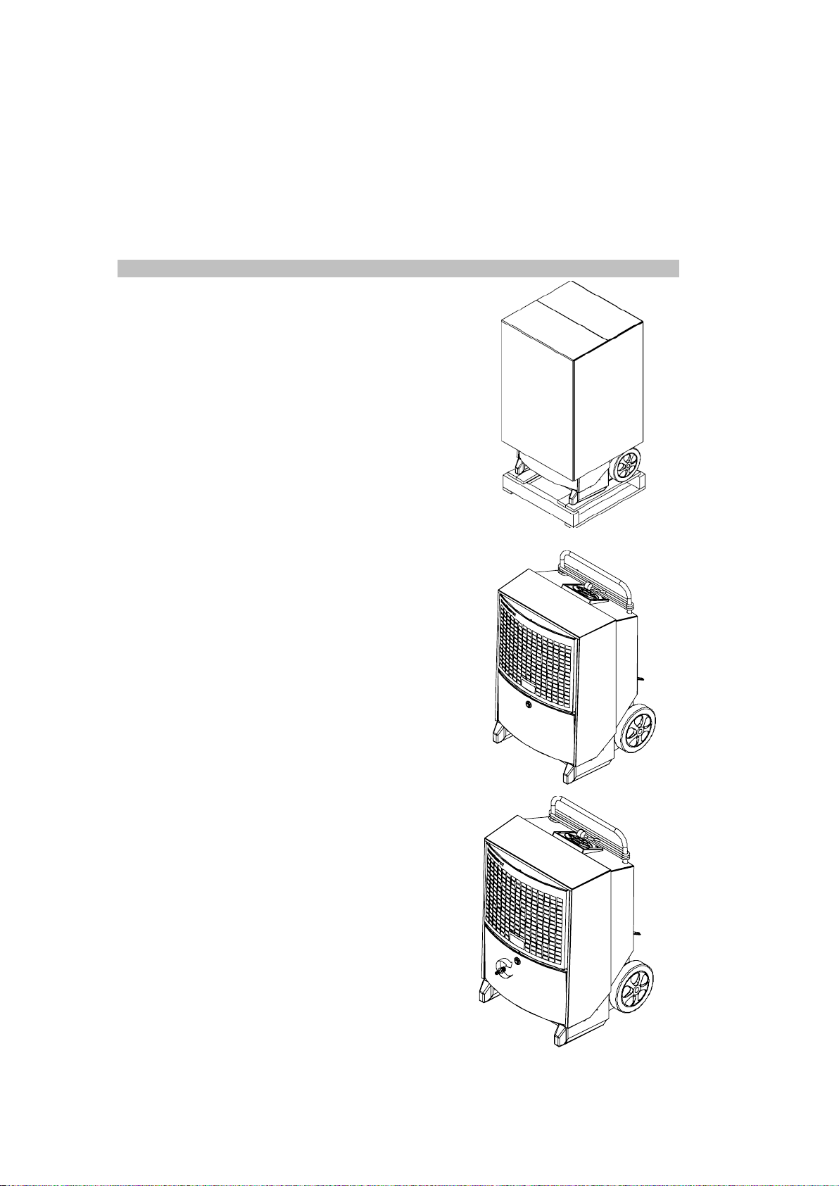
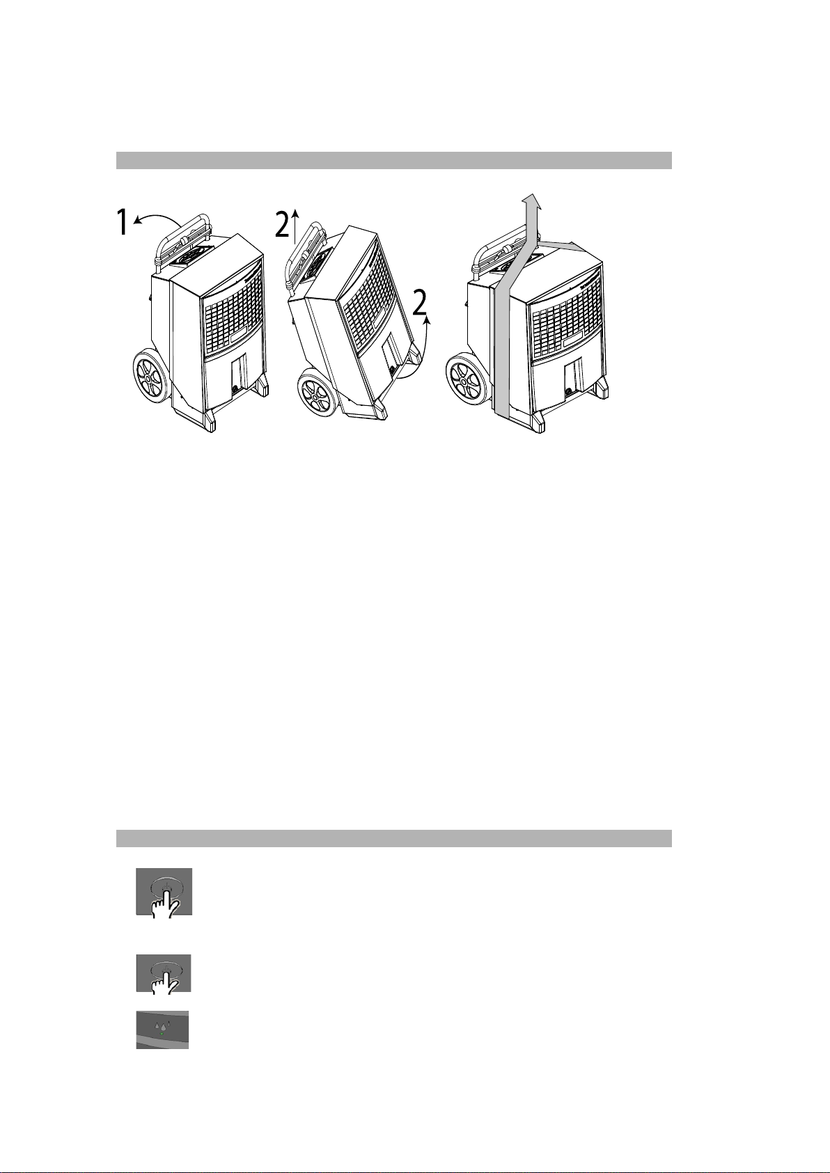
Set up and transport of the unit 6 - 8
Operating Manual 8 - 11
Accessories 12
Preventive maintenance 13 - 19
Fault finding and solving 20
Technical data 21
Measurements 22
Disposal 23 - 24
Wiring diagram 25
Spare parts 26
Exploded view KT 1130 27
1 of 27
Introduction
Topic

General Information
Introduction: This section gives the general information about this service manual and about the unit.
EC – Declaration of Conformity
EU-
Conformity
Declaration:
Dehumidifier, Type KT 1130
covered by this declaration, is in conformity with the following directives:
2006/42/EG Directive on the Safety of Machines
2014/30/EU EMC Directive
1907/2006/EU Reach Regulation
2011/65/EU RoHs-Guidline (electric- and electronic cold devices)
as well as in accordance with the following harmonized standards:
DS/EN ISO 12100:2010 Safety of machines
EN 60 335-1:2012 Safety of electrical appliances for use at home or similar purposes
EN 60 335-2-40:2003 Safety of electrical appliances for use at home or similar purposes
EN 60 335-2-40:A12006 Safety of electrical appliances for use at home or similar purposes
EN 378-1:2016 Refrigerating systems and heat pumps - Part 1
EN 378-2:2016 Refrigerating systems and heat pumps - Part 2
Moenchengladbach, 28.02.2021
Jochen Wilms
Place – Date Signature
Recycling: The unit is designed to last for many years. When the time comes for the unit to be recycled, the
unit should be recycled according to national rules and procedures to protect the environment.
2 of 27
Hans Wilms GmbH & Co. KG - Erftstr. 34 - 41238 Moenchengladbach – hereby declares that the
units mentioned below:
Managing Director

General warnings
Warning:
The dehumidifiers contain a flammable refrigerant. Take the following precautions,
to avoid any danger
Attention
•Please note that refrigerants may not have an odour.
Site requirements (installation and storage):
•The device must be installed, operated and stored in a room with a floor
area greater than 4 m². Check if there are any local regulations that you
have to observe when installing or storing the device.
•The device must be installed in a room without a permanently active ignition
source (for example: open fire, a gas device or electric air-heater in operation).
•Keep the ventilation openings free of foreign objects during operation.
Actions to be avoided (operation and handling)
•Be extra careful when handling the device so as not to cause damage
that can lead to a leak in the cooling circuit.
•Use to speed up the defrosting process or to clean
no other means recommended by the manufacturer.
•Do not drill or press with an open flame.
In case of fire:
•A fire can produce toxic fumes. In case of fire
therefore, you need to leave the room as soon as possible.
3 of 27

Product- and functional description
Introduction: This section will give you a description of the type KT 1130 and the functions:
Principles of The following describes the air flow
operation: through the dehumidifier:
The air flow through the
dehumidifier.
A fan draws in humid air through a
filter to the dehumidifier.
The air is cooled down and humidity/water
drops are led down to the water
tank.
The air is re-heated by e.g. the operation
of the dehumidifier (approx. increase in
temperature is +5°C/41°F).
Due to the repeated air circulation through the dehumidifiers, the air humidity is
continuously reduced whereby achieving rapid, but gentle drying.
The dehumidifier can operate continuously or it can be controlled by the built-in hygrostat.
Illustration: This illustration gives an overview of the dehumidifier:
Handle
Touchscreen
Supply air inlet with
PPI filter behind the
Power cable grill
Air Outlet Drain
Wheels Serial plate
Front View Rear View
Drain: The condensed water is collected in the integrated drip tray and then about a 1/2'-hose connection
is redirected to a drain.
The hose connection should be be mounted directly after unpacking.
to be continued on the next page
4 of 27

Product- and functional description, Continuation
Illustration: This illustrates the operator control:
Display/Operator
Control
Display
Function buttons
Status display
Main switch
Functions Main functions:
• Manual or automatic operation (built-in adjustable hygrostat)
• Socket for external hygrostat
• Display for temperature, relative humidity, hour meter and kW/h-consumption
• Hour meter and display for consumed kWh without 230V-connection
• Adjustable service interval counter
For correct operation look at the detailed instructions in this manual
Cooling Circuit
Diagram
Pos. Description Pos. Description
1 Compressor 6 Vaporizer
2 Condenser 7 Solenoid valve
3 Fan 8 Thermic expansion valve
4 Filter
5 of 27

Set up and transport of the unit
Introduction: This section provides information required for:
unwrapping the unit, making it ready for use and transportation of the unit.
Warning: If the dehumidifier has been laid down during transport, it is imperative to place it in
upright position for at least one hour before put into service!!!
Procedure: Follow these steps to unwrap the unit and make it ready for use:
Step Action Illustration
1 Unpack the dehumidifier.
Remove carton.
2 Remove dehumidifier from
pallet. The unit can now be
set up as described below.
3 Connect the drain sleeve.
4 Remove the protective film from the control panel
to be continued on the next page
6 of 27

Instructions for set up and transport of the unit, continuation
Placing Place the dehumidifier at a spot with good air circulation, where the minimum distance
from the air intake side should be 60 cm to the wall and from the air outlet side 3 m.
Location Since the appliances contain a flammable refrigerant, the following requirements for
requirements: the location must be fulfilled.
•The device must be installed, operated
and stored in a room with a area larger than
than 4 m².
Check whether there are any local regulations
that you have to obey when installing
or storing of the device.
•The device must be stored in a well-ventilated area, with the
room size must correspond to the room areas of 4 m².
•
The device must be installed in a room without permanently
active ignition sources (e.g. open fire, a gas appliance in operation or an
electric air heater in operation).
Optimal
Make sure that the room to be dehumidified is closed and the device is not
operation: placed near a heat source, such as e.g. a radiator.
Electrical The dehumidifier is complete with a 3,5 m cable and plug and ready for connection to a
Connection: 230 V / 50 Hz socket. Protect the socket with a 10 A fuse or a 16 A circuit breaker.
Stairs: The wheels are mounted so that the unit can easily be pulled upstairs without damaging
the housing or the stairs.
7 of 27

Transport/- The dehumidifier can be lifted by two persons or with a crane, see instructions below:
Replacing of Note: Observe local working environment rules regarding heavy lifting.
the dehumidifier:
2 People Hoist/Crane
Lift by lifting strap.
Operating Manual
Introduction All functions are controlled from the integrated touchscreen.
The operating instruction contains the following chapters:
Switching On-/Off and operating status 8 – 9
Displaytext 10 – 11
Textdisplay without main power 10
Exchange of the Data-memory battery 11
Fault reports 11
On-/Off- The following table shows the operation of the on-/off-function and the display texts
Switching and
operating status
Push button Display
ON – Continuous operation
INT HYG ON – Operation controlled by internal hygrostat
INT HYG STOP, if the preset value of the internal hygrostat is reached
EXT HYG ON – operation controlled by external hygrostat
EXT HYG STOP, if the preset value of the external hygrostat has
been reached
Switching off
The green LED shows active dehumidification.
to be continued on the next page
8 of 27

Operating Manual, Continuation
The following table shows the operation of the hygrostat function and the display texts
Operation of the
built-in hygrostat
Step Button Explanation
keep HYG SET Rhxxx% - flashes for 5 seconds. Dehumidifier changes then to
pressed the operation controlled by the internal hygrostat with preset value
(if the preset value has been reached the display shows: INT HYG STOP)
press Shortly press +/- in order to set the relative humidity value in the
(if it mentioned 5-second-time (lowest value 40 %). The new value will be
flashes) stored after another 5 seconds if the last button has been pushed
hold HYG SET RHxxx% - flashes for 5 seconds.
down The dehumidifier switches to continuous operation.
1 x press HYG Off will flashes. The setting is stored after 5 seconds.
(if it The dehumidifier then switches to the continuous operation.
flashes)
Operation of If an external hygrostat has been connected the unit automaticly changes to operation with this hygrostat.
an external
hygrostat Changes of the preset value can be done only on the external hygrostat.
(If the preset value has been reached the display shows: EXT HYG STOP)
Hour meter The built-in hour meter counts the total operating hours (can not be reset) as well as the hours until the
next service which can be changed. The service hour meter is switched off when the unit is delivered.
Step Button Explanation
SERVICE xxxxh – shows the hours until next authorised service.
keep pressed This value is automaticly stored after 5 seconds of flashing and the
function is activated if not already done. When the time for the service
intervall has been reached the display shows: SERVICE.
Shortly press +/- in order to preset a new service interval. The new value
will be stored 5 seconds after pressing of the last button
press
SET SERVICE OFF – pressing once more switches the servicetimer
1 x (if it function off
flashes)
to be continued on the next page
9 of 27

Operating Manual, Continuation
Display texts The following table shows how to operate the operating informations.
Button Explanation
XX°C – shows the ambient temperature
Actual RH% - shows the actual relative humidity
XX kWh – shows the total energy consumption. Cannot be reset.
xxxxh – shows the total of operating hours. Cannot be reset.
Text displays The dehumidifier has a built-in battery which makes it possible to read the display also
without if not connected to a power supply. Without main power the following can be read:
main power
Button Explanation
keep pressed
and
press once shows the total energy consumption in kW/h
keep pressed
and
press once shows the total operating hours of the dehumidifier
to be continued on the next page
10 of 27
c
c

Operating Manual, Continuation
Exchange of If the hour meter is separated from the power supply and can no longer be read then the cause is
the Data most probably an empty data store-battery.
store-battery Procedure how to exchange the battery:
Measure
1
2 Cut the cable strap which holds the battery. Exchange battery and use a new maximum
An overview of possible faults which make a normal operation impossible
Fault
informations Illustration Cause
Pressure or temperature
HIGH TEMP on display in the high-pressure dehumidifier for dirt in the
element too high airstream
Room temperature above
AMBIENT TEMP on display normal operating sector specified temperature
sector of 3°-32°C
SENSOR FAIL on display. 1: EVAP FAIL Call for authorized
One of the internal sensors is Thermo sensor of service technician
defective. evaporator defective
Use + / - buttons in order to
2: COND FAIL Call for authorized
change between 3 possible Thermo sensor of service technician
faults the condensor defective
3: ROOM FAIL Call for authorized
Built-in room temperature service technician
sensor defective
Leak in the cooling circuit Call for authorized
LP STOP on display service technician
11 of 27
Check filter and
Red light on right warning-LED
Place dehumidifier in
Red light on right warning-LED
SENSOR FAIL
Red light on right warning-LED
power supply
Loosen screws on both sides
of the touchscreen and lift
the touchscreen carefully.
2.5 mm wide cable strap.
Use only batteries of type Alkaline AAA.
Red light on right warning-LED
Warning: Before exchanging the battery make sure that the dehumidifier is disconnected from the
Ilustration of circuit board with battery in the wiring diagramm on page 25.
Fault information
Remmedy

Accessories:
Introduction Further information about each separate accessory is available on request to
Hans Wilms GmbH & Co. KG
List A list with illustration, description and part numbers of accessories for the KT 1130 follows:
Accessory Illustration Description KT-Type Part.-No.
Hygrostat Hygrostat with cable and jack plug KT 1130 3102004
12 of 27

Warnings Proper maintenance of the unit is necessary in order to achieve trouble-free operation.
Important! Always disconnect the power cable from the unit before doing any preventive
maintenance.
This product contains a flammable refrigerant. Before working on the system,
carry out security checks to reduce the risk of fire to a minimum.
•No open fire.
•No electrical ignition sources (open electrical contacts).
•No mechanical ignition sources (grinding processes).
•No combustible material near the workplace.
•Good ventilation of the area.
•Check the presence of refrigerants.
Other security measures
•Technicians and others working on site must be instructed in the nature
of the work to be carried out.
•The area around the workstation must be separated.
•Place a "No Smoking" - sign around the separation.
If hot work must be carried out on the refrigerant equipment or other related parts,
you have to have suitable fire extinguishing equipment at hand.
(Powder extinguisher A,B,C. CO2 extinguisher.)
Inspection The inspection checklist has been developed for operators for preventive maintenance.
by the No special skills are required for this service check. The checklist contains information:
operator:
•which components need to be inspected.
•
on the frequendy of inspection (Annual, Monthly, Weekly, Daily).
•how the inspection is to be carried out.
•criteria for acceptance or non-acceptance.
Annual Return the dehumidifier to an authorised service centre at the end of the service interval or
maintenance
or at least once a year.
or
The device is carefully maintained and inspected there, for leaks in the cooling system
maintenance
and tested for electrical safety.
according to Wilms also offers fixed service contacts where these devices can be repaired.
service For more details, please contact your nearest Wilms dealer.
interval
counter:
13 of 27
Preventive Maintenance

14 of 27
Checklist User

15 of 27
Checklist User

16 of 27
Checklist User

17 of 27
Checklist User

Monthly Please follow this procedure to carry out the monthly preventive maintenance:
Inspection:
Step
1 Open the front grill by tilting it
outwards.
2 Remove the filter, either rinse it with lukewarm
soapy water or vacuum-clean it if the filter
is only a little dirty.
Change the filter if it is very dirty.
See chapter Spare parts.
to be continued on the next page
18 of 27
Measure

Preventive Maintenance, Continuation
Step
Monthly 4 Remove the two screws on both sides
Inspection,
Continuation 1. Open the cover by approx. 5°
2. Lift the cover 1-2 cm until its loose from the housing
3. Pull the cover carefully over the hose nipple
6 Clean the evaporator coil by brushing with a
soft brush, a vacuum-cleaner or with compressed air.
3 Remove both TX20-screws on the front of the dripping bowl,
remove and clean the bowl.
TIP: When putting the dripping bowl back into place, make
sure that the rear edge of the dripping bowl is placed on
the edge insides of the dehumidifier.
4 Put cover back in place by running it through the hose connection
and then lift them over the upper edge of the housing.
19 of 27
Measure
During the monthly maintenance do NOT reset the service interval counter.
This manual suits for next models
1
Table of contents
Other WILMS Dehumidifier manuals
Popular Dehumidifier manuals by other brands

Koolbreeze
Koolbreeze DKB100L user manual

MSW Motor Technics
MSW Motor Technics MSW-DEH3190 user manual

Friedrich
Friedrich D25ANP Installation and operation manual

Amana
Amana R-AMAD501AW Use and care guide

Beko
Beko DRYPOINT RA VSD Series Instructions for installation and operation

TFT
TFT AD1100TE Technical manual