fisair DFLEX Series User manual

FISAIR S.L. C/Uranio, 20; PoI. Ind. Aimayr, 28330 San Martín de la Vega (Madrid) España.
Tel: (+34) 91 692 15 14 Fax: (+34) 91 691 64 56 | info@fisair.com| fisair.com
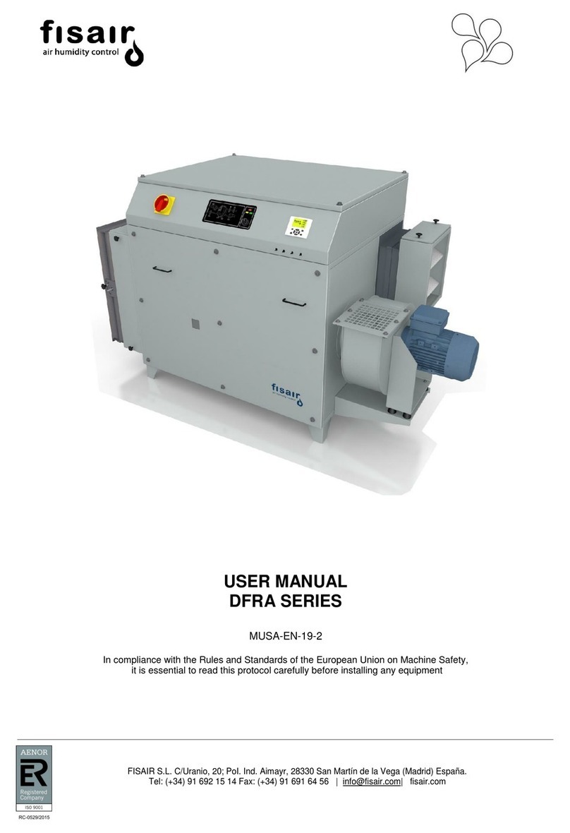
USER MANUAL
DFLEX SERIES
MUSX-EN-20-0
In compliance with the Rules and Standards of the European Union on Machine Safety,
it is essential to read this protocol carefully before installing any equipment

User Manual DFLEX Series |
2

User Manual DFLEX Series |
3
Contents
1. Introduction. ...........................................................................................4
2. Safety Instructions..................................................................................6
2.1 Spanish.........................................................................................................6
2.2 English ..........................................................................................................8
2.3 German.......................................................................................................10
2.4 French.........................................................................................................12
3. Transport and storage..........................................................................14
4. Operating principle. ..............................................................................15
5. Identification and coding of the model or equipment.............................16
5.1 Rating plates...............................................................................................18
6. Main components.................................................................................21
7. Operating Parameters..........................................................................22
8. Components technical data..................................................................23
8.1 Rotor...........................................................................................................23
9. Installation............................................................................................24
9.1 Location.......................................................................................................24
9.2 Service space..............................................................................................24
9.3 Air ducts......................................................................................................26
9.4 Connecting thermal fluids: steam reactivation battery..................................27
9.5 Connecting the gas supply to the gas reactivation heater............................29
9.6 Connecting thermal fluids: additional batteries.............................................31
9.7 Connection to the mains power supply........................................................34
9.8 Control and signalling connections..............................................................35
9.9 Flow adjustment..........................................................................................37
9.10 Differential pressure sensor:........................................................................38
9.11 Frequency inverter parameters:...................................................................40
10. Commissioning.....................................................................................41
11. Maintenance.........................................................................................44
11.1 Maintaining the dessicant rotor...................................................................45
11.2 Maintenance of air filters............................................................................46
12. Declaration of conformity......................................................................47
13. Guarantee............................................................................................48

User Manual DFLEX Series |
4
1. Introduction.
To ensure the correct operation of your DFLEX dehumidifier, please read this manual
carefully and keep it for future reference.
If there is any part of this document that you do not understand, or if you have any
questions about your dehumidifier, please contact us:
FISAIR, S.L.U.
Tel.: (+34) 91 692 15 14 –Madrid –SPAIN
Fax: (+34) 91 691 64 56 –Madrid –SPAIN
Email address www.info@fisair.com
Or contact your local distributor.
IMPORTANT!
The correctuse ofthe dehumidifier includesfollowing our instructions for installation, set-
up, operation and maintenance, as well as following the steps indicated in the
instructions in the correct sequence as described.
This dehumidifier may only be used by persons who are fully qualified and authorized to
do so.
Any person who transports and/or uses the unit or who works with it must read and
understand the relevant section of this manual, in particular the section entitled "Safety
Instructions".
You are advised to keep a copy of the user manual with the dehumidifier (or nearby).
Ignoring these instructions may invalidate all applicable guarantees and warranties.

User Manual DFLEX Series |
5
SPANISH:
FISAIR se exime de cualquier responsabilidad a menos que se cumplan con todas
las instrucciones de instalación y funcionamiento proporcionadas por FISAIR, o
si los productos han sido modificados o alterados sin el consentimiento por
escrito de FISAIR, o si tales productos han sido sometidos a un mal uso, mala
manipulación, alteración, mantenimiento inadecuado o muestran consecuencias
de accidente o utilización negligente. Estas situaciones pueden ser una conexión
de alimentación incorrecta, golpes con otros objetos, anulación de seguridades,
etc.
ENGLISH:
FISAIR disclaims all liability:
•unless all installation and operating instructions provided by FISAIR are
complied with
•if the products have been modified or altered without the written consent of
FISAIR
•if the products have been subjected to misuse, tampering, alteration, improper
maintenance or show consequences of accident or negligent use such as an
incorrect power connection, impacts from other objects, security override, etc.
GERMAN:
FISAIR lehnt jegliche Verantwortung ab, wenn nicht alle von FISAIR zur Verfügung
gestellten Montage- und Betriebsanleitungen eingehalten werden oder wenn die
Produkte ohne schriftliche Zustimmung von FISAIR modifiziert oder verändert
wurden oder wenn diese Produkte missbräuchlicher Verwendung,
unsachgemäßer Handhabung, Veränderung, unsachgemäßer Wartung ausgesetzt
waren oder Folgen von Unfall oder fahrlässiger Nutzung aufweisen. Dies kann
unter anderem eine falsche Stromverbindung, Schläge mit anderen Objekten, das
Entfernen von Sicherheits-/Schutzvorrichtungen usw. sein.
FRENCH:
FISAIR se dégage de toute responsabilité, sauf si toutes les consignes
d'installation et de fonctionnement fournies par FISAIR ont été respectées, si les
produits ont été modifiés ou altérés sans le consentement par écrit de FISAIR, ou
si ces produits ont été soumis à une mauvaise utilisation, une mauvaise
manipulation, une altération, une maintenance inadéquate ou s’ils montrent des
traces d'un accident ou d'une utilisation négligente. Ces situations peuvent être
une connexion d'alimentation incorrecte, de chocs avec d'autres objet,
d'annulation de sécurités, etc.

User Manual DFLEX Series |
6
2. Notas de seguridad/Safety Instructions/Sicherheitshinweise/Notes de
sécurité
2.1 Spanish
Lea con detenimiento estas notas de seguridad y examine el equipo a fin de
familiarizarse con él antes de instalarlo, ponerlo en marcha o realizar operaciones de
mantenimiento. Los siguientes símbolos o mensajes pueden aparecer en el presente
documento o en el equipo, advierten de posibles peligros o proporcionan información
que pueden ayudarle a aclarar o simplificar un procedimiento.
Atención, Tensión
La presencia de este símbolo en una etiqueta de peligro o de advertencia
indica que existe riesgo de electrocutarse, lo cual puede provocar lesiones
corporales o puede poner en peligro su vida sino se respetan las
instrucciones.
Atención
Este es el símbolo de una alerta de seguridad. Sirve para advertirle del
peligro potencial de sufrir lesiones corporales.
Respete todas las indicaciones de seguridad que acompañan a dicho
símbolo para evitar todasituación que pueda ocasionar lesiones y/o averías
en la unidad.
instalación de interruptor diferencial en la línea de alimentación eléctrica.
El instalador tiene la obligación de montar un interruptor diferencial
específico en la línea de alimentación eléctrica de la máquina.
Sobre el riesgo de incendio ante uso de materiales inadecuados
Existe el riesgo de incendio o explosión en el equipo ante la entrada de
materiales combustibles o inflamables en estado sólido, liquido o gaseo
(tanto en la entrada del aire de reactivación como la de proceso).
Ignorar estas instrucciones puede invalidar todas las garantías aplicables.

User Manual DFLEX Series |
7
En general
•Si nota que algo funciona mal o detecta fallos en el suministro de energía
eléctrica, apague la unidad inmediatamente y tome medidas para asegurarse de
que no se va a poner en marcha de nuevo. Los fallos deben ser corregidos
inmediatamente.
•Emplee personal debidamente cualificado para realizar los trabajos de
reparación, garantizando así el funcionamiento seguro de la unidad.
•Utilice únicamente piezas de recambio originales FISAIR.
•Consulte cualquier normativa local que restrinja o regule la utilización de este
deshumidificador.
Sobre el funcionamiento de la unidad
•No comprometa la seguridad de la unidad.
•Compruebe periódicamente los dispositivos de protección y aviso.
•El equipamiento de seguridad de la unidad no se debe eliminar o dejar fuera de
servicio.
Sobre los componentes eléctricos
•Los trabajos que afectan a componentes eléctricos deben ser llevados a cabo
por electricistas cualificados.
•Utilice únicamente fusibles de clase original y con la calibración correcta.
•Realice chequeos periódicos al equipo eléctrico.
•Los defectos, como conexiones flojas o cables quemados se deben reparar
inmediatamente.
Sobre la Instalación, Desmontaje, Mantenimiento y Reparación de la unidad
•La máquina no deberá ser manipulada cuando se encuentre en funcionamiento.
•Apague la alimentación de la unidad cuando serealicen tareas de mantenimiento
o reparaciones en la misma.
•No realice ampliaciones o instale equipamiento adicional en la unidad sin previa
aprobación por escrito de FISAIR.
El interruptor seccionador I1 debe de colocarse
en posición “0” y boqueado mediante un candado
para acceder al plenum del ventilador y/o realizar
cualquier acción de mantenimiento a bordo de
la unidad.
De igual modo, en equipos dotados de calentador de gas o vapor
para labores de mantenimiento se debe consignar la válvula de
alimentación de gas combustible o vapor mediante un dispositivo
loto de suministro opcional.
Parada en situación de emergencia para evacuar calor residual
El equipo no dispone de parada de emergencia general en el cuadro de mandos
para evitar un posible accidente por la no evacuación del calor residual en el flujo
de reactivación. Para llevar a cabo la parada frente a una situación de inminente
riesgo o accidente, utilice el interruptor seccionador I1 identificado en rojo y
amarillo y póngalo en posición 0.
No se debe realizar para hacer la parada funcional del equipo en un uso normal.

User Manual DFLEX Series |
8
2.2 English
Read these safety notes carefully and examine your equipment to familiarize yourself
with it before installing, commissioning, or performing maintenance operations.
The following symbols or messages, which may appear in this document or on your
computer, warn of potential hazards, or provide information that can help you clarify or
simplify a procedure.
Attention
The presence of this symbol on a hazard or warning label indicates that there
is a risk of electrocution, which may result in life threatening injury or death if
the instructions are not respected.
Attention
This is the symbol of a security alert. It serves to warn you of the potential
danger of bodily injury. Observe all safety instructions that accompany this
symbol to avoid any situation that may cause injury and/or damage to the unit.
Fused Isolator installation and the power supply line.
The installer is required to mount a specific fused isolator on the machine's
power supply.
Fire risk from the use of inappropriate materials
There is a risk of fire or explosion if any combustible or flammable
materials in solid, liquid or gaseous state enter the equipment (at the inlet
of the reactivation air or the process air). Ignoring these instructions will
invalidate all applicable warranties.

User Manual DFLEX Series |
9
General
•If you notice a malfunction or detect power failure, turn the unit off immediately and
ensure it cannot start up again.
•Problems must be fixed immediately.
•Use properly qualified personnel to carry out repair work, thus ensuring the safe
operation of the unit.
•Use only original FISAIR spare parts.
•Refer to any local regulations that restrict or regulate the use of this dehumidifier.
Operation of the unit
•Do not compromise the safety of the unit.
•Periodically check the protection and warning devices.
•The safety equipment of the unit must not be removed or left out of service.
Electrical components
•Work affecting electrical components must be carried out by qualified electricians.
•Use only original class fuses with correct calibration.
•Perform regular checkups on the electrical equipment.
•Defects, such as loose connections or burnt cables, should be repaired immediately.
Installation, Disassembly, Maintenance and Repair of the Unit
•The machine must not be tampered with when in operation.
•Turn off power to the unit when maintenance or repairs are being performed.
•Do not upgrade or install additional equipment on the unit without prior written approval
from FISAIR.
The I1 isolator switch must be placed in the "0"
position and locked out with a padlock to access
the fan plenum and/or perform any maintenance
action within the unit.
Similarly, the fuel, gas or steam feed valves
be locked out in gas or steam equipment by means of a suitable
mechanical valve lockout, for maintenance.
Emergency stop to evacuate waste heat
The equipment does not have a general emergency stop on the control panel.
This is to avoid a possible accident due to not removing waste heat in the
reactivation flow. To stop in a situation of imminent risk or accident, use the I1
isolator identified in red and yellow and set it to position 0.
This should not be used to for a normal stop of the equipment.

User Manual DFLEX Series |
10
2.3 German
Lesen Sie diese Sicherheitshinweise aufmerksam durch und prüfen Sie das Gerät, bevor
Sie es installieren, in Betrieb nehmen oder Wartungsarbeiten durchführen.
Die folgenden Symbole oder Meldungen können in diesem Dokument oder auf dem
Gerät erscheinen, vor möglichen Gefahren warnen oder Informationen bereitstellen, die
zur Klärung oder Vereinfachung des Verfahrens beitragen können.
Vorsicht, Spannung
Das Vorhandensein dieses Symbols auf einem Gefahren- oder Warnschild
weist auf das Risiko eines Stromschlags hin, der zu Körperverletzungen
oder zu lebensgefährlichen Situationenführen kann, wenn die Anweisungen
nicht befolgt werden.
Achtung
Dies ist das Symbol eines Sicherheitsalarms. Das Symbol warnt Sie vor
möglichen Verletzungsgefahren.
Beachten Sie alle Sicherheitshinweise zu diesem Symbol, um Situationen
zu vermeiden, die Verletzungen und/oder Schäden am Gerät verursachen
können.
Installation eines Differenzialschalters an der Stromversorgungsleitung.
Der Installateur ist verpflichtet, einen speziellen Differenzialschalter an der
Stromversorgungsleitung des Geräts anzubringen.
Brandgefahr bei Verwendung ungeeigneter Materialien
Es besteht Brand- oder Explosionsgefahr im Gerät, wenn brennbare oder
entflammbare Stoffe in festem, flüssigem oder gasförmigem Zustand (im
Einlass von Reaktivierungsluft und Prozessluft) eintreten.
Durch die Nichteinhaltung dieser Anweisungen können alle geltenden
Garantien ihre Gültigkeit verlieren.
Allgemeines
•Wenn Sie eine Fehlfunktion oder einen Stromausfall feststellen, schalten Sie das
Gerät sofort aus und ergreifen Sie Maßnahmen, um sicherzustellen, dass es
nicht wieder eingeschaltet wird. Fehler sind sofort zu beheben.
•Verwenden Sie nur Original-FISAIR-Ersatzteile.
(Lieferung von Leitung und Schutz-/Sicherheitsvorrichtung durch andere/Protection electric
supply by others)
Stromversorgung/supply: entsprechend dem Typenschild des Geräts/according to rating plate
P[kW]= entsprechend dem Typenschild des Geräts/according to rating plate
l[A]- entsprechend dem Typenschild des Geräts/according to rating plate

User Manual DFLEX Series |
11
•Um einen sicheren Betrieb des Geräts zu gewährleisten, dürfen
Reparaturarbeiten nur von entsprechend qualifiziertem Personal durchgeführt
werden.
•Beachten Sie lokale Vorschriften, die den Einsatz dieses Luftentfeuchters regeln
bzw. einschränken.
Über den Betrieb des Geräts
•Tun Sie nichts, was die Sicherheit des Geräts gefährdet.
•Überprüfen Sie regelmäßig die Schutz- und Warnvorrichtungen.
•Die Sicherheitseinrichtung des Geräts darf nicht entfernt oder außer Betrieb
genommen werden.
Über die elektrischen Komponenten
•Arbeiten an elektrischen Komponenten dürfen nur von Elektrofachkräften
ausgeführt werden.
•Verwenden Sie nur korrekt kalibrierte Sicherungen der ursprünglichen Klasse.
•Führen Sie regelmäßige Kontrollen an den elektrischen Geräten durch.
•Defekte wie lose Verbindungen oder verbrannte Drähte müssen sofort repariert
werden.
Installation, Demontage, Wartung und Reparatur des Geräts
•Während des Betriebs darf nicht an dem Gerät herumhantiert werden.
•Schalten Sie das Gerät aus, wenn Wartungsarbeiten oder Reparaturen am Gerät
durchgeführt werden müssen.
•Nehmen Sie keine Erweiterungen vor und installieren Sie keine zusätzlichen
Geräte ohne vorherige schriftliche Genehmigung von FISAIR.
Der Trennschalter I1 muss auf Position „0“
gestellt und mit einem Vorhängeschloss
verriegelt werden, das den Zugang zum Plenum
des Gebläses und/oder für jegliche Art von
Wartungsarbeiten an dem Gerät absichert.
Gleichermaßen muss bei Gas- oder Dampfanlagen für
Wartungsarbeiten das Gas- oder Dampfzufuhrventil) mit einer
Wartungssicherung (LOTO) versehen werden, die optional
mitgeliefert werden kann.
Notstopp zur Ableitung der Abwärme
Das Gerät verfügt nicht über eine allgemeine Notabschaltung auf der Schalttafel,
um einen möglichen Unfall aufgrund einer Nichtableitung der Abwärme im
Reaktivierungsstrom zu vermeiden. Für eine Abschaltung des Geräts im Falle
einer unmittelbaren Gefahr oder eines Unfalls stellen Sie den rotgelben
Trennschalter I1 auf Position 0. Eine solche Abschaltung darf nicht durchgeführt
werden, um das Gerät bei Normalbetrieb abzuschalten.

User Manual DFLEX Series |
12
2.4 French
Veuillez lire attentivement ces notes de sécurité et bien examiner l’appareil afin de vous
familiariser avec lui avant son installation, sa mise en marche et les opérations de
maintenance.
Les symboles ou messages suivants peuvent apparaître dans le présent document ou
sur la machine, pour prévenir de dangers éventuels ou apporter des informations
susceptibles de vous aider à mieux comprendre ou à simplifier une procédure.
Attention, Tension
La présence de ce symbole sur une étiquette de danger ou d’avertissement
indique l’existence d’un risque d’électrocution, ce qui peut provoquer des
blessures corporelles ou mettre en danger votre vie si les instructions ne
sont pas respectées.
Attention
C’est le symbole d’une alerte de sécurité. Il vise à vous prévenir d’un danger
potentiel de blessures corporelles.
Veuillez respecter toutes les indications de sécurité qui accompagnent ce
symbole pour éviter toute situation pouvant entraîner des blessures et/ou
des pannes de la machine.
Installation d’un interrupteur différentiel sur la ligne d’alimentation électrique.
L’installateur a l’obligation de monter un interrupteur différentiel spécifique
sur la ligne d’alimentation électrique de la machine.
Concernant le risque d’incendie dû à l’utilisation de matériel inadéquat
Il existe un risque d’incendie ou d’explosion sur la machine en cas d’entrée
de matériaux combustibles ou inflammables à l’état solide, liquide ou gazeux
(au niveau de l’entrée de l’air de réactivation et de l’entrée de processus).
Le manquement à ces consignes peut invalider toutes les garanties en
vigueur.
En général
•Si vous remarquez que quelque chose fonctionne mal ou si vous détectez des
pannes au niveau de l’alimentation en énergie électrique, éteignez
immédiatement la machine et prenez des mesures pour vous assurer que la
machine ne va pas être remise en marche. Les pannes doivent être
immédiatement corrigées.
(Ligne et protection par d’autres/Protection electric supply by others)
Alimentation/supply: suivant la plaque caractéristique de la machine/according to rating plate
P[kW] = suivant la plaque caractéristique de la machine/according to rating plate
l[A]- suivant la plaque caractéristique de la machine/according to rating plate

User Manual DFLEX Series |
13
•Utilisez uniquement des pièces de rechange originales FISAIR.
•Faites appel à du personnel dûment qualifié pour effectuer les travaux de
réparation, pour garantir ainsi le fonctionnement sécurisé de la machine.
•Consultez la réglementation locale qui restreint ou régule l’utilisation de ce
déshumidificateur.
Concernant le fonctionnement de la machine
•Veillez à la sécurité de la machine.
•Vérifiez régulièrement les dispositifs de protection et d’alerte.
•L’équipement de sécurité de la machine ne doit pas être éliminé ou mis hors
service.
Concernant les composants électriques
•Les travaux qui affectent les composants électriques doivent être effectués par
des électriciens qualifiés.
•Utilisez uniquement des fusibles de classe originale et de bon calibre.
•Révisez régulièrement l’équipement électrique.
•Les défauts, tels que les connexions distendues ou les câbles brûlés, doivent
être réparés immédiatement.
Concernant l’installation, le démontage, la maintenance et la réparation de la
machine
•La machine ne devra pas être manipulée lorsqu’elle fonctionne.
•Éteignez l’alimentation de la machine pendant les travaux de maintenance ou de
réparation.
•N’effectuez pas d’agrandissement et n’installez pas d’équipement
supplémentaire sur la machine sans l’accord préalable écrit de FISAIR.
L’interrupteur sectionneur I1 doit être placé sur la
position « 0 » et bloqué avec un cadenas pour
accéder au plenum du ventilateur et/ou réaliser
n’importe quelle action de maintenance sur la
machine.
De même, sur leséquipements à gazou à vapeur pour les travaux
de maintenance, il faut consigner le robinet d’alimentation en gaz
combustible ou en vapeur à l’aide d’un dispositif loto fourni en
option.
Arrêt en situation d’urgence pour évacuer la chaleur résiduelle
L’équipement ne dispose pas d’arrêt d’urgence général sur le tableau de
commandes afin d’éviter tout accident dû à la non-évacuation de la chaleur
résiduelle dans le flux de réactivation. Pour arrêterla machine en cas de situation
de danger ou d’accident imminent, utilisez l’interrupteur sectionneur I1 marqué
en rouge et jaune et mettez-le sur la position 0.
Cette manœuvre ne doit pas servir à l’arrêt fonctionnel de la machine lors d’une
utilisation normale.

User Manual DFLEX Series |
14
3. Transport and storage.
When in transit, the unit must be protected from impacts of any kind, and all possible
measures must be taken to prevent malfunctions due to improper loading or unloading
of the unit.
When lifting the equipment, always use a pallet truck or forklift.
Keep the unit dry and protected from the elements while in storage.
The unit must be stored in a location where the ambient temperature is between -20ºC
and 60ºC and with a relative humidity of no more than 80%.

User Manual DFLEX Series |
15
4. Operating principle.
The FISAIR DFLEX series air dehumidifiers operate using a substance (silica gel) which
adsorbs moisture from the air and is configured as a cylinder with many small channels
of this material all running in the same direction as the air flow.
The front surface of the base of this cylinder is divided into two zones: one is intended to
carry out the drying process, and the other to regenerate or reactivate the desiccant. The
large surface contact area of air to desiccant material within this configuration enables
an effective drying process to be achieved with a minimum volume of material.
The dry/process air circuit occupies 75% (270°) of the surface area of the desiccant rotor
in the FISAIR DFRA series dehumidifiers, where the material adsorbs water vapour from
the air passing through it. The reactivation air circuit is heated by a heating component
and passes through the rotor in the opposite direction to the process air. This removes
moisture from the desiccant material; thus regenerating it for a new cycle.
A rotor motor (low power gearmotor with a V-belt drive on the perimeter) ensures the
drying process is continuous and uniform.
The system design is completed with a set of seals separating the two air circuits and
seals around the perimeter of the rotor; thus ensuring separation between air flows.
Figure 1: Operating principle of drying by adsorption rotor.
Calentador de
reactivación
Aire
seco
Aire de
reactivación
Sector de
reactivación
Aire
mojado
Rotor
desecante
Aire de
proceso
Reactivation
sector
Reactivation
heater
Reactivation air
Dry air
Moist air
Process air
Desiccant rotor

CODING
PRODUCT
DFRA / DFLEX
SERIES DFRA- DFLEX
MODEL
REACTIVATION SYSTEM
E= Electric coil
A
=Coil for hot water
S
=Hot Water coil + electric coil
V= Coil for saturated steam
H=
Stainless steel coil for saturated steam
D= Saturated steam coil + electric coil
X= Stainless steel coil for saturated steam+ electric coil
G= Direct Gas
PROCESS AIR FILTERS
00 = Without filters
G0 = 1 Filters stage class G4 (EN779:2012)
GF = First stage class G4 filters and second stage class F9 (EN779:2012)
C0 = 1 stage of filters of a specific class other than G4 (EN779:2012)
0F = 1 Filters stage class F9 (EN779:2012)
CC = Two stages of filtering other than G4F9(EN779:2012)
REACTIVATION AIR FILTERS
00 = Without filters
G0 =1 Filter stage class G4 (EN779:2012)
GF = First stage class G4 filters and second stage class F9 (EN779:2012)
C0 = 1 stage of filters of a specific class other than G4 (EN779:2012)
0F =1 Filter stage class F9 (EN779:2012)
CC = Two stages of filtering other than G4F9(EN779:2012)
PRE-HEATING
00 =
No pre-heating
WE = ECO pre-heating coils for hot water.
WS =
STANDARD pre-heating coil for hot water.
WH = Water High Power Heating Coil
CW = Custom pre-heating coil
PRE-COOLING
00 =
No pre-cooling
WE = ECO pre-heating coil for cold water.
WS = STANDARD pre-cooling coil for cold water.
WH = High-power pre-cooling coil for cold water.
DS =
STANDARD pre-cooling coil for direct expansion.
CW = Custom pre-cooling coil
POST-COOLING
00 = No post-cooling
WE = ECO post-cooling coil for cold water.
WS = STANDARD post-cooling coil for cold water.
WH = High-power post-cooling coil for cold water.
DS =STANDARD post-cooling coil for direct expansion.
CW =
Custom Post-cooling coil
POST-HEATING
00 = No post-heating
WE = ECO post-heating coil using hot water.
WS = STANDARD post-heating coil using hot water.
WH = Water High power heating Coil
CW = Custom Post-Heating coil
PROCESS AIR / DRY AIR FAN
00 = No process/dry air fan
SF = STANDARD fan
PF = POWERED fan
PS =Plug-Fan for DFRA serie
PP =Multiple Plug-Fan (Wall-Fan)
PT = Multipl Plug Fan (Tandem Plug-Fan)
REACTIVATION AIR / MOIST AIR FAN
SF = STANDARD fan
PF = POWERED fan
DRY AIR FILTER
000 = Without final filter at dry air.
F00 = Class F9 EN 779: 2012 /ePM1 80< ISO16890. Filter fitted after the process air/dry air fan (requires a Plug-Fan ventilator)
H13 = HEPA H13 (EN 1822:2011) filter fitted after the process air/dry air fan (requires a Plug-Fan ventilator)
H14 = HEPA H14 (EN 1822:2011) filter fitted after the process air/dry air fan (requires a Plug-Fan ventilator)
FH3 = Class F9 EN 779: 2012 /ePM1 80< ISO16890 + HEPA H13 (EN 1822:2011). Filter fitted after the process air/dry air fan (requires a Plug-Fan ventilator)
FH4 = Class F9 EN 779: 2012 /ePM1 80< ISO16890 + HEPA H14 (EN 1822:2011). Filter fitted after the process air/dry air fan (requires a Plug-Fan ventilator)
SENSITIVE HEAT RECOVERY UNIT
0=
Without heat recuperator. No by-pass in desiccant rotor.
R= Static heat recuperator installed in the discharge of wet air.
D= By-pass air damper in descending rotor.
M= Static heat recuperator installed in the discharge of wet air. By-pass air damper in descending rotor.
FINISHING
00 = Standard production of components. Protection grade IP50 and finished with RAL7035 colour.
0R = Standard production of components. Protection grade IP50 and finished with specific colour (RAL____).
K0 = Standard production of components. Protection grade IP54 and finished with RAL7035 colour.
KR = Standard production of components. Protection grade IP54 and finished with specific colour (RAL____).
REACTIV. SYST.
PROCESS AIR
INITIAL FILTER
REACTV. AIR
INITIAL FILTER
PRE-COILS
POST-COILS
405
AE04
0
FANS
DRY AIR FINAL
FILTER
HEAT
RECOVERY
FINISHING
ELECTRICAL
POWER
SUPPLY
SF
SF
E
GF
H14
R
KR
GF
WS
WS
WS
WS
0100
1100
0130
1300
0160
1700
0175
2100
0200
2900
0230
3500
0300
0400
0500
0650
0900
Rev01 28-02-19
CONTROL
OTHER
SPECIAL
DFRA-0900

CODING
PRODUCT
DFRA / DFLEX
POWER SUPPLY OPTIONS (NOT INCLUDED IN MECHANICAL DRAWINGS)
405
=
Standard electrical power supply at 400V ±5% /III/50Hz
N05 =Electrical power supply at 400V ±5% /III/50Hz
406
=
Electrical power supply at 400V ±5% /III/60Hz
N06 = Electrical power supply at 400V±5%/III+N/60Hz
445
=
Electrical power supply at 440V ±5% /III/50Hz
N45 = Electrical power supply at 440V±5%/III+N/50Hz
446
=
Electrical power supply at 440V ±5% /III/60Hz
N46 = Electrical power supply at 440V±5%/III+N/60Hz
466
=
Electrical power supply at 460V ±5% /III/60Hz
N66 = Electrical power supply at 460V±5%/III+N/60Hz
235
=
Electrical power supply at 230V ±5% /III/50Hz
236
=
Electrical power supply at 230V ±5% /III/60Hz
CONTROL OPTIONS (NOT INCLUDED IN MECHANICAL DRAWINGS)
BE00
= Basic ON/OFF control with electric heater for reactivation.
BV00
=
Basic ON/OFF control with saturated steam heater for reactivation.
AE13
= Advanced electrical reactivation control and one actuator. (Electrical . 0..10V)
AE27
=
Advanced electrical reactivation control and two actuators. (Electrical . 0..10V)
AE49
= Advanced electrical reactivation control and four actuators. (Electrical . 0..10V)
AE57
Advanced electrical reactivation control and five actuators. (Electrical . 0..10V)
AE79 Advanced electrical reactivation control and sevent actuators. (Electrical . 0..10V)
CE27
= Advanced electrical reactivation control and two actuators. (Electrical . (0..10V)+Profibus Gateway
CE49
= Advanced electrical reactivation control and four actuators. (Electrical . (0..10V)+Profibus Gateway
CE57
Advanced electrical reactivation control and five actuators. (Electrical . (0..10V)+Profibus Gateway
CE79 Advanced electrical reactivation control and sevent actuators. (Electrical . (0..10V)+Profibus Gateway
AV03
= Steam reactivation advanced control.
AV17
= Advanced steam reactivation control and one actuator. (Electrical . 0..10V)
AV39
= Advanced steam reactivation control and three actuators. (Electrical . 0..10V)
AV47 Advanced steam reactivation control and four actuators. (Electrical . 0..10V)
AV69 Advanced steam reactivation control and six actuators. (Electrical . 0..10V)
CV17
= Advanced steam reactivation control and one actuator (Electrical 0..10V) + Profibus Gateway.
CV39
= Advanced steam reactivation control and three actuators. (Electrical . (0..10V)+Profibus Gateway
CV47
Advanced steam reactivation control and four actuators. (Electrical . (0..10V)+Profibus Gateway
CV69 Advanced steam reactivation control and six actuators. (Electrical . (0..10V)+Profibus Gateway
AG03
= Gas reactivation advanced control.
AG17
= Advanced gas reactivation control and one actuator. (Electrical . 0..10V)
AG39
= Advanced gas reactivation control and three actuators. (Electrical . 0..10V)
AG47 Advanced gas reactivation control and four actuators. (Electrical . 0..10V)
AG69 Advanced gas reactivation control and six actuators. (Electrical . 0..10V)
CG17
= Advanced gas reactivation control and one actuator (Electrical 0..10V) + Profibus Gateway.
CG39
= Advanced gas reactivation control and three actuators. (Electrical . (0..10V)+Profibus Gateway
CG47 Advanced gas reactivation control and four actuators. (Electrical . (0..10V)+Profibus Gateway
CG69 Advanced gas reactivation control and six actuators. (Electrical . (0..10V)+Profibus Gateway
OTHER SPECIAL OPTIONS
C = Accessories that can be built-in subject to specification and preliminary study.
Example:
DFRA-0500V GFGF 00WS WE00 SFSF 000 R00 405BV000
CONTROL
OTHER
SPECIAL
FANS
DRY AIR FINAL
FILTER
HEAT
RECOVERY
FINISHING
ELECTRICAL
POWER
SUPPLY
REACTIV. SYST.
PROCESS AIR
INITIAL FILTER
REACTV. AIR
INITIAL FILTER
PRE-COILS
POST-COILS

User Manual DFLEX Series |
18
5.1 Rating plates
The rating plates provide essential information about the technical features of the
machine.
The EC Machinery Safety Regulation requires all machinery operated within the
European Economic Community to have a rating plate indicating it’s main features, the
machine serial number and the manufacturer's name displayed in a durable manner.
The DFLEX series has two types of plates:
•The larger main plate is located on the outside of the electrical panel housing for
the basic unit, near the circuit breaker. It states:
-Equipment model
-Serial number
-Electrical power connection
-Nominal power for the equipment
-Nominal current for the equipment.
-Reactivation heater type and power.
-Reactivation heater maximum pressure (if applicable).
-Pre-cooling battery BF1 fluid and temperature (if applicable).
-Pre-cooling battery BF1 maximum pressure (if applicable).
-Pre-heating battery BC1 fluid and temperature (if applicable).
-Pre-heating battery BC1 maximum pressure (if applicable).
-Post-cooling battery BF2 fluid and temperature (if applicable).
-Post-cooling battery BF2 maximum pressure (if applicable).
-Post-heating battery BC2 fluid and temperature (if applicable).
-Post-heating battery BC2 maximum pressure (if applicable).
-Heat recovery maximum power (if applicable).
-Dry air fan motor, maximum power and current.
-Reactivation fan motor, maximum power and current.
-Place and date of manufacture.
-Machine type.
-According to which directive is designed.
-To which FISAIR machines can be join (if applicable).

User Manual DFLEX Series |
19
•The smaller plate is inside the electrical panel and contains the most relevant
electrical information:
-Equipment model
-Serial number
-Electrical power connection
-Nominal power for the equipment
-Nominal current for the equipment.
-Electrical wiring number
-Name of the PLR configuration program (Programmable Logic Relay)
-Place and date of manufacture
Figure 2: Example of a DFLEX series ratings plate

User Manual DFLEX Series |
20
Figure 3: DFLEX series machine ratings plate location
on control panel (visible from the outside)
Figure 4: DFLEX series electric panel ratings plate location
(on control panel after opening, on the reverse side)
Other manuals for DFLEX Series
2
This manual suits for next models
6
Table of contents
Other fisair Dehumidifier manuals

fisair
fisair DFRB-060-E Installation guide

fisair
fisair DFLEX Series Use and maintenance manual

fisair
fisair DFRA Series Use and maintenance manual

fisair
fisair DFRA Series User manual

fisair
fisair DFRA Series User manual

fisair
fisair DFRIGO Series User manual

fisair
fisair DFLEX Series User manual

fisair
fisair DFRA Series Use and maintenance manual