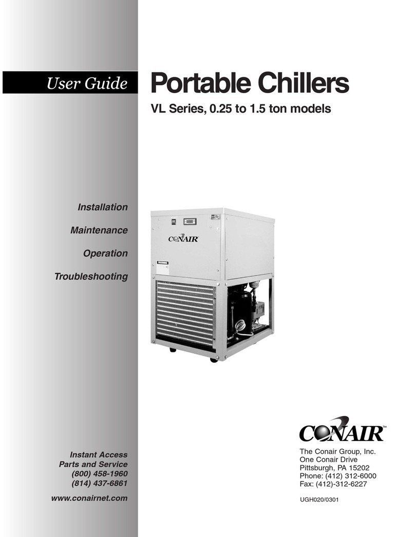
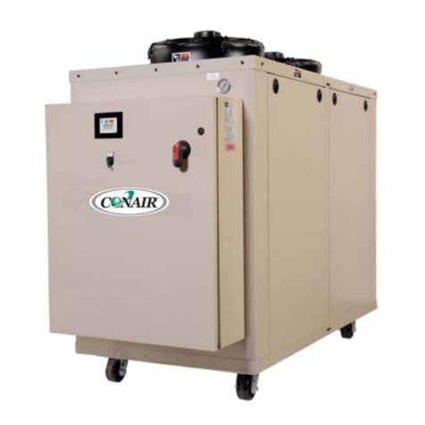
Conair PCW-1.5 User manual

Portable Chillers
Water-cooled models PCW-1.5 to PCW-30
and Air-cooled models PCA1.5 to PCA-30
Corporate Office: 412.312.6000 lInstant Access 24/7 (Parts and Service): 800.458.1960 l Parts and Service: 814.437.6861
USER GUIDE
UGH024-0907
www.conairnet.com
INTRODUCTION • Purpose of the User Guide • How the guide is organized •Your responsibilities as a user •ATTENTION:
Read this so no one gets hurt • DESCRIPTION • What is the Portable Chiller? • Typical applications • Limitations
•How it works • Specifications: Portable Chillers • INSTALLATION • Unpacking the boxes • Warnings and cautions •
Preparing for installation • Making process plumbing connections • Filling the chiller • Checking the refrigerant charge
• Connecting the main power source • Checking electrical connections • Checking pump rotations • Checking the com-
pressor • Checking the sight glass • Initially warming the chiller • Checking for leaks •Initially running the chiller •
Stopping the chiller • OPERATION • TIC control features • PLC control features • Before starting • Starting/stopping
the chiller • Changing settings • Changing the setpoint temperature • Menu features • Tuning the chiller • Powering up
• Running/stopping the chiller • Viewing chiller status screens • Programming settings • Changing setpoint •

Please record your equipment’s
model and serial number(s) and
the date you received it in the
spaces provided.
It’s a good idea to record the model and serial number(s) of your equipment and
the date you received it in the User Guide. Our service department uses this infor-
mation, along with the manual number, to provide help for the specific equipment
you installed.
Please keep this User Guide and all manuals, engineering prints and parts lists
together for documentation of your equipment.
Date:
Manual Number: UGH024-0907
Serial Number(s):
Model Number(s):
DISCLAIMER: The Conair Group, Inc., shall not be liable for errors contained in this User Guide or
for incidental, consequential damages in connection with the furnishing, performance or use of
this information. Conair makes no warranty of any kind with regard to this information, including,
but not limited to the implied warranties of merchantability and fitness for a particular purpose.
Copyright 2007 l The Conair Group l All rights reserved

Table of Contents
1-1 Introduction
Purpose of the user guide. . . . . . . . . . . . . . . . . . . . . . . . . . . . . . . . 1-2
How the guide is organized . . . . . . . . . . . . . . . . . . . . . . . . . . . . . . 1-2
Your responsibilities as a user. . . . . . . . . . . . . . . . . . . . . . . . . . . . . 1-3
ATTENTION: Read this so no one gets hurt . . . . . . . . . . . . . . . . . . . 1-4
2-1 Description
What is the Portable Chiller? . . . . . . . . . . . . . . . . . . . . . . . . . . . . . .2-2
Typical applications . . . . . . . . . . . . . . . . . . . . . . . . . . . . . . . . . . . . .2-3
Limitations . . . . . . . . . . . . . . . . . . . . . . . . . . . . . . . . . . . . . . . . . . . 2-3
How it works:Water-cooled Portable Chillers. . . . . . . . . . . . . . . . . .2-4
How it works: Air-cooled Portable Chillers. . . . . . . . . . . . . . . . . . . . 2-6
Portable Chiller features . . . . . . . . . . . . . . . . . . . . . . . . . . . . . . . . . 2-8
Pump curves. . . . . . . . . . . . . . . . . . . . . . . . . . . . . . . . . . . . . . . . . 2-10
3-1 Installation
Unpacking the boxes . . . . . . . . . . . . . . . . . . . . . . . . . . . . . . . . . . . 3-2
Warnings and cautions . . . . . . . . . . . . . . . . . . . . . . . . . . . . . . . . . . 3-3
Preparing for installation. . . . . . . . . . . . . . . . . . . . . . . . . . . . . . . . . 3-4
Making process plumbing connections . . . . . . . . . . . . . . . . . . . . . . 3-5
Filling the Chiller. . . . . . . . . . . . . . . . . . . . . . . . . . . . . . . . . . . . . . . 3-8
Checking refrigerant charge . . . . . . . . . . . . . . . . . . . . . . . . . . . . . 3-10
Connecting the main power source. . . . . . . . . . . . . . . . . . . . . . . . 3-11
Checking electrical connections . . . . . . . . . . . . . . . . . . . . . . . . . . 3-12
TIC CONTROL
Checking pump rotation . . . . . . . . . . . . . . . . . . . . . . . . . . . . . . . . 3-13
Table of Contents l i

Checking the compressor . . . . . . . . . . . . . . . . . . . . . . . . . . . . . . . 3-13
Checking the water level gauge . . . . . . . . . . . . . . . . . . . . . . . . . . 3-13
PLC CONTROL
Initially warming the Chiller. . . . . . . . . . . . . . . . . . . . . . . . . . . . . . 3-14
Checking the pump for rotation. . . . . . . . . . . . . . . . . . . . . . . . . . . 3-15
Checking for leaks . . . . . . . . . . . . . . . . . . . . . . . . . . . . . . . . . . . . 3-16
Initially starting the Chiller. . . . . . . . . . . . . . . . . . . . . . . . . . . . . . . 3-17
Stopping the Chiller. . . . . . . . . . . . . . . . . . . . . . . . . . . . . . . . . . . . 3-18
4-1 Operation
TIC control features. . . . . . . . . . . . . . . . . . . . . . . . . . . . . . . . . . . . . 4-2
PLC control features . . . . . . . . . . . . . . . . . . . . . . . . . . . . . . . . . . . . 4-3
Before starting . . . . . . . . . . . . . . . . . . . . . . . . . . . . . . . . . . . . . . . . 4-4
TIC CONTROL
Starting/stopping the Chiller . . . . . . . . . . . . . . . . . . . . . . . . . . . . . . 4-7
Changing settings. . . . . . . . . . . . . . . . . . . . . . . . . . . . . . . . . . . . . . 4-7
Changing the setpoint temperature. . . . . . . . . . . . . . . . . . . . . . . . . 4-8
Menu features. . . . . . . . . . . . . . . . . . . . . . . . . . . . . . . . . . . . . . . . . 4-8
Tuning the Chiller . . . . . . . . . . . . . . . . . . . . . . . . . . . . . . . . . . . . . . 4-9
PLC CONTROL
Powering up . . . . . . . . . . . . . . . . . . . . . . . . . . . . . . . . . . . . . . . . . 4-16
Setup menu . . . . . . . . . . . . . . . . . . . . . . . . . . . . . . . . . . . . . . . . . 4-17
Running/stopping the Chiller. . . . . . . . . . . . . . . . . . . . . . . . . . . . . 4-18
Viewing Chiller run menu . . . . . . . . . . . . . . . . . . . . . . . . . . . . . . . 4-18
Changing setpoint temperature. . . . . . . . . . . . . . . . . . . . . . . . . . . 4-21
Changing high temperature deviation . . . . . . . . . . . . . . . . . . . . . . 4-22
Setting percent glycol . . . . . . . . . . . . . . . . . . . . . . . . . . . . . . . . . . 4-23
Selecting the temperature scale . . . . . . . . . . . . . . . . . . . . . . . . . . 4-25
Resetting PID settings. . . . . . . . . . . . . . . . . . . . . . . . . . . . . . . . . . 4-26
Setting fan setpoints. . . . . . . . . . . . . . . . . . . . . . . . . . . . . . . . . . . 4-27
ii l Table of Contents

Setting discharge pressure setpoint . . . . . . . . . . . . . . . . . . . . . . . 4-29
Setting PID values. . . . . . . . . . . . . . . . . . . . . . . . . . . . . . . . . . . . . 4-30
Manually starting/stopping the pump . . . . . . . . . . . . . . . . . . . . . . 4-31
5-1 Maintenance
Maintenance features . . . . . . . . . . . . . . . . . . . . . . . . . . . . . . . . . . . 5-2
Warnings and cautions . . . . . . . . . . . . . . . . . . . . . . . . . . . . . . . . . . 5-3
Preventative maintenance schedule . . . . . . . . . . . . . . . . . . . . . . . . 5-4
PLC control entering maintenance screens . . . . . . . . . . . . . . . . . . . 5-6
Checking electrical connections . . . . . . . . . . . . . . . . . . . . . . . . . . . 5-7
Cleaning the evaporator brazed plate or water-cooled condenser. . 5-8
Cleaning the air-cooled condenser . . . . . . . . . . . . . . . . . . . . . . . . . 5-9
Checking the refrigerant charge . . . . . . . . . . . . . . . . . . . . . . . . . . 5-10
Checking the reservoir level . . . . . . . . . . . . . . . . . . . . . . . . . . . . . 5-11
PLC control setting auto tune mode . . . . . . . . . . . . . . . . . . . . . . . 5-12
6-1 Troubleshooting
Before beginning. . . . . . . . . . . . . . . . . . . . . . . . . . . . . . . . . . . . . . . 6-2
A few words of caution . . . . . . . . . . . . . . . . . . . . . . . . . . . . . . . . . 6-3
Identify the cause of a problem . . . . . . . . . . . . . . . . . . . . . . . . . . . 6-3
TIC control answering an alarm . . . . . . . . . . . . . . . . . . . . . . . . . . 6-4
TIC control problems. . . . . . . . . . . . . . . . . . . . . . . . . . . . . . . . . . . . 6-5
TIC control alarm conditions . . . . . . . . . . . . . . . . . . . . . . . . . . . . . . 6-7
PLC control answering alarms. . . . . . . . . . . . . . . . . . . . . . . . . . . . 6-16
PLC control alarm conditions. . . . . . . . . . . . . . . . . . . . . . . . . . . . . 6-17
PLC control alarm errors. . . . . . . . . . . . . . . . . . . . . . . . . . . . . . . . 6-20
PLC control alarm history screens. . . . . . . . . . . . . . . . . . . . . . . . . 6-21
PLC control alarm screen legend. . . . . . . . . . . . . . . . . . . . . . . . . . 6-22
PLC control control problems . . . . . . . . . . . . . . . . . . . . . . . . . . . . 6-23
Table of Contents l iii

PLC control alarm problems . . . . . . . . . . . . . . . . . . . . . . . . 6-25
Checking and replacing switches . . . . . . . . . . . . . . . . . . . . 6-37
Replacing the RTD. . . . . . . . . . . . . . . . . . . . . . . . . . . . . . . . 6-38
Removing the pump components . . . . . . . . . . . . . . . . . . . . 6-39
Replacing fuses. . . . . . . . . . . . . . . . . . . . . . . . . . . . . . . . . . 6-40
Replacing the contractor. . . . . . . . . . . . . . . . . . . . . . . . . . . 6-41
AAppendix
Customer service . . . . . . . . . . . . . . . . . . . . . . . . . . . . . . . . . A-1
Maintenance log . . . . . . . . . . . . . . . . . . . . . . . . . . . . . . . . . . B-1
Pressure tables. . . . . . . . . . . . . . . . . . . . . . . . . . . . . . . . . . . C-1
Overhead plumbing details . . . . . . . . . . . . . . . . . . . . . . . . . . D-1
iv l Table of Contents

Introduction
Purpose of the user guide. . . . . . . . . . . . . . 1-2
How the guide is organized. . . . . . . . . . . . . 1-2
Your responsibilities as a user. . . . . . . . . . . 1-3
ATTENTION:
Read this so no one gets hurt . . . . . . . . 1-4
SECTION
1
Introduction l 1-1
1
Introduction

✐
Purpose of the User Guide
This User Guide describes Conair’s Portable Chillers and explains step-
by-step how to install, operate, maintain and repair this equipment.
Before installing this product, please take a few moments to read the User
Guide and review the diagrams and safety information in the instruction
packet.You also should review manuals covering associated equipment in
your system. This review won’t take long, and it could save you valuable
installation and operating time later.
How the Guide is Organized
Symbols have been used to help organize the User Guide and call your
attention to important information regarding safe installation and operation.
Symbols within triangles warn of conditions that could be hazardous to users or
could damage equipment. Read and take precautions before proceeding.
Numbers indicate tasks or steps to be performed by the user.
A diamond indicates the equipment’s response to an action performed by the user.
An open box marks items in a checklist.
A circle marks items in a list.
Indicates a tip. A tip is used to provide you with a suggestion that will help you with
the maintenance and the operation of this equipment.
Indicates a note. A note is used to provide additional information about the steps
you are following throughout the manual.
1
◆
❒
•
✒
1-2 l Introduction

Introduction l 1-3
Your Responsibility as a User
You must be familiar with all safety procedures concerning installation, opera-
tion and maintenance of this equipment. Responsible safety procedures include:
•Thorough review of this User Guide, paying particular attention
to hazard warnings, appendices, and related diagrams.
•Thorough review of the equipment itself, with careful attention
to voltage sources, intended use, and warning labels.
•Thorough review of instruction manuals for associated equipment.
•Step-by-step adherence to instructions outlined in this User Guide.
1
Introduction

ATTENTION:
Read this so no one gets hurt
We design equipment with the user’s safety in mind. You can avoid the potential
hazards identified on this machine by following the procedures outlined below and
elsewhere in the User Guide.
WARNING: Improper installation, operation, or
servicing may result in equipment damage or
personal injury.
This equipment should be installed, adjusted, and serviced by qualified
technical personnel who are familiar with the construction, operation,
and potential hazards of this type of machine.
All wiring, disconnects, and fuses should be installed by qualified elec-
trical technicians in accordance with electrical codes in your region.
Always maintain a safe ground. Do not operate the equipment at
power levels other than what is specified on the machine serial tag and
data plate.
WARNING: Electrical Hazard
Before performing any work on this item, disconnect and lock out elec-
trical power sources to prevent injury from unexpected energization or
startup.
CAUTION: Hot Surfaces
Always protect yourself from hot surfaces when working on the
Portable Chiller, especially when working on or around the compressor
and condenser. These devices can reach up to 160°F {71°C}.Allow
these devices to cool before performing any maintenance or trou-
bleshooting.
1-4 l Introduction

1
Introduction
Introduction l 1-5
CAUTION: Ventilation hazard
The until requires a clean and well ventilated operating environment.
Do not place anything on top of the unit while operating. Units with
fans require unrestricted outlet air flow.
Water-cooled units require a minimum of one foot clearance around the
perimeter for service-ability. Conair recommends two feet for ease of
servicing. Air-cooled units require a minimum of two feet clearance
around the perimeter for service-ability and proper air flow.
WARNING: Hazardous substance
When burned, Freon R22 refrigerant forms Phosgene gas. If the chiller
is placed in the vicinity of equipment with combustible systems, the
combustion air intake must be ducted in from the outside and sealed in
such a manner as to prevent any refrigerant from entering the combus-
tion chamber. Refer to the Material Safety Data Sheet for Freon R22
included in the appendix.This sheet explains the potential hazards and
how to avoid them.

1-6 l Introduction

Description l 2-1
Description
What is the Portable Chiller?. . . . . . . . . . . . 2-2
Typical applications. . . . . . . . . . . . . . . . . . 2-3
Limitations. . . . . . . . . . . . . . . . . . . . . . . . 2-3
How it works: water-cooled
portable chiller . . . . . . . . . . . . . . . . . . 2-4
How it works: air-cooled portable chiller. . . . 2-6
Portable chiller features. . . . . . . . . . . . . . . 2-8
Pump curves. . . . . . . . . . . . . . . . . . . . . . 2-10
SECTION
2
2
Description

What is the Portable Chiller?
The Conair Portable Chillers provide self-contained sources of chilled water
and are available in either water- or air-cooled models with ranges from 1.5 Hp
to 30 Hp (approximate capacities of 1.5 tons to 30 tons of refrigeration). Pump
selections are available to match most process flow and pressure requirements.
The normal temperature range of discharge chilled water is
20°F to 65°F {7°C to 18°C}. For applications requiring 40°F and lower mix
glycol with the water to the correct percentage.
Conair Portable Chillers are designed to provide chilled fluid for industrial
applications requiring 24-hour-a-day performance. Units are totally self-con-
tained for easy, economical installation. All parts wetted by the process are non-
ferrous.
To operate, simply connect the power source, process piping and fill with water
or with mix of water and industrial grade ethylene glycol or propylene glycol
(but not automotive antifreeze).
These chillers are ideal for machine-side cooling to maintain process tempera-
tures in an injection molding machine or extruder and wherever you need a
small, moveable cooling unit. Nominal capacities range from 1.4 to 29.7 tons
for the water-cooled models and 1.2 to 28.8 tons for the air-cooled models.
Capacities are based on standard pump sizes and delivering 50°F {10°C} water.
Operation of these units differ only in the medium used to remove heat from the
refrigerant in the condensers. Water-cooled models use 85°F {29°C} or lower
cooling water from a tower, well, or city service; air-cooled models use 95°F
{35°C} maximum ambient air; and high ambient models use 120°F {49°C}
maximum ambient air (except for 15-ton high ambient model which uses 115°F
{46°C} maximum ambient air).
Choose Water-cooled Portable Chillers where tower water or another inexpen-
sive water source is available. Choose Air-cooled models for maximum porta-
bility of the unit or if a water source is unavailable.
Tube-in-tube or brazed plate condensers are standard equipment on all water-
cooled models. Air-cooled models use copper-fin tube condensers.
All standard voltages are available.
2-2 l Description

Description l 2-3
2
Description
Typical Applications
The Conair Portable Chillers can be used anywhere a reliable source of process
cooling water - with stable temperature control - is required.
These portable chillers are available for cooling injection molding, blow mold-
ing, thermoforming, extrusion, air compressors, metal plating, anodizing,
degreasing, heatset/web offset printing presses, and dryer after-coolers.
Roll the air-cooled model next to the heat source, connect it, and plug it in.
They can operate almost anywhere.
The water-cooled models require a source of condenser water. Normally used
in conjunction with a recirculating evaporative cooling tower system, the units
have slightly better operating energy efficiencies.
Limitations
Conair Portable Chillers are designed to provide chilled water for industrial
applications requiring 24-hour-a-day performance. Units are self-contained and
easy to install and maintain. Choose the Conair Portable Chillers based on the
cooling load and the capacity of the unit. Pick your Conair Portable Chillers
based on:
●Cooling load
Choose a portable chiller that has 10% more capacity than the process
load.
●Location
Choose a water-cooled model if the unit will be located in an air-condi-
tioned area. Choose the water-cooled model if a source of condenser
water is readily available (i.e. cooling tower water). The portable chiller is
not designed for outdoor installation.
● Temperature
The portable chiller can provide a cooling temperature of 20°F to 65°F
{7°C to 18°C}.
Use this information as a general guide. Consult your Conair representative for
assistance when choosing a Conair Portable Chiller.

How it Works: Water-cooled
portable chillers
Process circulation
2-4 l Description
1
2
3
1
2
3
1
2
3
1
2
3
Hot fluid from the process
enters the chiller through the
From Process connection
into the pump reservoir.
Pump draws water from
pump reservoir and moves it
through the strainer and flow
switch to the evaporator.
Fluid is chilled in the evapo-
rator and exits through the
To Process connection,
returning to the process.
Size 1
Size 2
Size 2
with recirculation pump
(dual pump chiller)
NOTE: A Dual pump chiller (size 2 with a recirculation pump)
process pump pulls chilled water from the reservoir and pumps
through the To Process connection returning to the process.
✐

Description l 2-5
How it Works: Water-cooled
portable chillers
Refrigerant circulation
2
Description
1
2
3
4
5
The evaporator extracts heat from the process
fluid, causing the refrigerant to vaporize (evap-
orate) into a gas.
Vaporized refrigerant travels from the evapora-
tor to the compressor, where the low pressure
vapor is compressed into a high-pressure, high-
temperature vapor.
The high-pressure, high-temperature vapor from
the compressor travels to the condenser.
The high pressure vapor travels from the con-
denser to the receiver. Water tower or city water
removes heat from the vapor, condensing it to a
high-pressure liquid.
High-pressure liquid is metered back to the evap-
orator by the expansion valve (TXV), changing it
to a low-pressure, low-temperature liquid.
Size 1
Size 2
Size 2
with recirculation pump
(dual pump chiller)
1
432
5
1
2
3
4
5
1
2
3
4
5

How it Works: Air-cooled portable
chillers
Process circulation
2-6 l Description
Hot fluid from the process enters the chiller
through the From Process connection into the
pump reservoir.
Pump moves fluid from pump reservoir
through evaporator where it is chilled.
Fluid is chilled in the evaporator and exits
through the To Process connection, returning
to the process.
1
2
3
Size 1
Size 2
Size 2
with recirculation pump (dual pump chiller)
1
1
1
2
2
2
3
3
3
NOTE: A dual pump chiller (size 2 with a recirculation
pump) process pump pulls chilled water from the
reservoir and pumps through the To Process connection
returning to the process.
✐

Description l 2-7
How it Works: Air-cooled portable
chillers
Refrigerant circulation
2
Description
The evaporator extracts heat from the process fluid, caus-
ing the refrigerant to vaporize (evaporate) into a gas.
Vaporized refrigerant travels to the compressor, where the
low pressure vapor is compressed into a high-pressure,
high-temperature vapor.
The high pressure vapor travels from the compressor
through the condenser, where the fan cools and condenses
the vapor into a high-temperature, high-pressure liquid.
High-pressure, high-temperature liquid is metered back to
the evaporator by the expansion valve (TXV), changing it
to a low-pressure, low-temperature liquid.
1
2
3
4
Shown with one condenser removed for clarity.
Size 2
Size 2 with recirculation pump (dual pump chiller)
Size 1
2
3
4
1
23
4
1
2
3
4
1

Portable Chiller features
Water-cooled models
2-8 l Description
Size 1
Size 2
with recirculation pump
(dual pump chiller)
Size 2
Hot Gas Bypass valve
Relief valve
Condenser
Compressor
Receiver
Liquid line solenoid valve
TX valve
Process pump
Pump reservoir
Filter Dryer
Evaporator
Recirculation pump
1
2
3
4
5
6
7
8
9
10
11
12
12
3
4
5
6
7
8
9
2
3
6
7
8
9
10
11
12
34
56
7
8
9
10
11
12
This manual suits for next models
3
Table of contents
Other Conair Chiller manuals
Popular Chiller manuals by other brands

Pfannenberg
Pfannenberg EB 210 Series Quick Instruction

York
York YZ Wiring diagrams

York
York YST operation & maintenance

Carrier
Carrier HERMETIC CENTRIFUGAL LIQUID CHILLERS 19XR installation instructions

Daikin
Daikin EWWD VZ Series Installation, maintenance and operating manual

FTS
FTS CHARPYCOOL Operator's manual

Dunham-Bush
Dunham-Bush WCFX Series Installation, operation & maintenance manual

Elkay
Elkay ER5 Series Installation, use & care manual

Johnson Controls
Johnson Controls York YCRL0064 Installation operation & maintenance

Chill Solutions
Chill Solutions CSXC-1 installation guide

Zanussi
Zanussi ZANUSSI easyChill 110022 Specifications

Skope
Skope TME Series user manual