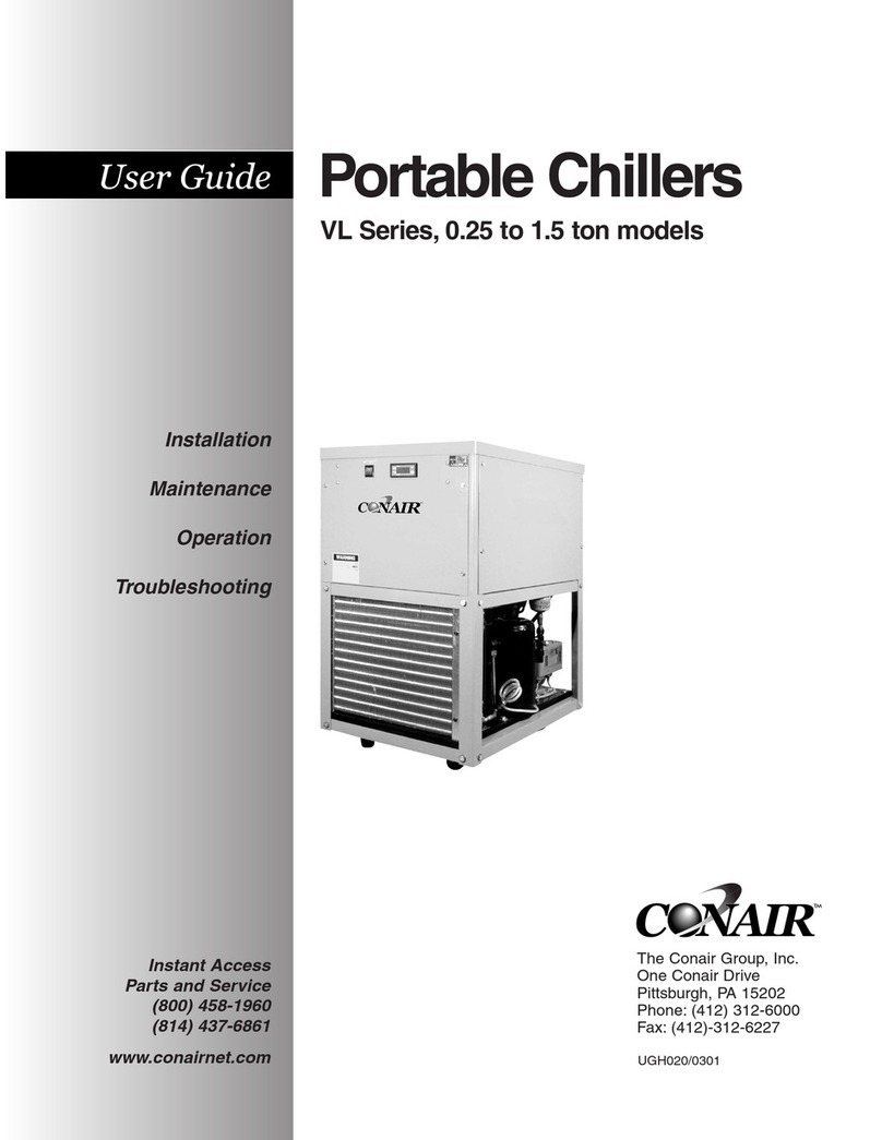
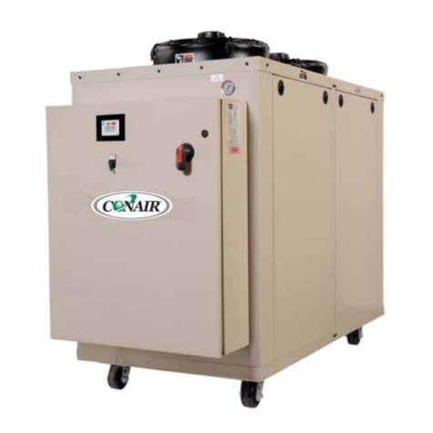
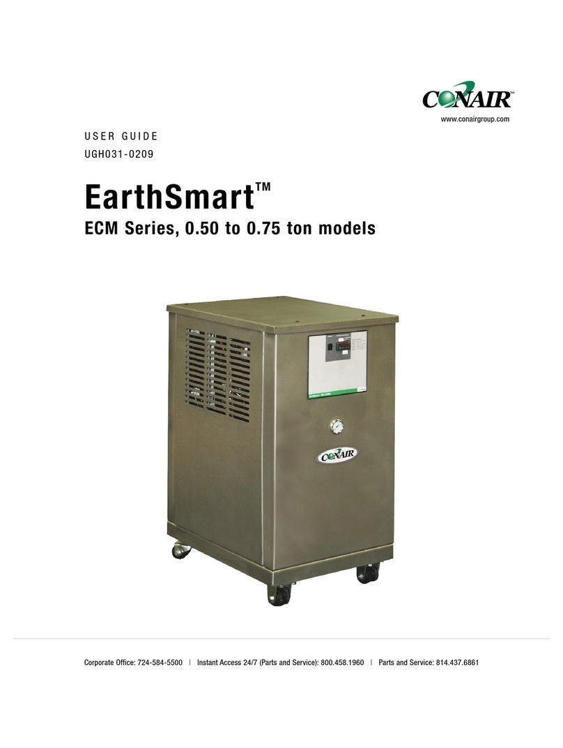
Conair MPA User manual


It’s a good idea to record the model and serial number(s) of
your equipment and the date you received it in the User
Guide. Our service department uses this information, along
with the manual number, to provide help for the specific
equipment you installed.
Please keep this User Guide and all manuals, engineering
prints and parts lists together for documentation of your
equipment.
Date:
Manual Number: UGH004/0999
Serial number(s):
Model number(s):
DISCLAIMER: The Conair Group, Inc., shall not be liable for errors
contained in this User Guide or for incidental, consequential dam-
ages in connection with the furnishing, performance or use of this
information. Conair makes no warranty of any kind with regard to
this information, including, but not limited to the implied warranties
of merchantability and fitness for a particular purpose.
Please record your
equipment’s model and
serial number(s) and
the date you received it
in the spaces provided.
Copyright 1999 All rights reserved
THE CONAIR GROUP, INC.

UGH004/0999 microKool Portable Chillers
TABLE OF
CONTENTS
INTRODUCTION . . . . . . . . . . . . . . . . . . .1-1
Purpose of the User Guide . . . . . . . . . . . . . . . . . . . . . . . . .1-2
How the guide is organized . . . . . . . . . . . . . . . . . . . . . . . .1-2
Your responsibility as a user . . . . . . . . . . . . . . . . . . . . . . .1-2
ATTENTION: Read this so no one gets hurt . . . . . . . . . . .1-3
DESCRIPTION . . . . . . . . . . . . . . . . . . . .2-1
What is the microKool chiller? . . . . . . . . . . . . . . . . . . . . . .2-2
Typical applications . . . . . . . . . . . . . . . . . . . . . . . . . . . . . .2-2
How it works: Water-Cooled . . . . . . . . . . . . . . . . . . . . . . .2-3
How it works: Air-Cooled . . . . . . . . . . . . . . . . . . . . . . . . .2-4
Features . . . . . . . . . . . . . . . . . . . . . . . . . . . . . . . . . . . . . . .2-5
Specifications: Water-Cooled . . . . . . . . . . . . . . . . . . . . . . .2-6
Specifications: Air Cooled . . . . . . . . . . . . . . . . . . . . . . . . .2-7
Freeze protection requirements . . . . . . . . . . . . . . . . . . . . .2-8
INSTALLATION . . . . . . . . . . . . . . . . . . . .3-1
Unpacking the boxes . . . . . . . . . . . . . . . . . . . . . . . . . . . . .3-2
Preparing for installation . . . . . . . . . . . . . . . . . . . . . . . . . .3-3
Connecting the proces and water supply lines . . . . . . . . . . .3-4
Connecting the main power . . . . . . . . . . . . . . . . . . . . . . . .3-5
Testing the installation . . . . . . . . . . . . . . . . . . . . . . . . . . . .3-6
Entering setpoint deviation parameters . . . . . . . . . . . . . . . .3-7
Initial setup . . . . . . . . . . . . . . . . . . . . . . . . . . . . . . . . . . . .3-8
Changing temperature units . . . . . . . . . . . . . . . . . . . . . . . .3-9
Enabling and disabling passcode protection . . . . . . . . . . .3-10
Selecting the temperature control point (PC-2 control) . . . . . .3-12
Enabling the Auto Start feature (PC-2 control) . . . . . . . . . . . .3-14
Activating SPI communication . . . . . . . . . . . . . . . . . . . . .3-16
OPERATION . . . . . . . . . . . . . . . . . . . . . .4-1
PC-1 control features . . . . . . . . . . . . . . . . . . . . . . . . . . . . .4-2
PC-2 control features . . . . . . . . . . . . . . . . . . . . . . . . . . . . .4-3
Positioning the control panel . . . . . . . . . . . . . . . . . . . . . . .4-4
Starting the chiller . . . . . . . . . . . . . . . . . . . . . . . . . . . . . . .4-5
Entering passcodes . . . . . . . . . . . . . . . . . . . . . . . . . . . . . . .4-6
Stopping the chiller . . . . . . . . . . . . . . . . . . . . . . . . . . . . . .4-7
Using the pumpdown feature (PC-2 control) . . . . . . . . . . . . . .4-9
Performing an Auto Tune . . . . . . . . . . . . . . . . . . . . . . . . .4-10
MAINTENANCE . . . . . . . . . . . . . . . . . . . .5-1
Preventative maintenance schedule . . . . . . . . . . . . . . . . . . .5-2
Cleaning evaporators . . . . . . . . . . . . . . . . . . . . . . . . . . . . .5-4
Cleaning condensers . . . . . . . . . . . . . . . . . . . . . . . . . . . . .5-4
Refilling the tank. . . . . . . . . . . . . . . . . . . . . . . . . . . . . . .5-5
Checking refrigerant charge . . . . . . . . . . . . . . . . . . . . . . . .5-6
i

microKool Portable Chillers UGH004/0999
TABLEOF
CONTENTS
MAINTENANCE . . . . . . . . . . . . . . .(continued)
Performing System Tests . . . . . . . . . . . . . . . . . . . . . . . . . .5-7
The Key/Display Test . . . . . . . . . . . . . . . . . . . . . . . . . . . . .5-8
Input Test . . . . . . . . . . . . . . . . . . . . . . . . . . . . . . . . . . . . . .5-9
Output Test . . . . . . . . . . . . . . . . . . . . . . . . . . . . . . . . . . .5-10
Disabling and Enabling Outputs . . . . . . . . . . . . . . . . . . . .5-11
Calibrating Temperature Sensors . . . . . . . . . . . . . . . . . . .5-12
Logging Operating Hours . . . . . . . . . . . . . . . . . . . . . . . .5-13
TROUBLESHOOTING . . . . . . . . . . . . . . . .6-1
Before Beginning . . . . . . . . . . . . . . . . . . . . . . . . . . . . . . . .6-2
A Few Words of Caution . . . . . . . . . . . . . . . . . . . . . . . . . .6-2
How to Identify the Cause of a Problem . . . . . . . . . . . . . . .6-3
DIAGNOSTICS
Shut Down Alarms . . . . . . . . . . . . . . . . . . . . . . . . . . . . . . .6-4
Warning Alarms . . . . . . . . . . . . . . . . . . . . . . . . . . . . . . . .6-10
System Alarms . . . . . . . . . . . . . . . . . . . . . . . . . . . . . . . . .6-11
Chiller Will Not Power Up . . . . . . . . . . . . . . . . . . . . . . . .6-12
REPAIR
Checking and Replacing Fuses . . . . . . . . . . . . . . . . . . . . .6-13
Resetting and Replacing Overloads . . . . . . . . . . . . . . . . .6-14
Replacing the Motherboard . . . . . . . . . . . . . . . . . . . . . . .6-15
Replacing the compressor contactor . . . . . . . . . . . . . . . . .6-16
Checking the unloader valve . . . . . . . . . . . . . . . . . . . . . .6-17
Replacing the freezestat . . . . . . . . . . . . . . . . . . . . . . . . . .6-18
APPENDIX
Customer Service Information . . . . . . . . . . . . . . . . . . . . . .A-1
Warranty/Guarantee Information . . . . . . . . . . . . . . . . . . . .A-2
microKool SPI commands . . . . . . . . . . . . . . . . . . . . . . . . .B-1
PARTS/DIAGRAMS
PC-1 Wiring Diagram . . . . . . . . . . . . . . . . . . . . . . . . . . .PD-2
PC-1 Circuit Board . . . . . . . . . . . . . . . . . . . . . . . . . . . . .PD-3
PC-2 Wiring Diagram . . . . . . . . . . . . . . . . . . . . . . . . . . .PD-4
PC-2 Circuit Board . . . . . . . . . . . . . . . . . . . . . . . . . . . . .PD-5
Parts Lists
ii

1-1
UGH004/0999 microKool Portable Chillers
●●Purpose of the User Guide . . . .1-2
●●How the guide is organized . . . .1-2
●●Your responsibilities as a user .1-2
●●ATTENTION: Read this so
no one gets hurt . . . . . . . . . . .1-3
INTRODUCTION

microKool Portable Chillers UGH004/0999
1-2 INTRODUCTION
This User Guide describes the Conair microKool water-cooled
and air-cooled portable chillers and explains step-by-step how
to install, operate, maintain and repair this equipment.
Before installing this product, please take a few moments to
read the User Guide and review the diagrams and safety infor-
mation in the instruction packet.You also should review man-
uals covering associated equipment in your system. This
review won’t take long, and it could save you valuable instal-
lation and operating time later.
Symbols have been used to help organize the User Guide and
call your attention to important information regarding safe
installation and operation.
Symbols within triangles warn of conditions that could
be hazardous to users or could damage equipment.
Read and take precautions before proceeding.
Numbers within shaded squares indicate tasks or steps
to be performed by the user.
A diamond indicates the equipment’s response to an
action performed by the user.
An open box marks items in a checklist.
A shaded circle marks items in a list.
You must be familiar with all safety procedures concerning
installation, operation and maintenance of this equipment.
Responsible safety procedures include:
●Thorough review of this User Guide, paying particular
attention to hazard warnings, appendices and related dia-
grams.
●Thorough review of the equipment itself, with careful
attention to voltage requirements, intended uses and
warning labels.
●Thorough review of instruction manuals for associated
equipment.
●Step-by-step adherence to instructions outlined in this
User Guide.
PURPOSE OF
THE USER
GUIDE
HOW THE
GUIDE IS
ORGANIZED
1
◆
❒
●
YOUR
RESPONSIBILITY
ASAUSER

UGH004/0999 microKool Portable Chillers INTRODUCTION 1-3
We design equipment with the user’s safety in mind. You can
avoid the potential hazards identified on this machine by
following the procedures outlined below and elsewhere in the
User Guide.
ATTENTION:
READ THIS SO NO
ONE GETS HURT
WARNING: Electrical shock hazard
This equipment is powered by three-phase
main voltage, as specified on the machine seri-
al tag and data plate.
Always disconnect and lock out the incoming
main power source before opening the electri-
cal enclosure or performing non-standard oper-
ating procedures, such as troubleshooting or
maintenance. Only qualified personnel should
perform procedures that require access to the
electrical enclosure while power is on.
WARNING: Improper installation,
operation or servicing may result in
equipment damage or personal injury.
This equipment should be installed, adjusted,
and serviced by qualified technical personnel
who are familiar with the construction, opera-
tion and potential hazards of this type of equip-
ment.
All wiring, disconnects and fuses should be
installed by qualified electrical technicians in
accordance with electrical codes in your region.
Always maintain a safe ground. A properly
sized conductive ground wire from the incoming
power supply must be connected to the chassis
ground terminal inside the electrical enclosure.
Improper grounding can result in personal
injury and erratic machine operation.
Do not operate the equipment at power levels
other than what is specified on the the equip-
ment serial tag and data plate.
Only certified refrigerant technicians should
recharge the refrigerant used in this system.


2-1
UGH004/0999 microKool Portable Chillers
●●What is the microKool chiller? .2-2
●●Typical applications . . . . . . . . . .2-2
●●How it works:
Water-cooled models . . . . . . . .2-3
●●How it works:
Air-cooled models . . . . . . . . . . .2-4
●●Features . . . . . . . . . . . . . . . . . . .2-5
●●Specifications:Water-cooled . . .2-6
●●Specifications: Air-cooled . . . . .2-7
●●Freeze protection
requirements . . . . . . . . . . . . . .2-8
DESCRIPTION

The microKool portable chillers are designed to provide
chilled water for industrial applications requiring 24-hour-a-
day performance.
Operation of air-cooled and water-cooled units differ only in
the medium used to remove heat from the refrigerant in the
condensers.
Water-cooled models use 85° F (29° C) cooling tower water,
and are equipped with high efficiency tube-in-tube condensers
with water regulating valves.
Air-cooled models use 95° F (35° C) ambient air and alu-
minum-fin, copper-tube condensers. Units above 1.5 Hp
include automatic fan cycling controls.
Units are totally self-contained for easy, economical installa-
tion. To operate, simply connect the power source, process
piping and fill with water or an industrial antifreeze mixture.
The standard PC-1 microprocessor control displays setpoint
and actual temperature of the process fluid, and provides SPI
communication. Nine operating and fault indicator lights dis-
play the status of the chiller components.
The enhanced PC-2 control offers the same features as the
standard control plus autostart capabilities, which enables the
chiller to start automatically with a timing device or the start-
ing of the primary process machine.
These chillers are ideal for cooling to maintain process tem-
peratures in an injection molding machine or extruder and
wherever you need a small, moveable cooling unit.
Capacities range from 1.2 to 10.2 tons. Standard operating set-
points are between 20° F (-7° C) and 65° F (19° C) LWT.
Adequate freeze protection is required.
Choose water-cooled portable chillers:
●for maximum capacity and minimal maintenance.
●when maintaining ambient air temperature is important,
such as an air-conditioned environment.
●when tower water or another inexpensive water source is
available.
Choose air-cooled portable chillers.
●when plant water supply is inadequate or limited.
●when process heat must be extracted and used for space
heating.
WHAT IS THE
MICROKOOL
CHILLER?
microKool Portable Chillers UGH004/0999
2-2 DESCRIPTION
TYPICAL
APPLICATIONS

Water-cooled models use tube-in-tube heat exchangers to
condense the hot, compressed, refrigerant gas from the
compressor to a cool liquid.
The cool liquid refrigerant passes through a filter/dryer,
which protects the system from moisture or other contami-
nants. An in-line sight glass gives a visual indication of
proper refrigerant charge and any dangerous moisture pre-
sent in the system.
The refrigerant passes through a thermal expansion valve,
where it expands, cools and is precisely metered into the
refrigerant heat exchanger (evaporator).
The evaporator removes the heat from the process fluid.
HOW IT WORKS:
WATER COOLED
UGH004/0999 microKool Portable Chillers DESCRIPTION 2-3
Typical water-cooled plumbing diagram

HOW ITWORKS:
AIR COOLED
microKool Portable Chillers UGH004/0999
2-4 DESCRIPTION
Air-cooled models use aluminum-finned, copper tube con-
densers to condense the hot, compressed, refrigerant gas
from the compressor to a cool liquid.
The cool liquid refrigerant passes through a filter/dryer,
which protects the system from moisture or other contami-
nants. An in-line sight glass gives a visual indication of
proper refrigerant charge and any dangerous moisture pre-
sent in the system.
The refrigerant passes through a thermal expansion valve,
where it expands, cools and is precisely metered into the
refrigerant heat exchanger (evaporator).
The evaporator removes the heat from the process fluid.
Typical air-cooled plumbing diagram

UGH004/0999 microKool Portable Chillers DESCRIPTION 2-5
Molded Plastic
Reservoirs
Large,thick-walled,
insulated polyethylene
reservoirs provide
corrosion-free operation.
Low-water level sensors,
external fill ports and level
indicators are standard.
Water Connections
All chilled water and con-
denser water connections
are welded to the struc-
ture. Every unit includes
bronze chilled water sup-
ply and return valves.
High Efficiency Compressors
All microKool chillers are equipped with quiet
Copeland hermetically sealed compressors. Hot-
gas bypass capacity control is standard, permit-
ting efficient operation with cooling loads as low
as 25% of rated chiller capacities.
Corrosion-Free Evaporators
On models through 7.5 Hp, chilled water flows through heavy
gauge tube-in-tube evaporators.The water comes in contact with
only copper surfaces, eliminating corrosion and scale build-up
that can severely reduce chiller efficiency. Low pressure drops,
averaging less than 2 psi, result in more flow to the process.
Performance-engineered condensers
Water-cooled models are equipped
with high efficiency, non-ferrous
tube-in-tube condensers and water
regulating valves. Air-cooled mod-
els have aluminum fin, copper tube
condensers. MPA models with
compressors above 1.5 Hp have
automatic fan cycling controls.
Control Extension
Controls can be extended
approximately 11 inches
from the control base.
FEATURES
Water-cooled
unit shown

SPECIFICATIONS: MPW (WATER COOLED)
microKool Portable Chillers UGH004/0999
2-6 DESCRIPTION
MODEL MPW-1.5 MPW-2 MPW-3 MPW-4 MPW-5 MPW-7.5 MPW-10
Performance characteristics
Capacity {tons}
*
1.4 1.8 3.1 4.1 4.8 7.6 10.2
Compressor Hp {kW} 1.5 {1.12} 2 {1.49} 3 {2.24} 4 {2.98} 5 {3.73} 7.5 {5.59} 10 {7.45}
Pump Hp {kW}
†
0.33 {0.246} 0.50 {0.373} 0.75 {0.559} 1.5 {1.12} 1.5 {1.12} 1.5 {1.12} 1.5 {1.12}
Chilled water flow gpm {l/min}
‡
3.4 {12.9} 4.5 {17.0} 7.5 {28.3} 9.9 {37.5} 11.4 {43.2} 18.2 {68.9} 24.5 {81.0}
Chilled water pressure psi {bar}
§
20 {1.4} 26 {1.8} 34 {2.3} 38 {2.6} 38 {2.6} 37.5 {2.6} 37 {2.5}
Reservoir capacity gal (l) 10 {37.9} 10 {37.9} 10 {37.9} 30 {114} 30 {114} 30 {114} 30 {114}
Condenser water flow gpm {l/min} 4.3 {16.3} 5.6 {21.2} 9.4 {35.6} 12.4 {47.0} 14.3 {54.2} 22.8 {86.4} 30.6 {116.0}
Dimensions inches {mm}
A - Height
**
45 {1143} 45 {1143} 45 {1143} 56 {1422} 56 {1422} 70 {1778} 70 {1778}
B - Depth 32 (812} 32 {812} 32 {812} 48 {812} 48 {812} 48 {812} 48 {812}
C - Width 29 {737} 29 {737} 29 {737} 34 {737} 34 {737} 34 {737} 34 {737}
Weight lb {kg}
Shipping weight 550 {249} 755 {342} 755 {342} 1010 {458} 1010 {458} 1250 {567} 1250 {567}
Installed weight 420 {190} 585 {265} 585 {265} 840 {381} 840 {381} 1080 {490} 1080 {490}
Utility requirements
Water connections NPT (female) inches 1 1 1 1.5 1.5 1.5 1.5
Process and condenser water inches 1 1 1 1.5 1.5 1.5 1.5
Voltages running and full load amps run full run full run full run full run full run full run full
208V/3 phase/60hz 8.8 15.5 13.7 15.9 17.7 22.3 23.9 28.3 27.0 30.5 34.9 41.5 44.2 50.8
230V/3 phase/60hz 8.0 14.0 12.4 14.4 16.0 20.2 21.6 25.6 24.4 27.6 31.6 37.6 40.0 46.0
460V/3 phase/60hz 4.0 7.0 6.2 7.2 8.0 10.1 10.8 12.8 12.2 13.8 15.8 18.8 20.0 23.0
575V/3 phase/60hz 3.2 5.6 5.0 5.8 6.4 8.1 8.6 10.2 9.8 11.0 12.6 15.0 16.0 18.4
Flow Rate (gpm)
Pressure (psi)
SPECIFICATION NOTES
* Based on 50° F (10° C) water temperature (100% water) leaving the chiller, standard pump selections, 85° F (27° C) condenser water supply
@ 25 psi minimum. Consult factory for other conditions.
†Standard pump selection. Larger pumps available as options.
‡ Based on 50° F water temperature leaving the chiller and 60° F (15° C) water temperature returning to the chiller.
§Pressure at pump discharge.
** Control can be extended upward approximately 11 inches, which may or may not increase the overall height of the unit.
Specifications may change without notice. Check with a Conair representative for the most current information.
60 HZ PUMP PERFORMANCE CURVES

SPECIFICATIONS:MPA(AIR COOLED)
UGH004/0999 microKool Portable Chillers DESCRIPTION 2-7
MODEL MPA-1.5 MPA-2 MPA-3 MPA-4 MPA-5 MPA-7.5 MPA-11
Performance characteristics
Capacity {tons}
*
1.2 1.7 2.7 3.5 4.1 6.9 10.2
Compressor Hp {kW} 1.5 {1.12} 2.25 {2.05} 3.25 { 279.7} 4 {2.98} 5 {3.73} 9 {6.71} 12 {8.95}
Pump Hp (kW)
†
0.33 {0.246} 0.50 {0.373} 0.75 {0.559} 1.5 {1.12} 1.5 {1.12} 1.5 {1.12} 1.5 {1.12}
Chilled water flow gpm {l/min}
‡
2.8 {10.6} 4.2 {15.9} 6.4 {24.2} 8.5{32.1} 9.9 {37.5} 16.6 {62.8} 24.5 {92.7}
Chilled water pressure psi {bar}
§
20 {1.4} 26 {1.8} 34 {2.3} 38 {2.6} 38 {2.6} 37.5 {2.6} 37 {2.5}
Reservoir capacity gal {l} 10 {37.9} 30 {114} 30 {114} 30{ 114} 30 {114} 30 {114} 40.5 {153}
Number of condenser fans 1 2 2 2 2 2 4
Condenser fan power Hp {kW} 0.063 {0.047} 0.063 {0.047} 0.063 {0.047} 0.063 {0.047} 0.063 {0.047} 0.50 {0.047} 0.50 {0.047}
Condenser air flow ft3/min {l/min} 1050 {496} 1704 {804} 2420 {1142} 4237 {2000} 4237 {2000} 5300 {2501} 8400 {3964}
Dimensions inches {mm}
A - Height
**
45 {1143} 48 {1129} 48 {1129} 56 {1422} 56 {1422} 70 {1778} 76 {1930}
B - Depth 32 {812} 44 {1118} 44 {1118} 48 {1219} 48 {1219} 48 {1219} 48 {1219}
C - Width 29 {737} 29 {737} 29 {737} 34 {737} 34 {737} 34 {737} 40{1016}
Weight lb {kg}
Shipping weight 750 {340} 1000 {454} 1000 {454} 1200 {544} 1200 {544} 1400 {635} 1600 {726}
Installed weight 610 {277} 830 {376} 830 {376} 1030 {467} 1030 {467} 1230 {558} 1430 {649}
Utility Requirements
Water connections NPT (female) inches 1 1 1 1.5 1.5 1.5 1.5
Process water inches 1 1 1 1.5 1.5 1.5 1.5
Voltages running and full load amps run full run full run full run full run full run full run full
208V/3 phase/60hz 11.7 18.3 16.1 18.6 21.0 27.0 27.8 32.3 31.0 34.5 63.0 69.6 90.8 97.8
230V/3 phase/60hz 10.6 16.6 14.6 16.8 19.0 24.4 25.2 29.2 28.0 31.2 57.0 63.0 82.2 88.5
460V/3 phase/60hz 5.3 8.3 7.3 8.4 9.5 12.2 12.6 14.6 14.0 15.6 28.5 31.5 41.1 44.3
575V/3 phase/60hz 4.2 6.6 5.8 6.7 7.6 9.8 10.1 11.7 11.2 12.5 22.8 25.2 32.9 35.4
SPECIFICATION NOTES
* Based on 50° F (10° C) water temperature (100% water) leaving the chiller, standard pump selections, 95° F (35° C) ambient air conditions.
Consult factory for other conditions.
† Standard pump selection. Larger pumps available as options.
‡ Based on 50° F water temperature leaving the chiller 60° F (15° C) water temperature returning to the chiller.
§ Pressure at pump discharge.
** Control can be extended upward approximately 11 inches, which may or may not increase the overall height of the unit.
Specifications may change without notice. Check with a Conair representative for the most current information.
Flow Rate (gpm)
60 HZ PUMP PERFORMANCE CURVES
Pressure (psi)

FREEZE
PROTECTION
REQUIREMENTS
microKool Portable Chillers UGH004/0999
2-8 DESCRIPTION
60
50
40
30
20
10
0
-10
-20
-30
-40
-50
-60 2004060
80 100
40
30
20
10
0
-10
-20
-30
-40
-50
-60
-70
-80 2004060
80 100
Freeze Protection Requirements
by Unit Set Temperature
Freezing Points of Aqueous
Ethylene Glycol Solutions
Ethylene Glycol, % by weight
Temperature, degrees F to Process SetTemperature, degrees F

3-1
UGH004/0999 microKool Portable Chiller
●●Unpacking the boxes . . . . . . . . .3-2
●●Preparing for installation . . . . . .3-3
●●Connecting the water supply . .3-4
●●Connecting the main power . . .3-5
●●Testing the installation . . . . . . . .3-6
●●Entering setpoint
deviation parameters . . . . . . . .3-7
●●Initial setup . . . . . . . . . . . . . . . .3-8
●●Changing temperature units . . .3-9
●●Enabling and disabling
passcode protection . . . . . . .3-10
●●Selecting the temperature
control point
(PC-2 Control)
. . . . .3-12
●●Installing the Auto Start
feature . . . . . . . . . . . . . . . . . .3-14
●●Activating SPI
communication . . . . . . . . . . . .3-16
INSTALLATION

UNPACKING THE
BOXES
microKool Portable Chillers UGH004/0999
3-2 INSTALLATION
Carefully remove the chiller and components from
their shipping containers, and set upright.
Remove all packing material,protective paper,
tape, and plastic. Check inside the electrical enclosure
and behind the side panels for accessories or hardware
that may have been placed there for shipping.
Carefully inspect all components to make sure no
damage occurred during shipping, and that you have all
the necessary hardware. If damage is found, notify the
freight company immediately.
Take a moment to record serial numbers and
specifications in the blanks provided on the back of the
User Guide’s title page. The information will be helpful if
you ever need service or parts.
You are now ready to begin installation.
Complete the preparation steps on the next page.
1
2
3
4
5
MicroKool Portable Chillers come fully assembled.

UGH004/0999 microKool Portable Chillers INSTALLATION 3-3
The microKool chiller is easy to install, if you plan the loca-
tion and prepare the area properly.
Position the chiller as close to the process
machine as possible.
Make sure the installation area provides:
❒❒A three-phase power source supplying the correct
current for your chiller model. Check the serial tag on the
side of the electrical enclosure for the required voltage,
phase, frequency, full load amps, disconnect fuse size and
minimum wire connection size. Field wiring should be
completed by qualified personnel to the planned location
for the chiller. All electrical wiring should comply with
your region’s electrical codes.
❒❒A clean, well-ventilated environment.
The room temperature should not exceed 110° F (43° C)
with 95% non-condensing humidity and should not fall
below 55° F (12° C).
❒❒Minimum clearance for safe operation and mainte-
nance. Nothing should be placed on top of the unit while
the unit is operating. All models require a minimum clear-
ance of 5 ft. around the perimeter for servicing. Models
equipped with fans also require unrestricted outlet air flow.
❒❒A source of water for cooling on water-cooled units.
City, tower or chiller water may be used, as long as the
supply pressure is at least 25 psi and not more than 85 psi.
Install plumbing for process and cooling lines.
See the specification tables for the correct line and fitting
sizes. Larger line sizes are acceptable as long as they are
reduced at the chiller connections. Smaller line sizes are
not recommended.
PREPARING FOR
INSTALLATION
1
2
Process machine
Chiller
Alternate
locations
3

The chiller process inlets and outlets must be connected to the
plumbing that will circulate the temperature-controlled water
or fluid through the process. Cooling water inlets and outlets
are connected to the cooling water supply.
Remove the shipping pipe plug from the female
connections on the back of the chiller.
Install pipe to the rear of the chiller.
Use appropriately sized male NPT piping for the process
connections and the MPW condenser water connections.
Pipe and pipe threads must be clean and new. Clean
threads with solvent, removing all oil, grease and dirt.
Allow the threads to dry before proceeding.
Coat the pipe threads with thread sealant.
Follow the sealant manufacturer’s directions.
Connect the male pipe to the appropriate
female connection on the back of the unit.
Connections are labeled on the chiller. Start by hand until
the threads engage, then use a pipe wrench to tighten the
connection only enough to prevent leaks.
Do not over-tighten!
CONNECTING
PROCESS AND
WATER SUPPLY
LINES
microKool Portable Chillers UGH004/0999
3-4 INSTALLATION
1
2
3
4
Tools for installation:
❒ Pipe wrench large enough
for a 2-inch pipe
❒ Premium quality Teflon
thread sealant
Process connections (NPT):
MPW-1.5 MPW-2 MPW-3 MPW-4 MPW-5 MPW-7.5 MPW-10
MPA-1.5 MPA-2 MPA-3 MPA-4 MPA-5 MPA-7.5 MPA-11
1 in. 1 in. 1 in. 1.5 in. 1.5 in. 1.5 in. 1.5 in.
Condenser water connections (NPT):
MPW-1.5 MPW-2 MPW-3 MPW-4 MPW-5 MPW-7.5 MPW-10
1 in. 1 in. 1 in. 1.5 in. 1.5 in. 1.5 in. 1.5 in.
NOTE: Make sure the
chiller tank is full of
process fluid before
you begin operating.
Use a glycol mixture if
operating temperatures
are below 45° F. See
F
REEZE
P
ROTECTION
R
EQUIREMENTS
.
Tank
fill port
Condenser
water in
From
Process
Condenser
water out
Condenser water
connections on
MPW models only
To
Process
Tank level
sight glass
This manual suits for next models
3
Table of contents
Other Conair Chiller manuals
Popular Chiller manuals by other brands

York
York YCAS0130 Installation, operation & maintenance manual

Vinservice
Vinservice LIFE 50 OPERATION AND MAINTENANCE BOOK

Robur
Robur GA ACF Installation, use and maintenance manual

Trane
Trane RTWD Installation operation & maintenance

Temptek
Temptek CF Series instruction manual

Christie
Christie SMC HRS-040 Installing and setting up