Concoa 580 6001 Owner's manual

Micron Filter Assembly
INSTALLATION AND OPERATION INSTRUCTIONS
NOT FOR OXYGEN OR OTHER OXIDIZING GASES
BeforeInstallingorOperating,ReadandComplywithTheseInstructions
Controls Corporation of America
1501 Harpers Road • Virginia Beach, VA 23454
To Order Call 1-800-225-0473 or 757-422-8330 • Fax 757-422-3125
www.concoa.com
January2002
Certified ISO 9001
ADI 3205-B
580 6001

2
USER RESPONSIBILITY
This equipment will perform in conformity with the description contained in this manual and accompanying
labels and/or inserts when installed, operated, maintained, and repaired in accordance with the instructions
provided. This equipment must be checked periodically. Improperly working equipment should not be used.
Parts that are broken, missing, worn, distorted or contaminated, should be replaced immediately. CONCOA
recommends that a telephone or written request for service advice be made to the CONCOA Warranty Admin-
istrator in Virginia Beach, Virginia.
This equipment or any of its parts should not be altered without the prior written approval by CONCOA. The
user of this equipment shall have the sole responsibility for any malfunction that results from improper use,
faulty maintenance, damage, improper repair, or alteration by anyone other than CONCOA or a service facility
designated by CONCOA.
This filter assembly is designed to remove system contaminants as small as 2 micron in inert gas service. The
filter element can be replaced without removing the filter body from the system.
Replacement 2 micron filter part number: 830 0318
In the event of equipment failure, call the CONCOA Customer Assistance Line: 1-800-225-0473. Please be
prepared to provide the model number and serial number of the equipment involved, in addition to some
details regarding its application. This would include inlet and outlet pressures, flow rate, environmental condi-
tions, and gas service. Things to consider before removing the system from the box….
1. Know the properties and special handling requirements of the gas being used. Many specialty gases are
quite dangerous (flammable, toxic, corrosive, simple asphixiant, or oxidizers). Equipment failure or
misuse may lead to problems such as a release of gas. Proper safety measures should be established to
handle these and other component failures.
2. Be sure that the assembly purchased is suitable for the gas and type of service intended. The regulator
label provides the following information:
a.Model number
b.Serial number
c.Maximum inlet pressure
Be sure that the equipment received conforms to the order specifications. The user is responsible for
selecting equipment compatible with the gas in use, and conditions of pressure, temperature, flow, etc.
Selection information can be found in CONCOA technical data sheets. In addition, CONCOA repre-
sentatives are trained to aid in the selection process.
3. Inspect the assembly upon receipt to be sure that there is no damage or contamination. Pay particular
attention to connecting threads. While CONCOA assembles system components to exacting leak-
tight standards, the customer should also inspect for any loosening of parts that may occur in shipping
or installation. Loose parts may be dangerously propelled from an assembly. If there are adverse signs
(leakage or other malfunction), return the assembly to the supplier. While it is advised that soiled
products be returned for cleaning, simple external dust or grease may be removed by a clean cloth and
if required with aqueous detergent suitable for the application. If there are signs of internal contamina-
tion, return to the supplier.
CUSTOMER ASSISTANCE
DESCRIPTION

3
GENERAL SAFETY PRACTICES
4. Before system startup, it is recommended that all systems be pressure tested, leak tested, and purged
with an inert gas such as nitrogen. To accomplish this with connections other than a CGA 580, it will
be necessary to use an adapter. The recommended use of an adapter is for temporary use, for start-up
and system checks only. Adapters should never be used on a permanent basis.
Comply with precautions listed in C.G.A. Pamphlet P-1, Safe Handling of Compressed Gases in Containers.
Consult the cylinder distributor for the proper use of cylinders and for any restrictions on their use (such as flow
rate and temperature requirements).
Store cylinders with valve caps screwed on, and cylinders chained to a supporting wall or column.
Handle cylinders carefully and only with valve caps screwed on. The cap will reduce the chance that the
cylinder valve will break off if the cylinder is accidentally dropped or falls over. The cap also protects the
cylinder valve from damage to screw threads, which could cause leaky connections.
All manifolds used with flammable gases should be provided with approved flashback arrestors to stop any
burning gas in the pipeline from getting back to the manifold or cylinders.
No smoking should be permitted near oxygen, nitrous oxide, any other oxidizer, flammable gases, or flammable
mixtures, or in areas where cylinders are stored.
Where oxygen or nitrous oxide is used, the manifold and cylinders must be kept clean. No oil, grease, or
combustible substances should come in contact with oxygen or nitrous oxide storage or handling equipment.
Such materials in contact with oxygen or nitrous oxide are readily ignitable and when ignited, will burn in-
tensely.
Never use an open flame when leak testing.
Always open valves slowly when high-pressure gases are being used.
Always be sure that a cylinder contains the correct gas before connecting it to any manifold.
Always leak-test any manifold or distribution pipeline before using.
Always be sure that the gas in a pipeline is the correct gas for the intended use.
Always close all cylinder valves before disconnecting cylinders from a manifold.
Always remove all empty cylinders from a manifold before connecting full cylinders.
Always test cylinders to be sure the cylinders are full before connecting to a manifold.
Not for use with Oxygen, oxidizing gas, corrosive or toxic gases.
Maximum inlet pressure, 200 PSIG.

4
GENERAL INSTALLATION AND OPERATION
All gas distribution piping systems must meet the appropriate industrial standards for the intended service and
must be thoroughly cleaned before using. For the United States, some applicable safety rules and precautions
are listed below:
1. American National Standards Institute standard Z49.1, Safety in Welding and Cutting, American
Welding Society, 2501 NW Seventh Street, Miami, Florida 33125
2. N.F.P.A. Standard 51, Oxygen-Fuel Gas systems for Welding and Cutting, N.F.P.A., 470 Atlantic Av-
enue, Boston, Massachusetts 02210
3. N.F.P.A. Standard 51B, Cutting and Welding Processes (same address as #2).
4. CONCOA publication ADE 872, Safety Precautions in Welding and Cutting.
5. Local Ordinances
6. O.S.H.A. Standard 29 CFR
7. C.G.A. Pamphlet C-4, American National Standard Method of Marking Portable Compressed Gas
Containers to Identify the Material Contained.
8. C.G.A. Pamphlet G-4, Oxygen – Information on the properties, manufacture, transportation, storage,
handling, and use of oxygen.
9. C.G.A. Pamphlet G-4.1, Equipment Cleaned for oxygen service.
10. C.G.A. Pamphlet G-4.4, Industrial Practices for Gaseous Oxygen Transmission and Distribution Pip-
ing Systems.
11. C.G.A. Pamphlet G-5, Hydrogen – Information on the properties, manufacture, transportation, stor-
age, handling, and use of hydrogen.
12. C.G.A. Pamphlet G-6, Carbon Dioxide – Information on the properties, manufacture, transportation,
storage, handling, and use of carbon dioxide.
13. C.G.A. Pamphlet G-6.1, Standard for Low Pressure Carbon Dioxide Systems at Consumer Sites.
14. C.G.A. Pamphlet P-1, Safe Handling of Compressed Gases in Containers.
15. C.G.A. Safety Bulletin SB-2, Oxygen Deficient Atmospheres.
*C.G.A. pamphlets can be obtained from the Compressed Gas Association, 1235 Jefferson Davis Highway,
Arlington, VA 22202-3239, (703) 979-0900. Publications: (703) 979-4341. Fax: (703) 979-0134.
Keep all cylinders and manifolds away from any source of high temperature over 120°F (50°C) or possible fire
hazards. High-pressure gas contained in a closed cylinder becomes increasingly dangerous when exposed to
high temperature because pressure increases and the strength of the cylinder decreases. Manifolds installed in
open locations should be protected from weather conditions. During winter, protect the manifold from ice and
snow. In summer, shade the manifold and cylinders from continuous exposure to direct sunlight. Always leave
access to the manifold for cylinder replacement.
INSTALLING INLET AND OUTLET CONNECTIONS:
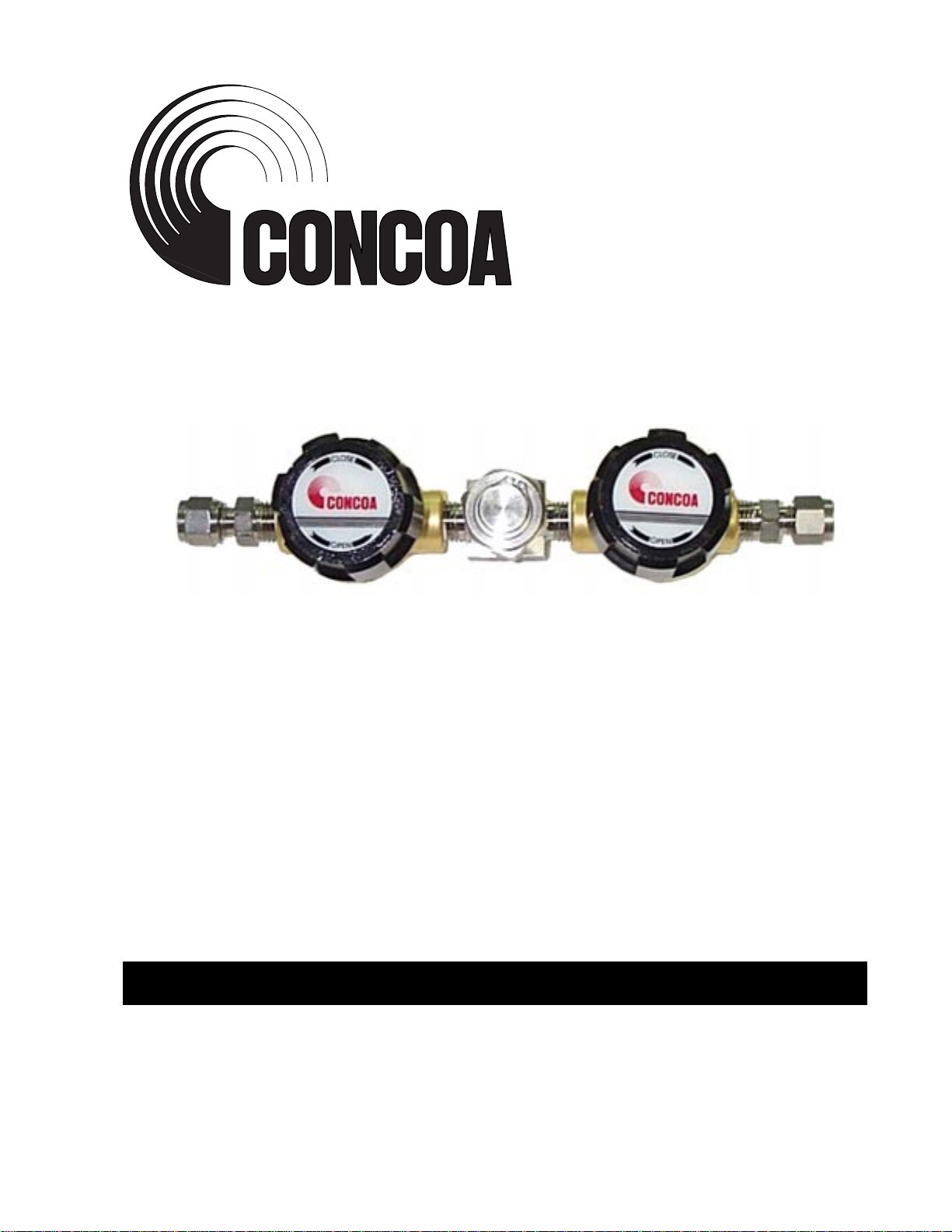
The filter assembly connects upstream of user equipment by ¼ Swagelock tube fittings in and out. The flow
arrow located on the filter body indicates the correct direction of the flow of gas. Assemble tube fittings in
accordance with Swagelock instructuions found on page 7 of this instruction manual.
CONCOA uses Teflon tape on all of its regulator NPT connections. Follow these rules when using Teflon tape.
Inspect the NPT threads and if necessary, clean the fitting to remove any dirt or thread sealant that remains on
the threads. Start the Teflon tape on the second thread as shown in Figure 1; make sure the tape does not overlap
the end of the fitting. As the tape is wrapped in the direction of the thread spiral, pull tightly on the end of tape
LOCATION

5
so that the tape conforms to the threads. Wrap the tape around the threads twice. Cut off the excess tape and
press the end firmly into the threads.
Install, purge, and open both valves on filter assembly. If undesirable flow or pressure drop occurs, change filter
element as described in the SERVICE section of this ADI.
On regular intervals, the system should be checked for leaks and proper function (see trouble shooting). Any
leaks in the system should be corrected immediately.
Filter Replacement Instructions
Disassembly
1. Close inlet valve on Assembly.
2. Close outlet valve after inlet valve is completely
closed.
3. Slowly loosen bonnet nut to vent any pressure that
may be present. After all venting has stopped, re-
move bonnet assembly (bonnet nut, bonnet, spring
and retaining ring) from body.
4. If replacing filter element, remove used element
and discard.
Re-assembly
1. Before reassembling the filter, be certain all com-
ponents are clean and free of contamination.
2. Align the new element parallel to the filter bore,
positioning the open end of the element towards the body, and press securely in place.
Figure 1. Pictorial view of tape seal installation.
OPERATION
MAINTENANCE
Figure 2., Filter Diagram.

6
3. Lubricate gasket with thin film of system compatibile lubricant. Place gasket on body seal surface.
4. If installing a new spring, press the spring into the bonnet assembly with the large end of the spring
first.
5. Holding the body stationary, thread the bonnet assembly onto the body finger-tight.
6. Tighten the bonnet nut to 500 in-lbs (75 N-m) torque.
7. Test the filter for proper operation and leak tight sealing.
A unit that is not functioning properly should not be used. It is recommended that all servicing be done by a
service facility authorized by CONCOA. Contact CONCOA Customer Service in Virginia Beach, Virginia for
systems still covered by the warranty. For items not covered by the warranty, contact the nearest CONCOA
District Sales Office for assistance. Contact CONCOA by phone toll-free 1-800-225-0473, FAX: 1-757-422-
If so advised, the unit should be sent to a service facility authorized by CONCOA. Do the following before
shipping:
1. Adequately package the system. If possible package in the original shipping container.
2. Ship prepaid.
3. Include a statement of the observed deficiency.
4. Indicate the gas service that the equipment was used on.
5. Purge all equipment before shipment to protect the transporter and service personnel. The purging is
especially important if the equipment has been in hazardous or corrosive gas service.
SERVICE
ADI 3205-B

Controls Corporation of America
1501 Harpers Road Virginia Beach, VA 23454
To Order Call 1-800-225-0473 or 757-422-8330 • Fax 757-422-3125
www.concoa.com
ADI 32B
Certified ISO 9001

8
Warranty Information
Thisequipment issold byCONTROLSCORPORATIONOF AMERICAunder thewarranties setforth inthe follow-
ing paragraphs. Such warranties are extended only with respect to the purchase of this equipment directly from CON-
TROLS CORPORATION OF AMERICA or its Authorized Distributors as new merchandise and are extended to the
first Buyer thereof other than for the purpose of resale.
Foraperiodofone(1)yearfromthedateoforiginaldelivery(90daysincorrosiveservice)toBuyerortoBuyer’sorder,this
equipment is warrantied to be free from functional defects in materials and workmanship and to conform to the descrip-
tion of this equipment contained in this manual and any accompanying labels and/or inserts, provided that the same is
properly operated under conditions of normal use and that regular periodic maintenance and service is performed or
replacements made in accordance with the instructions provided.The foregoing warranties shall not apply if the equip-
menthasbeenrepaired:otherthanbyCONTROLSCORPORATIONOFAMERICAoradesignatedservicefacilityor
in accordance with written instructions provided by CONTROLS CORPORATION OF AMERICA, or altered by
anyone other than CONTROLS CORPORATION OF AMERICA, or if the equipment has been subject to abuse,
misuse, negligence or accident.
CONTROLS CORPORATION OF AMERICA’s sole and exclusive obligation and Buyer’s sole and exclusive remedy
under the above warranties is limited to repairing or replacing, free of charge, at CONTROLS CORPORATION OF
AMERICA’s option, the equipment or part, which is reported to its Authorized Distributor from whom purchased, and
which if so advised, is returned with a statement of the observed deficiency, and proof of purchase of equipment or part
not later than seven (7) days after the expiration date of the applicable warranty, to the nearest designated service facility
duringnormalbusinesshours, transportationchargesprepaid,and whichuponexamination,isfoundnottocomplywith
the above warranties. Return trip transportation charges for the equipment or part shall be paid by Buyer.
CONTROLS CORPORATION OF AMERICA SHALL NOT BE OTHERWISE LIABLE FOR ANY DAMAGES
INCLUDING BUT NOT LIMITED TO: INCIDENTAL DAMAGES, CONSEQUENTIAL DAMAGES, OR
SPECIAL DAMAGES, WHETHER SUCH DAMAGES RESULT FROM NEGLIGENCE, BREACH OF WAR-
RANTY OR OTHERWISE.
THERE ARE NO EXPRESS OR IMPLIEDWARRANTIESWHICH EXTEND BEYOND THEWARRANTIES
HEREINABOVE SET FORTH. CONTROLS CORPORATION OF AMERICA MAKES NO WARRANTY OF
MERCHANTABILITY OR FITNESS FOR A PARTICULAR PURPOSE WITH RESPECT TO THE EQUIP-
MENT OR PARTS THEREOF.
Controls Corporation of America
1501 Harpers Road Virginia Beach, VA 23454
To Order Call 1-800-225-0473 or 757-422-8330 • Fax 757-422-3125
www.concoa.com
Table of contents
Popular Water Filtration System manuals by other brands

Polygroup
Polygroup SFX Series instructions

Quincy Compressor
Quincy Compressor QED-1250 Instruction book

Master Water Conditioning
Master Water Conditioning MBA Series Installation and operation manual

Crystal Quest
Crystal Quest Voyager Series Installation and operation guide

Kohler
Kohler K-6227 Installation and care guide

Axeon
Axeon Hydrogen user manual

Ispring
Ispring RO600 Series Installation instructions & user manual

Modena
Modena Igienico Series User manual book

Vivaria
Vivaria VarioPress 8000 operating instructions

ICT
ICT pcm Series instruction manual

OptiPure
OptiPure QT10-2 Installation, operation & maintenance manual

Brita
Brita SHS-102 installation instructions