10 SS-5, SS-5/3 | 1.00.01 www.mc-techgroup.com
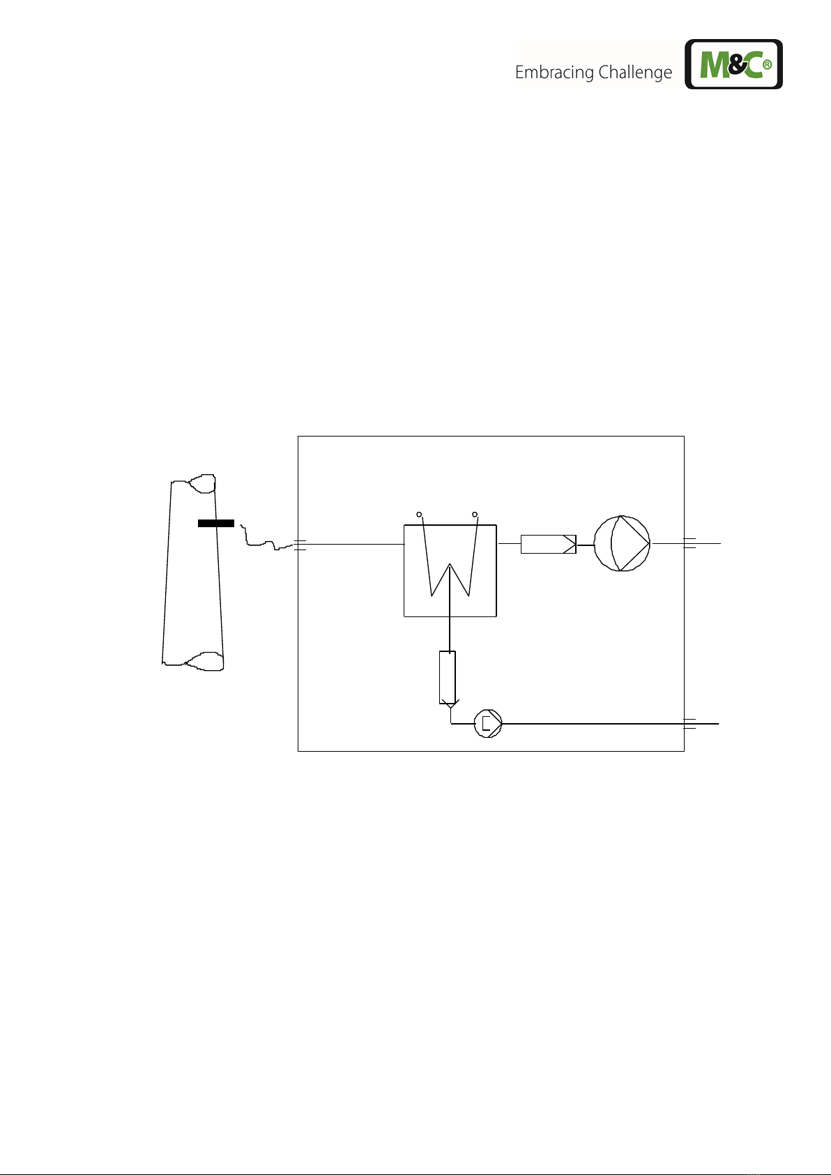
The preliminary filter FP-2T (2µm filter element fineness) installed in front of the gas measuring pump
ensures that the correct amount of solid matter is precipitated.
The sample gas pump is turned off and on automatically by means of an excess temperature contact
on the cooler (+8°C).
The resulting condensation is continually lead off by means of the SR25.1 peristaltic pump.
A preliminary filter, PF2 has been fitted in the condensation hose in between the heat exchanger and
peristaltic pump. This prevents particles in the condensate entering the pump.
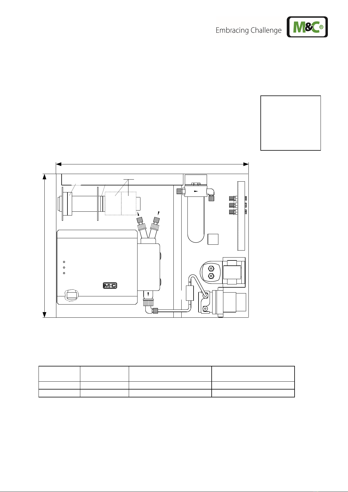
The 4/6mm hose connections for the condensate and measuring leads (11) are located on the right-
hand side of the case (see figure 2 and 3).
The ventilation grids located in the lid and the left-hand side of the case ensure that the equipment is
sufficiently ventilated.
Options
The gas conditioning and sampling system SS-5... consists of a maximum of 4 gas-measuring outlet
terminals. Additional flowmeters (FM 40), with needle valves, can be fitted to each of these terminals,
whereby the adjustment of the terminals is carriedout in accordance with the specified volume flow rate
(see 3.). The assembly bore holes in the gas-measuring outlet terminals and the flowmeter which are
not being used are sealed-off with caps.
In order to protect additionally connected analysers against fluid irruption, and increase the operational
safety of the entire system, we recommend that a fluid alarm sensor LA 1S be installed. In such a case,
the preliminary filter FP-2T, which is delivered with all models, will be replaced with the FP-2T-D
preliminary filter by the manufacturer. The LA1.4 electronic is located on the clamp mounting rail in
the upper part of the case. In the event of a fluid irruption, the LA electronics automatically turns off the
sample gas pump. The alarm will be raised by means of a red LED. If the equipment is functioning
properly, i.e. no alarm, a green LED will be on.
The SS-5... can also be equipped with an additional gas measuring inlet terminal (see figure 3, Article
No. 01 G 9060) in order to connect a heated sample line. The existing antikink device is only to be used
for heated sample lines in conjunction with the model "C" connection (Article No. 03 B 1012).
The heated sample line, Article No. 01 B 4035, can also be fitted in conjunction with the sample gas
probe PSP 4000.
In the event that the heated line is ordered as additional equipment, the necessary temperature
controller 701 (Article No. 01 G 9055) will be fitted to the clamp mounting rail (figure 2) by the
manufacturer.
A 3-way ball valve (01 G 9046) or 5-way ball valve (01 G 9055) can be fitted to the inlet terminal of the
gas conditioning system in order to calibrate analyser(s) with check gas, or to switch from one sample
gas measurement to another.