WPT POWER PTO Manual

TYPE 1
PTO
INSTALLATION AND
MAINTENANCE MANUAL
WPT Power Corporation
1600 Fisher Road - Wichita Falls, TX 76305
P.O. Box 8148 - Wichita Falls, TX 76307
Ph. 940-761-1971
www.WPTpower.com

Page 2 of 18 WIM-CG-001_F
1.0 INTRODUCTION
1.1 The WPT Power Corporation PTO
1.2 Product identification numbers
1.3 Calculating required torque capacity
2.0 SPECIFICATIONS
2.1 Flywheel dimensions
2.2 Bell housing dimensions
2.3 Allowable side pull
2.4 Maximum RPM
3.0 MOUNTING THE SHEAVE
3.1 Removing the sheave housing
3.2 Removing the outboard bearing
3.3 Installing the sheave
3.4 Replacing the outboard bearing
3.5 Replacing the sheave housing
4.0 INSTALLATION
4.1 Flywheel and flywheel housing alignment checks
4.2 Lubrication prior to installation
4.3 Mounting the PTO on the engine
4.4 Installing or replacing belts
5.0 OPERATION
5.1 Clutch engagement procedure
6.0 LUBRICATION
6.1 Grease specification
6.2 Grease specification for cold conditions
6.3 Lubrication intervals
6.4 Bearing operating temperature
7.0 MAINTENANCE
7.1 Inspecting and adjusting the clutch
7.2 Adjusting the clutch on the engine
7.3 Adjusting the clutch removed from the engine
8.0 DISASSEMBLY
8.1 Removing the PTO from the engine
8.2 Removing the sheave housing and belts
8.3 Removing the outboard bearing
8.4 Removing the bell housing
8.5 Removing the clutch from the PTO
8.6 Removing the inboard bearing
9.0 ASSEMBLY
9.1 Preparing the shaft
9.2 Assembling the clutch
9.3 Assembling the PTO
9.4 Installing the sheave housing
10.0 WARRANTY

Page 3 of 18 WIM-CG-001_F
1.0 INTRODUCTION
1.1 The WPT Power Corporation PTO is the most rugged PTO available on the market today. Follow the
procedures detailed in this Installation Maintenance Manual for years of service.
1.2 When ordering parts, use the part number from the Bill of Materials supplied with this unit. Also, please
include the assembly number and the serial number from the unit itself. These will be found on a metal
tag riveted to the bell housing. Your WPT Distributor can provide a copy of the Bill of Materials if the one
provided should become lost.
1.3 When performing installation and maintenance functions, refer to the drawing at the back of this manual.
The references on the drawing in this manual DO NOT correspond to the references on the assembly
drawing and Bill of Materials. Do not use the item numbers from the drawing in this manual for ordering
parts.
2.0 SPECIFICATIONS
2.1 See Chart 3 for flywheel dimensions.
2.2 See Chart 3 for flywheel housing dimensions.
2.3 See Chart 4 and 5 for the allowable side pull of your PTO.
2.4 The maximum RPM is listed in Chart 4 and 5 for your PTO size.
3.0 MOUNTING THE SHEAVE
3.1 Removing the sheave housing
3.1.1 If a sheave has not been mounted, mark the shaft in the center of the distance between the
bearing end caps(33)
3.1.2 Remove the 6 socket head bolts (47) and 12 socket head bolts (40) holding the sheave housing
to the bearing housing and bell housing.
3.1.3 Attach approved lifting eyes in the 3/4-10 NC holes in the ribs on the side of the housing if the
PTO is in a horizontal position.
3.1.4 Attach a pattern of lifting eyes in the ½-13 holes in the sheave housing if the PTO is in a vertical
position.
3.1.5 If the housing does not separate easily, insert (2) 1/2-13 jack bolts in the end of the bell housing
and tighten these evenly to move the bell housing off the bearing housing boss. The sheave
housing weighs approximately 500 lbs. for the 14” and 18” clutch and approximately 600 lbs. for
the 21”.
3.2 Removing the outboard bearing
3.2.1 Remove the 6 socket head cap screws(52) joining the bearing end caps(32) & (33) to the
bearing carrier(41).
3.2.2 Slide the bearing carrier off the bearing.
3.2.3 Bend the locking tab of the lockwasher(48) out of the locknut(51). Remove the locknut and
washer.
3.2.4 Remove the outboard seal spacer(43).
3.2.5 Take precautions to keep the bearing clean. If the bearing does not slide easily off the shaft,
install a bearing puller with splitter plates behind the bearing and remove it from the shaft. Do
not pull on the bearing end cap(33). The shaft has a ¾-10 thread at the bottom of the rotary
coupling pocket.
3.2.6 Remove the seal spacer(43).

Page 4 of 18 WIM-CG-001_F
3.3 Installing the sheave
3.3.1 If the key(57) is not in the shaft, install it now. Be sure it seats in the bottom of the slot.
3.3.2 Measure the distance from the top of the key to the opposite side of the shaft.
3.3.3 Compare this measurement to the mating dimension in the sheave or bushing and adjust the
key height if necessary.
3.3.4 Slide the sheave onto the shaft and lock in the approximate center determined in 3.1.1 above.
3.4 Replacing the outboard bearing
If the outboard bearing(45) is not assembled as a unit with the bearing carrier(41), seal housings
(32 & 33), and seals(36), go to section 9.3.24
3.4.1 Slide the seal spacer(43) onto the shaft until it seats against the shoulder.
3.4.2 Install the outboard bearing(45) with its carrier(41), seal housings(32 & 33), and seals(36) onto
the shaft. Use a light coating of grease on the seal ring and be careful to not damage the seal.
3.4.3 Slide the remaining seal spacer(43) onto the shaft. Use a light coating of grease on the seal ring
and be careful to not damage the seal.
3.4.4 Install the bearing lockwasher(48) and locknut(51) tightening the nut ¼ turn past makeup or
hand tight. Lock the nut with one of the tabs of the lockwasher.
3.4.5 If the rotary coupling(50) was removed, install it in its counterbore and lock in place with ring(49)
and 4 socket head bolts(26).
3.5 Replacing the sheave housing
3.5.1 Refer to 9.4.1
4.0 INSTALLATION
4.1 Flywheel and flywheel housing alignment checks
It is strongly recommended that these dial indicator checks be made prior to installation of the
PTO, especially on new engines or when a previous PTO failure might indicate an alignment
problem.
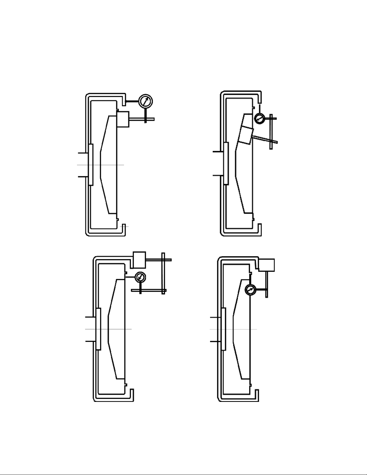
4.1.1 Flywheel to housing face runout check. (see Figure 3)
Mount the indicator base on the face of the flywheel and position the dial indicator tip
perpendicular to the flywheel housing mounting face. Rotate the flywheel 360 degrees while
holding pressure against the crankshaft thrust bearing.
SAE #1 Housing: 0.012 inches (0.305 mm)
SAE #1/2 Housing: 0.014 inches (0.356 mm)
SAE #0 Housing: 0.016 inches (0.406 mm)
SAE #00 Housing: 0.019 inches (0.483 mm)
4.1.2 Check flywheel housing bore runout. (see Figure 4)
Mount the indicator base on the face of the flywheel and position the dial indicator tip so its
movement is perpendicular to the pilot bore of the flywheel housing.
Rotate the flywheel through 360 degrees. The total indicator reading should not exceed:
SAE #1 Housing: 0.012 inches (0.305 mm)
SAE #1/2 Housing: 0.014 inches (0.356 mm)
SAE #0 Housing: 0.016 inches (0.406 mm)
SAE #00 Housing: 0.019 inches (0.438 mm)
4.1.3 Check flywheel face runout. (see Figure 5)
Mount the indicator base on the flywheel housing and position the dial indicator tip so that its
movement is perpendicular to the face of the flywheel. Position the indicator tip near the drive
ring mounting bolt circle diameter. Rotate the flywheel 360 degrees while holding pressure
against the crankshaft thrust bearing.

Page 5 of 18 WIM-CG-001_F
The total indicator reading should not exceed 0.011 inches (0.279 mm)
4.1.4 Check flywheel pilot bore runout. (see Figure 6)
Mount the indicator base on the flywheel housing and position the dial indicator tip so its
movement is perpendicular to the face of the flywheel. Rotate the flywheel through 360 degrees.
The total indicator reading should not exceed 0.005 inches (0.127 mm)
FIGURE 3 FIGURE 4
FIGURE 5 FIGURE 6
Other manuals for PTO
1
Table of contents
Other WPT POWER Industrial Equipment manuals