nVent.com/CADDY |4
1. Wire Rope Support Overview
C. SLK Features
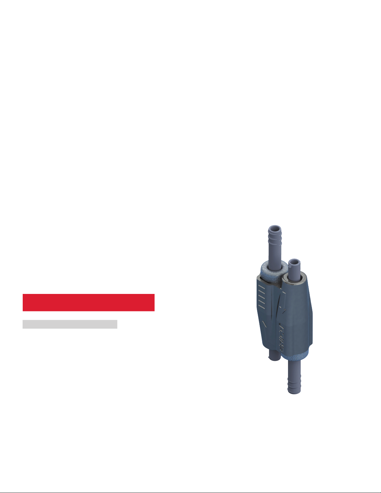
The locking device is the piece of hardware that holds the wire loop in place. The Speed Link SLK locking device is designed to be the
safest, most aesthetical, and easiest locking device on the market. The guide below shows several of the product’s innovative features
and the overall goal of each one.
EASE OF USE FEATURES
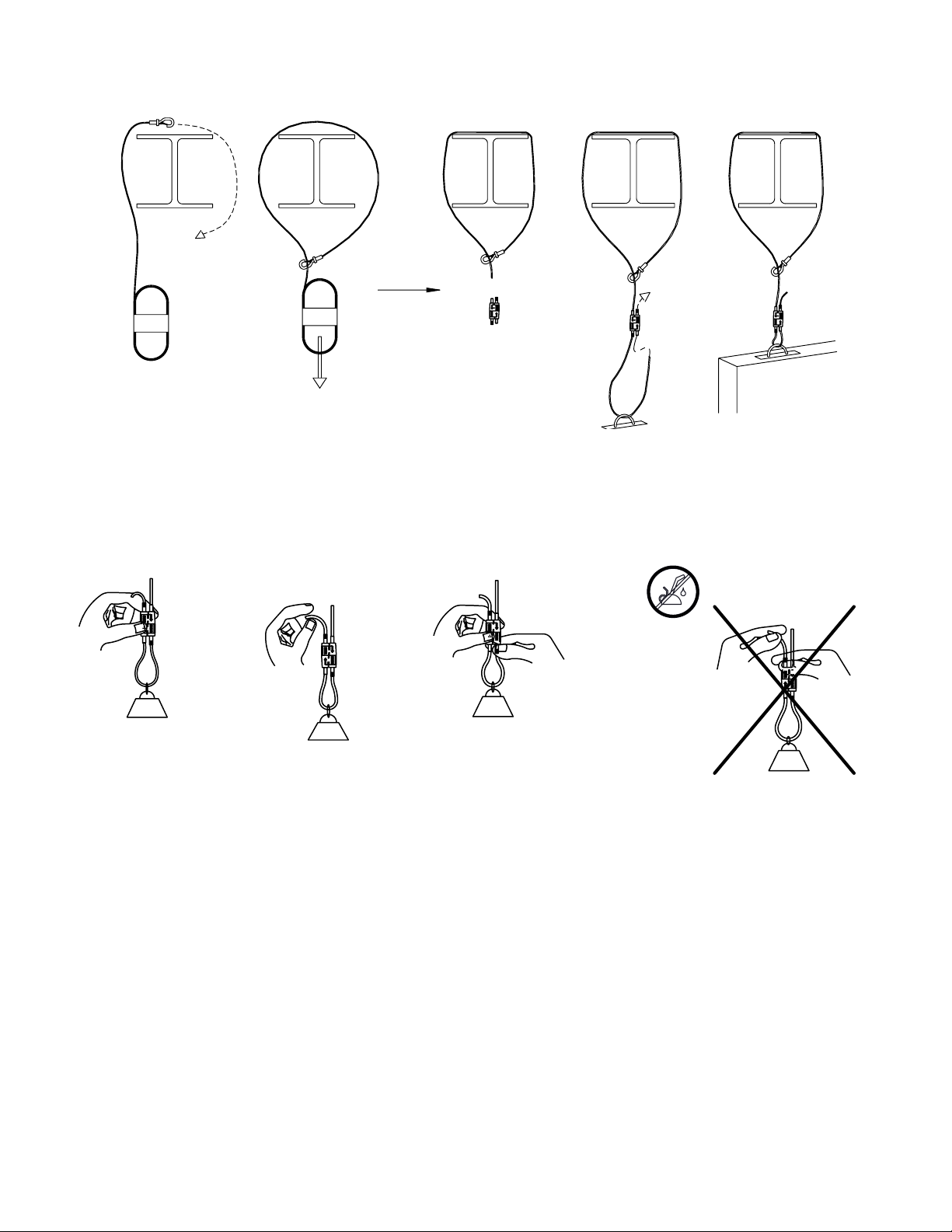
Arrows on the device clearly
demonstrate the correct direction
to push the wire
Speed Link is lighter, faster
to install, easier to transport
and generates less waste than
alternative hanging methods
Available in pre-cut lengths with
11 end-fittings or in bulk with
spools of wire to adapt to the
end-users’ needs and applications
Two tool-free locking devices are
available for three wire sizes
• SLK2 compatible with 1.5mm
and 2mm wire
• SLK3 compatible with 3mm wire
SAFETY FEATURES
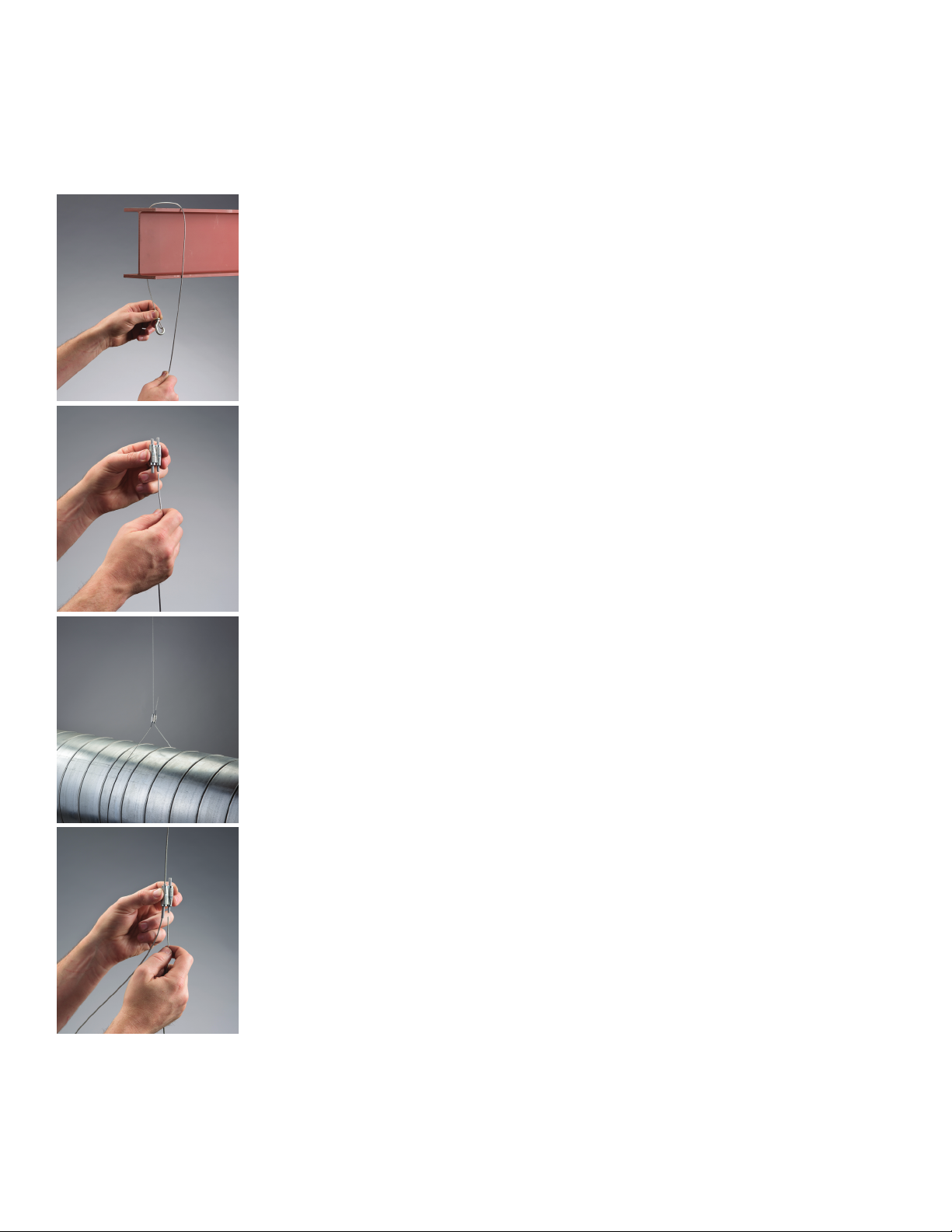
Keyless release tubes are
designed to allow safe and easy
adjustment, even while wearing
bulky gloves
Two jaws grip the wire inside
the device, holding the wire
more securely than single-cam
devices common among most
competitors. This rare gripping
mechanism allows it to be used
in unique applications such as
splicing / joining 2 wires, infinite
loop etc.
UL Listing on all 11 end-fittings
for pre-cut lengths, SMACNA
approved for Hook and Loop
end-fittings. Intertek Load Test
report available upon request.
AESTHETICAL FEATURES
Low-profile locking device
provides a positive aesthetic
to a finished project
The locking device can
accommodate wire rope at
up to 90 degrees, allowing
it to be positioned closer to
the load than other locking
devices on the market, hiding
it from view and creating
a much more aesthetically
pleasing installation.
The color of the line
corresponds to the larger
goal of each feature:
SAFETY FEATURES
AESTHETICAL FEATURES
EASE OF USE FEATURES