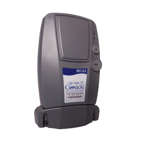
Conlog BEC21 User manual


Contents
Introduction ............................................................................................................................................................ 3
Disclaimer ............................................................................................................................................................... 3
Safety Information .................................................................................................................................................. 3
Safety and Maintenance Instructions ..................................................................................................................... 4
Installation .............................................................................................................................................................. 5
Diagrams and Illustrations.................................................................................................................................. 5
Procedure ............................................................................................................................................................... 6
Testing the Meter Installation and Sealing the Device ........................................................................................... 7
Cabling Specifications ............................................................................................................................................. 7
Display Messages .................................................................................................................................................... 8
Product Specifications ............................................................................................................................................ 9

Introduction
Congratulations on your new BEC21 electricity meter. This manual contains important information
on the installation. Please take time to read this manual to take full advantage of your meter’s many
benefits and features.
Warning and important safety instructions in this manual do not cover all possible conditions and
situations that may occur. It is your responsibility to use common sense, caution, and care when
installing, maintaining, and operating your meter.
Disclaimer
Electrical equipment should be installed, operated, serviced and maintained only by a qualified
installation electrician or an Electrical Contractor. No responsibility is assumed by Conlog (Pty) Ltd
for any consequences arising out of the use of this material. An installation electrician or electrical
contractor is one who has skills and knowledge related to the installation, and operation of the
electrical equipment has received safety training to recognize and avoid the hazards involved.
Safety Information
The following symbols are used to draw your attention to the relevant danger level, i.e. the severity
and probability of any danger, in the individual sections of this document.
Hazards or unsafe practices that may result in severe personal injury and/or property
damage.
Hazards or unsafe practices that may result in personal injury and/or property
damage.
Do NOT disassemble.
Follow directions explicitly.
Call the service Centre for help.
Note

Safety and Maintenance Instructions
Do not use product if physical or liquid damage is present. Contact your local supply
authority for assistance.
The wiring must be performed by a certified installation electrician and must conform to
the prevailing government standards and safety regulations.
This product is not a protection device and so requires the use of a suitable upstream
breaker e.g. 60A rated circuit upstream breaker.
When wiring the meter, ensure that the incoming supply is isolated by switching off the
upstream breaker.
We recommend that if you are connecting aluminium cables to this product, you use
bi-metal lugs.
Ensure that equipment is only accessible to an authorized and trained service person.
Ensure that the appropriate tools are used for the installation.
Ensure that the meter is installed in a dry location and is not exposed to water or
moisture
No sharp objects to be used to press the keypad. If keypad is damaged, please call
service technician.
There are no serviceable parts on the meter. Faulty meters must be returned to the
manufacturer for repairs. Only when these parts are fitted by the manufacturer can the
safety of the appliance can be guaranteed.
Cleaning of the meter must be done by a dry cloth.
Do not use liquids to wipe the meter as this may result in electrical shock.
Do not make any alterations to the appliance, Warranty will be void and safety of the
meter will be compromised.
Never open the casing/housing of the appliance. Tempering with electrical connections
or components and mechanical parts is highly dangerous and can cause operational
faults or electric shock.
Ensure product is disposed of, in accordance with local and national regulations.

Installation
Diagrams and Illustrations
Figure 2: Terminal Cover
Remove terminal screw before mounting the
meter and insert the terminal screw on to the
terminal cover.
Figure 1: Product Layout
Figure 3: Terminals
Figure 4: Mounting

Procedure
1. Before setting up the appliance, check it for any externally visible damage.
Under no circumstances should you use a damaged appliance. A damaged
appliance could be dangerous
2. Remove Terminal Tamper cover (Figure2)
3. Mark wall and drill mounting holes (Figure 4)
4. Mount meter on the wall and secure
5. Ensure upstream breaker is in the off position
6. Connect the incoming live supply to L LINE (Figure 3).
7. Connect the incoming neutral supply to N LINE (Figure 3)
8. Connect the outgoing live supply to L LOAD (Figure 3)
9. Connect the outgoing neutral supply to N LOAD (Figure 3)
10. Ensure that all terminal screws are securely tightened, all cables are securely
held in place and that no bare wiring is exposed
11. Secure the terminals & enclosure by threading steel wire through the security
holes and crimping (If required)
12. The meter must be installed on a solid flat surface with a 4mm screw
13. For indoor use only, can be installed in an enclosure or stand alone

Testing the Meter Installation and Sealing the Device
To test the installation:
1. Ensure that the Meter is correctly installed.
2. Apply power to the meter by closing the upstream breaker.
3. Check that the meter is displaying the available credit in kWh. If a zero balance is
displayed, a credit token needs to be purchased and entered into the meter using the
keypad.
4. Enter #100# on the keypad to view the meter serial number.
5. Compare the meter number displayed to the serial number printed on the meter label
and card, to confirm that the numbers match.
6. Turn on an appliance or light in the consumer's premises, to ensure that the consumer
has electricity. In some cases, meter commissioning may be required. For more
information, see the Commissioning the meter section
7. If the meter is working correctly, hand over the meter card and user guide to the
consumer.
Cabling Specifications
Cable
Size
Live wire
Max
16
mm
2
Neutral wire
Max
16
mm
2
Type
Copper
Wire insertion depth into terminal
block
12mm
Wire to be stripped with at least 12mm of
conductor contracting the terminals
Securing torque (cable onto terminal block)
2Nm

Display Messages
Reason for Abnormal Trip Condition
No Credit Available:
A credit token is
required to connect the supply
If the meter terminal cover is not fitted
correctly, the commissioning process
will not be accepted.
Flashing Bar Graph: Press #73# to
display trip condition
To Commission: Press #43# Load will
connect and tamper will activate.
Error
code Description
E01 Meter not initialised - contact Conlog
E02 Meter not calibrated - contact Conlog
E03 Internal error - contact Conlog
E04 No supply voltage present
E05 Reserved for future use
E06 Reserved for future use
E07 Communication error between the meter
and WCIU (Applicable to split meters only)
E08 Wireless user interface error - contact
Conlog (Applicable to split meters only)
E09 Incompatibility between the meter and
WCIU (Applicable to split meters only)
E10 Software error - contact Conlog
E12 Communication protocol error between
meter and WCIU (Applicable to split meters
only)
E20 Remote disconnection initiated

Product Specifications
Type
Meter Type
Static kWh meter
Meter Connection Type
Direct
Connected
Protection class
Class II, Double Insulation
Electrical Ratings
Nominal voltage (
-
20% +15%)
220V, 230V, 240V
Current Range
0.25
–
5(60)A
Max current (Imax)
60A
Utilisation category
UC2
Nominal power consumption
2W/10VA
Accuracy
Class 1
Supply frequency (±5%)
50Hz/60Hz
Impulse Withstand Voltage
CAT III
-
240V : 6kV
Environmental
Operating temperature
-
10 oC to +55 oC
Storage temperature
-
25
o
C to +70
o
C
Humidity
95% non
-
condensing
IP rating
IP54
Status indicators
Credit Status LED
Rate LED (1000 imp / kWh)
Terminals
Layout
Live
–
Neutral
-
Neutral
-
Load
Type
Cage clamp
Maximum size
16mm²
Interrogation
Type
Near Field Communication (NFC)
Compliance
Standards
IEC 62052
-
11 IEC 62055
-
52
IEC 62053
-
21 IEC 62055
-
21
SANS 1524
-
1 IEC 62055
-
31
SANS 15417 IEC 62055
-
41
ISO 9001 IEC 62055
-
51
ISO 14001
IEC 62052
-
31
Tel: +27 (31) 268-1111
Email: info@conlog.co.za Web: www.conlog.co.za
Conlog shall not be liable for any consequential loss of whatever nature and howsoever arising including, but
not limited to, loss arising from any defect in the product sold which is covered by Conlog’s warranty, or from
negligence on the part of Conlog, its directors, employees or agents. Conlog (Pty) Ltd Reg. No.
1982/011895/07
Part Number: 70 0102 702 000
Table of contents
Other Conlog Measuring Instrument manuals
Popular Measuring Instrument manuals by other brands

POSITECTOR
POSITECTOR 6000 quick guide

ATAGO
ATAGO RePo-1 instruction manual

MFJ
MFJ MFJ-836H instruction manual

FMC Technologies
FMC Technologies Proline Promass 83 E Description of Device Functions

Obvius
Obvius ModHopper R9120 Installation and operation manual

Phoenix Contact
Phoenix Contact EMpro EEM-MA371 Installation notes for electricians