Conrad Electronic FAZ 3000-SE-2 User manual

Version 01/07
FAZ 3000-SE-2
Radio controlled
activation switch
Item no. 75 03 38
OPERATING INSTRUCTIONS
This user manual belongs to this product. It contains important information
specific to its operation and handling. Please bear this in mind when
passing on the product to a third party.
Therefore keep this user manual for future reference!
A contents list can be found in the table of contents on page 2.
http://www.conrad.com
Imprint
These operating instructions are published by Conrad Electronic SE, Klaus-Conrad-
Str. 1, D-92240 Hirschau/Germany.
All rights reserved.
No reproduction (including translation) is permitted in whole or part e.g. photocopying,
microfilming or storage in electronic data processing equipment, without the express
written consent of the publisher.
The operating instructions reflect the current technical specifications at the time of
print. We reserve the right to change the technical or physical specifications.
© Copyright 2007 by Conrad Electronic SE. Printed in Germany.
100%
recycled
paper.
Bleached
without
chlorine.

2
Table of contents
Page
1. Introduction .......................................................................................... 3
2. Prescribed use ..................................................................................... 4
3. Scope of delivery ................................................................................ 4
4. Explanation of icons ............................................................................ 5
5. Safety instructions .............................................................................. 5
a) General information ....................................................................... 5
b) Batteries and rechargeable batteries ............................................ 6
6. Functionality ........................................................................................ 7
7. Opening the casing of the ‘FAZ 3000-SE-2’ ....................................... 8
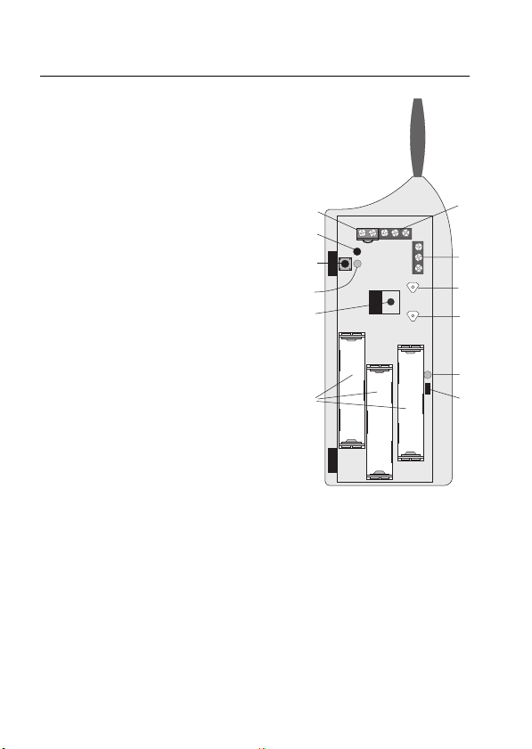
8. Connections and control elements ..................................................... 9
9. Installation with bolt switching contact ............................................. 10
a) General information ..................................................................... 10
b) Preparation ................................................................................... 11
c) Mounting and connection ............................................................. 12
d) Registering the ‘FAZ 3000-SE-2’ with the alarm base station ... 14
e) Operating the ‘FAZ 3000-SE-2 ’
(in combination with a bolt switching contact) ............................ 17
10. Operation using a key-operated switch/button ................................. 20
a) General information ..................................................................... 20
b) Preparation ................................................................................... 20
c) Mounting and connection ............................................................. 22
d) Registering the ‘FAZ 3000-SE-2’ with the alarm base station ... 24
e) Operating the ‘FAZ 3000-SE-2’
(in combination with a key switch/button) .................................. 27
11. Opening the casing of activation switch, replacing the batteries .... 30
12. Maintenance and cleaning ................................................................. 32
13. Disposal ............................................................................................. 32
a) General information ..................................................................... 32
b) Batteries and rechargeable batteries .......................................... 32
14. Information on the range ................................................................... 33
15. Technical specifications .................................................................... 34
16. Brief instructions ............................................................................... 35
a) Linking the activation switch to the alarm base station ............. 35
b) Opening the casing, replacing the batteries ............................... 35
17. Declaration of conformity (DOC) ..................................................... 35

3
1. Introduction
Dear customer,
Thank you for purchasing this product.
This product meets the requirements of both current national and
European guidelines.
In order to ensure continued fulfilment of legal requirements and safe operation
of this product, we kindly ask you to carefully follow the instructions in this
user manual!
Please read the user manual completely and observe the safety and operation
instructions before using the product!
All company and product names contained herein are trademarks of their
respective owners. All rights reserved.
Should you have any further questions, please contact our technical
service:
Germany: Tel. no.: +49 9604 / 40 88 80
Fax. no.: +49 9604 / 40 88 48
Email: [email protected]
Mon. to Thur. 8.00am to 4.30pm
Fri. 8.00am to 2.00pm

4
2. Prescribed use
The radio controlled activation switch ‘FAZ 3000-SE-2’ is only suitable for use
with the wireless alarm system ‘FAZ 3000’.
Connection points for external switches and buttons are found inside the
activation switch (for example, a bolt switching contact), with which the ‘FAZ
3000-Z’ alarm base station can be armed or disarmed.
The activation switch is equipped with an sabotage contact, which automati-
cally triggers a sabotage alarm via the alarm base station if the casing is opened
without authorisation.
Batteries must be used for the power supply.
The activation switch must only be mounted and used in dry indoor locations.
Make sure that the device does not get damp or wet!
Any use other than the one described above may damage the product and can
also increase the risk of short-circuit, fire, electric shock, etc.
No part of the product may be modified or adapted. The device may only be
operated when its casing is fully closed.
All the safety instructions and installation notes in this
manual must be observed without fail.
3. Scope of delivery
• ‘FAZ 3000-SE-2’ radio controlled activation switch
• Assembly material
• User manual

5
4. Explanation of icons
The icon with a lightning flash in a triangle is used to alert you to
potential personal injury hazards such as electric shock.
The icon with an exclamation mark in a triangle points to important
information in this user manual that must be observed.
The ‘hand’ symbol indicates special tips and information on
operation.
5. Safety instructions
The product’s guarantee becomes invalid, if the product is
damaged as a result of the failure to observe these operating
instructions! We do not assume any liability for any result-
ing damages!
We do not assume liability for damage to property or
personal injury caused by improper use or failure to observe
the safety instructions. In such cases the product’s guaran-
tee becomes invalid.
Dear customer, the following safety instructions are intended to protect
you as well as the device. Please take time to read through the following
points:
a) General information
• If you are not sure how to assemble, connect and install the device or if
you have doubts about its mode of operation, contact a skilled technician.
• For safety and licensing (CE) reasons any unauthorised alterations to and/
or modification of the product are not permitted.

6
• The product is only approved for installation and operation in dry and closed
indoor rooms. Make sure that the product does not get damp or wet.
• This product is not a toy and should be kept out of the reach of children.
• Do not leave packaging material lying around. This may become a
dangerous plaything in the hands of children.
• Handle the product with care; knocks, blows or even a fall from a low height
can damage it.
b) Batteries and rechargeable batteries
• Keep batteries/rechargeable batteries out of the reach of children.
• When inserting the batteries/rechargeable batteries make sure that the
polarity is correct.
• Do not leave batteries/rechargeable batteries lying around as they could
be swallowed by children or pets. In such case seek immediate medical care.
• Leaking or damaged batteries/rechargeable batteries may cause acid burns,
if they come into contact with skin. Therefore, please make sure you use
suitable protective gloves.
• Make sure that batteries/rechargeable batteries are not short-circuited or
thrown into a fire. They might explode!
• Never take batteries/rechargeable batteries apart!
• Conventional batteries must not be recharged. They might explode!
• If the device is not used for a longer period of time (for example, when
stored), remove the inserted batteries/rechargeable batteries to prevent
them from leaking and causing damage.
The activation switch may be powered using rechargeable batter-
ies. However, due to the lower voltage (rechargeable battery=
1.2V, battery = 1.5V) and the lower capacity, the period of
operation and the range are reduced. In some cases it will not be
possible to use rechargeable batteries, as the activation switch
continues to send a ‘battery empty’ signal, even when the
rechargeable cells are fully charged, thus triggering a disturbance
message.
Therefore, to ensure safe operation, only use high-quality alkaline
batteries.

7
6. Functionality
The radio controlled activation switch ‘FAZ 3000-SE-2’ is used to arm the ‘FAZ
3000-Z’ alarm base station via various switches/buttons.
This allows the alarm control centre to be activated or deactivated
simply by closing the entrance door – by means of a bolt switching
contact in the door’s strike plate – or via an external key switch.
One of the various following components can be connected to the ‘FAZ 3000-
SE-2’:
• Bolt switching contact (1 x on, contact on/off)
• Key switch (1 x turn; single-pole, change-over contact)
• Key button (1 x turn; single-pole, change-over contact)
The activation switch is equipped with an additional sabotage contact for the
connection of external key switches.
This can be connected with the sabotage contact on the key switch
casing. It then automatically triggers a sabotage alarm via the
alarm base station if the key switch’s casing is opened without
authorisation.
There is a further sabotage contact in the activation switch’s own casing. This
automatically triggers a sabotage alarm via the alarm base station if the
activation switch’s casing is opened without authorisation.
Two external light-emitting diodes (LEDs) may be connected to signal the
current status of the alarm base station (‘armed’ or ‘disarmed’). If these are,
for example, integrated into the casing of a key switch, the alarm base station’s
current status is immediately externally visible.

8
7. Opening the casing of the ‘FAZ-SE’
• Open the casing; the two casing halves are secured by two catches (‘A’ in
figure 1 below).
Using a flat-headed screw driver, carefully press the two catches about a
millimetre inwards, until you are able to open the casing:
First press one catch inwards and pull the casing approx. 1-2 millimetres
apart at this location. Then press the other catch inwards; the casing now
opens.
• The hole ‘B’ is used for mounting the device with screws. The two openings
marked ‘C’ are used to feed cable into the activation switch.
• The cables should be inserted before the
activation switch is mounted at the intended
installation location (see following page).
Two openings (‘C’) are found on the reverse
of the activation switch, through which the
cables should be fed inward.
When fastening the activation switch into
place, make sure the cables are not bent or
jammed.
Do not straighten any of the
components or additional
PCBs just so that it ‘looks
better’.
Figure 1
A
A
B
C
§
§

9
8. Connections and control elements
A‘KL1’ connection for the bolt switching
contact or switch/button
B‘KL2’ connection for two external LEDs to
indicate ‘armed’ or ‘disarmed’ status
C‘KL3’ connection for external sabotage
contact, for example, for the external cas-
ing of a key switch
(if this connection is used the jumper must
be removed!)
D‘TA1’ button for sabotage alarm, triggered
by opening the activation switch’s casing
E‘TA2’ button for manually switching to ‘ex-
ternally armed’, activated from outside
using a plastic stilo
F‘TA3’ button for manually switching to ‘inter-
nally armed’ or ‘disarmed’, activated from
outside using a plastic stilo
G‘D1’ LED, indicates radio transmission
H‘D2’ internal LED (red) for ‘armed’
I‘D3’ internal LED (green) for ‘disarmed’
JBore hole for mounting screw
K‘JP1’ jumper for selecting between ‘bolt
switching contact’ (jumper inserted) and
‘key switch/button’ (jumper removed)
LBattery compartment for three AAA batter-
ies
Figure 2
TA1
D3
D2
+
KL3 KL2
KL1
D1
TA3
TA2
JP1
A
B
C
D
E
F
G
H
I
J
K
L
D1
JP1
-
+
+
+
-
-

10
9. Installation with bolt switching contact
a) General information
The bolt switching contact must be mounted into the strike plate on the entrance
door.
When the door is locked (upon turning the key) the bolt switching
contact is closed, which causes the alarm system to be set to
‘externally armed’. When the door is unlocked, the contact opens
and automatically disarms the alarm system (‘disarmed’).
Bolt switching contacts are available as simple normally open contacts or as
change-over switches. Both versions can be used with the ‘FAZ 3000-SE-2’
activation switch, as only the normally open contact command is applied.
The bolt switching contact best suited to your entrance door should be available
from the door’s manufacturer.
Irrespective of what your case may be, the installation is best
entrusted to a specialist tradesperson in order to guarantee
problem-free functionality.
Alterations to the strike plate or door frame require corresponding expertise.
Amateur installation attempts can cause damage to the door opening
mechanism and the door frame, which may incur expensive repairs!
These are disproportional to the cost of a professional tradesperson, who also
gives a guarantee on any work carried out.

11
b) Preparation
• Lead the connection cable from the bolt switching contact to the installation
location selected for the activation switch. Lay the cables so that they are
not accessible from the outside. Lay the cables in-wall or in a suitable steel
tube.
In addition to the two cables required for the switch, a wire loop
could now also be laid to connect to the sabotage contact in the
activation switch.
If the cables are cut, the wire loop is then also interrupted and the
alarm base station triggers a sabotage alarm.
• Do not install the device in the immediate vicinity of large metal objects
(radiators, mirrors, aluminium laminated walls/insulating cladding, metal
doors) as this can reduce the wireless range.
• The activation switch should be installed in a dry indoor area (not in a damp
cellar or a bathroom, for example).
• Choose a secured area so that intruders cannot quickly tamper with the
device. The installation location should neither be immediately visible from
outside the house nor from within the house.
• There are two ways in which you can visually check the state of the alarm
system from the outside:
1. You can install the activation switch so that the two LEDs on the casing
of the activation switch are visible from the outside, through the glass
pane of a door, for instance. This, however, is contrary to the idea that
the installation location should not be immediately recognisable; see
above.
2. Inside the activation switch there is an option to connect two LEDs. When
a button is pressed these signal the state ‘disarmed’ or ‘externally armed’
in the same way the two LEDs on the casing do.

12
c) Mounting and connection
• If you intend to secure the activation switch with screws, you may need
to first drill a hole (6mm) and insert a suitable dowel.
When drilling or fastening screws be careful not to acciden-
tally damage any power supply lines, gas or water pipes as
this could pose a life-threatening danger!
By securing the activation switch with screws, you can prevent it from being
easily removed from the wall (sabotage protection).
• Before you screw the activation switch to the wall or mount it another way,
you should lead the cables inside the casing.
- Cable for the bolt switching contact
- Cable for external LEDs (if required)
- Cable for external sabotage contact (if required)
A cable duct is located on the back of the activation switch’s casing. Cable
can be lead from the left and from the right into device via this cable duct.
Cables enter the device from the mounting hole on the left or the right and
should then be lead through the hole in the circuit board to the screw terminal
strips.
• The jumper ‘JP1’ (K) must be inserted (see
figure 3, left).
• Attach the connection cable for the bolt
switching contact with the ‘KL1’ (A) terminal.
See figure 4.
With the bolt switching contact closed, both
contacts (above and middle contact) must
be connected.
KL1
Figure 3
Figure 4

13
Figure 5
Figure 6
KL2
Ro
t
Grün
• The LEDs are connected as shown in figure 5.
Make sure that you connect the red and green
LEDs correctly, so that they light up like the
LEDs that are already built-in.
Terminals from KL2:
Left connection: GND/earth
Middle connection: + for red LED
Right connection: + for green LED
Do not invert the polarity of the LED pins,
otherwise the respective LED will not light up.
Figure 6 shows you how to connect them
properly.
The shorter pin identifies the cathode (‘-’) and
the longer pin identifies the anode (‘+’).
Series resistors are already integrated onto
the circuit board of the activation switch,
which means that the LEDs can be connected
directly.
•Do not insert the batteries yet. The casing should remain open at first.
Green
Red

14
d) Registering the ‘FAZ 3000-SE-2’ with the alarm base
station
To register an activation switch the alarm base station must first
be set to receive radio signals. Make sure that you also read the
user manual of the ‘FAZ 3000-Z’ alarm base station.
Carry out the following steps on the ‘FAZ 3000-Z’ alarm base station:
Description of procedure Display on LCD
• The alarm base station must be in the top level. The
LCD should appear as on the right, for example,
with the time and the date.
• Briefly press the ‘Menü a/A’ button on the control
unit of the ‘FAZ-Z’ alarm base station.
• Use the ‘y’ and ‘z’ buttons to select the ‘sensorssensors
sensorssensors
sensors’
menu.
• Confirm your selection by briefly pressing the ‘OK’
button. ‘sensors addsensors add
sensors addsensors add
sensors add’ appears on the LCD.
• Press the ‘OK’ button again.
The ‘XX
XX
X’ character here stands for the number of
sensors that have already been registered plus
one.
• Keep pressing the ‘x’ button until the display shown
on the right appears on the LCD.
Now the alarm base station is ready to receive and the ‘FAZ 3000-
SE-2’ activation switch can be registered. A maximum of four of
the activation switches can be registered with the alarm base
station.
sensors
disarm
16:30 14.12
troubles
sensors
add
sensor X
clear
rem. sw. 1
clear

15
• Now go to the activation switch that you wish to register with the alarm base
station.
After installing the activation switch the casing of the device is
still open, the batteries are not yet inserted.
• Insert 3 AAA batteries, making sure that
the polarity is correct. See figure 7.
• The activation switch contacts the alarm
base station by sending a radio signal.
The red LED on the activation switch
briefly lights up, and the alarm base
station emits a short signal tone to con-
firm signal reception.
• Close the casing of the activation switch,
so that the two locking hooks audibly click
in.
Figure 7
TA1
D3
D2
+
KL3 KL2
KL1
D1
TA3
TA2
JP1
D1
JP1
+
-
+
-
+
-

16
• Return to the alarm base station. The LCD’s
display has changed. See the figure on the right.
Here, ‘11
11
1’ is the number of the activation switch
(a maximum of four are possible).
• Use the buttons on the alarm base station to enter
the name of the activation switch, for example
‘Main doorMain door
Main doorMain door
Main door’.
fTo enter the letters use the 2-9 buttons, each
of which represents several letters (click
through as with a mobile phone by repeat-
edly and quickly pressing the same button).
fNumbers and umlauts can also be found on
the buttons.
fUse the ‘0’ button to enter a space character.
fSpecial characters can be entered using the
‘y’ and ‘z’ buttons.
fYou can use the ‘Menü a/A’ button to switch
between lower and upper case.
fThe cursor automatically jumps to the next
position approx. one second after the last
button was pressed.
fYou can use the ‘wC’ button to delete a
character you entered incorrectly by mis-
take.
• By pressing the ‘OK’ button, you are now able to
register the next activation switch.
• Press the ‘wC’ button three times to exit the alarm
base station’s registration mode. You are in the
normal display mode again (top level) of the
alarm base station.
rem. sw. 1
_
rem. sw. 1
Main door
rem. sw. 2
clear
disarm
16:40 14.12

17
e) Operating the ‘FAZ 3000-SE-2’
(in combination with a bolt switching contact)
The ‘FAZ 3000-SE-2’ activation switch has two buttons and two LEDs:
• Button ‘int. armed / disarmed’
• Button ‘ext. armed’
• Red LED ‘armed’
• Green LED ‘disarmed’
Description of the ‘int. armed / disarmed’ button
Using the ‘int. armed / disarmed’ button you can alternately change the state
of the alarm system to deactivated or internally activated.
• During normal operation both of the LEDs are switched off, so that a potential
burglar is not forewarned of the current state of the alarm system.
• Briefly press the ‘int. armed / disarmed’ button once. Green ‘disarmed’ LED
lights up (it goes out after approx. 30 seconds).
• Press the ‘int. armed / disarmed’ button again.
If a magnet contact is not closed (for example, a window is open)
or if the bolt switching contact is open (for example, the front door
is not locked) the system will refuse to arm when the button is first
pressed; the alarm base station remains ‘disarmed’.
The activation switch also refuses to activate the alarm system
when the ‘int. armed / disarmed’ button is pressed for the first time,
if there is a fault (a sensor’s battery is empty, a sabotage contact
is open, the alarm base station’s LCD displays ‘alarm’ and so on).
The green LED lights up for 30 seconds and the red LED blinks.
The state is not switched to ‘internally armed’.
Only pressing the ‘int. armed / disarmed’ button for a second time
forces the alarm system to switch to be ‘internally armed’.
• The alarm base station emits a short signal tone as confirmation and
switches to the ‘internally armed’ state. The red ‘armed’ LED on the ‘FAZ
3000-SE-2’ lights up for approx. 30 seconds and then goes out again.

18
To switch the state of an alarm base station from ‘internally armed’
to ‘disarmed’, briefly press the ‘int. armed / disarmed’ button on
the ‘FAZ 3000-SE-2’ activation switch. The red ‘armed’ LED briefly
lights up. Afterwards the green ‘int. armed/ disarmed’ LED lights
up for approx. 30 seconds.
Of course you can also use the ‘disarmed’ button on the alarm
base station or a ‘FAZ 3000-FB’ remote control to switch the alarm
base station to ‘disarmed’!
Opening the bolt switching contact always switches the
alarm base station status to ‘disarmed’.
Example: A person returning home at night and unlocking the entrance door
automatically deactivates the ‘internally armed’ alarm base station, the
alarm base station is then ‘disarmed’.
Description of the ‘ext. armed’ button
The button ‘ext. armed’ switches the alarm base station and the bolt switching
contact to ‘externally armed’ mode. To do so, proceed as follows:
• The alarm base station is ‘disarmed’, both activation switch LEDs are off,
the bolt switching contact is open (the entrance door is not locked).
• Before leaving the house the ‘ext. armed’ button on the activation switch
must be pressed once briefly. The ‘armed’ LED lights up for 30 seconds.
• The bolt switching contact must be closed within these 30 seconds (by
leaving the house and locking the entrance door) so that the alarm base
station switches to ‘externally armed’. The alarm base station confirms its
armed status with a brief signal tone, the red ‘armed’ LED on the activation
switch lights up and then goes out again 30 seconds later.
If a magnet contact is not closed (for example, because a window
is open) the alarm base station will not arm when the bolt switching
contact is closed (upon locking the entrance door); the alarm base
station remains ‘disarmed’!
Only opening and closing the bolt switching contact again (unlocking and
relocking the door) within the 30 second count-down will force the alarm base
station into the ‘externally armed’ mode, even though a window magnet
contact is open, for example.

19
Similarly, in case of a fault (sensor battery empty, sabotage contact open,
‘alarm’ appears on the alarm base station’s LCD, etc.) the activation switch
will refuse to arm when the bolt switching contact is first closed.
This is indicated as soon as the ‘ext. armed’ button is pressed:
The green LED lights up for 30 seconds and the red LED blinks.
Closing the bolt switching contact (locking the entrance door) has
no effect and the alarm base station remains ‘disarmed’.
Only opening and closing the bolt switching contact again (unlocking and
relocking the door) within the 30 second count-down will force the alarm base
station into the ‘externally armed’ status, even though a fault is registered
(sabotage contact on a sensor is open, battery empty, etc.).
• For safety reasons you should not force the alarm base station to switch
to the ‘externally armed’ mode. Instead you should determine the cause of
the error on the alarm base station (look at the LCD, call up the ‘troublestroubles
troublestroubles
troubles’
menu and check the sensors) and then remove it!
If a bolt switching contact is open (door is not locked) the alarm
base station’s display reads ‘cont. opencont. open
cont. opencont. open
cont. open’ (contact open).
The ‘troublestroubles
troublestroubles
troubles’ menu of the alarm base station indicates which activation
switch or sensor has triggered a ‘fault’.
Though this can lead to confusion, it is in fact an additional security feature
if more than one door is equipped with a bolt switching contact and activation
switch.
Opening the bolt switching contact always switches the
alarm system to ‘disarmed’.
Example: A person returning home and unlocking the entrance door
automatically deactivates the ‘externally armed’ alarm base station, the
alarm base station is then ‘disarmed’.

20
10. Operation using a key-operated switch/
button
a) General information
A key switch or key button may be installed outside next to the entrance door
and allows the alarm base station to be armed (‘externally armed’) and disarmed
from outside.
The key switch or button must be equipped with a change-over switch or button
(‘1 x turn’).
b) Preparation
• Lead the connection cable from the key switch/button casing to the
installation location selected for the activation switch. Lay the cables so
that they are not accessible from the outside. Lay the cables in-wall or in
a suitable steel tube.
In addition to the three cables required by the key switch/button,
two further cables can be laid for the sabotage contact (if one is
included in the casing of the key switch/button).
If the key switch/button casing is opened without authorisation,
the alarm base station automatically triggers a sabotage alarm
(regardless of the current status of the alarm base station).
If you wish to install two light-emitting diodes (LEDs) in the key switch/button
casing to indicate the status of the activation switch or alarm base station,
another three (in the case of a shared earthing cable for both LEDs) or four
cables must be laid.
You will therefore require a cable with 8 or 9 wires if you wish to take
advantage of all options.
• The activation switch should not be installed in the immediate vicinity of
large metal objects (radiators, mirrors, aluminium-coated walls/insulation
panelling, metal doors), as this will reduce the wireless range.
Table of contents
Other Conrad Electronic Switch manuals
Popular Switch manuals by other brands

D-Link
D-Link DKVM-222 user manual

ZyXEL Communications
ZyXEL Communications XGS1010-12 quick start guide

Extreme Networks
Extreme Networks BlackDiamond X8 Series datasheet

HP
HP zl user guide

Ruijie
Ruijie RG-ES05 Series Quick installation guide

Cisco
Cisco 6500 - Catalyst Series 10 Gigabit EN Interface Module... Command reference