Conrad Electronic KAPILLAR User manual

Thermostat
KAPILLAR Seite 3 - 9
Thermostat
KAPILLAR Page 10 - 15
Thermostat
KAPILLAR Page 16 - 23
Thermostaat
KAPILLAR Pagina 24 - 30
Best.-Nr. / Item-No. / Node commande / Bestnr.: 62 18 70
BEDIENUNGSANLEITUNG OPERATING INSTRUCTIONS
NOTICE D’EMLPOI GEBRUIKSAANWIJZING
Version 11/06

Diese Bedienungsanleitung gehört zu diesem Produkt. Sie ent-
hält wichtige Hinweise zur Inbetriebnahme und Handhabung.
Achten Sie hierauf, auch wenn Sie dieses Produkt an Dritte wei-
tergeben.
Heben Sie deshalb diese Bedienungsanleitung zum Nachlesen auf!
These Operating Instructions accompany this product. They
contain important information on setting up and it. You should
refer to these instructions, even if you are buying this product
for someone else.
Please retain these Operating Instructions for future use!
Le présent mode d'emploi fait partie intégrante du produit. Il
comporte des directives importantes pour la mise en service et
la manipulation de l'appareil. Tenir compte de ces remarques,
même en cas de transfert du produit à un tiers.
Conserver ce mode d'emploi afin de pouvoir le consulter à tout
moment.
Deze gebruiksaanwijzing hoort bij dit product. Zij bevat belan-
grijke informatie over de inbedrijfstelling en het gebruik. Let
hierop, ook wanneer u dit product aan derden overhandigt.
Bewaar daarom deze gebruiksaanwijzing om in voorkomende geval-
len te kunnen raadplegen.
2

Einführung
Sehr geehrter Kunde,
wir bedanken uns für den Kauf des Thermostates.
Mit diesem Produkt haben Sie ein Gerät erworben, welches nach
dem heutigen Stand der Technik gebaut wurde. Um diesen Zustand
zu erhalten und einen gefahrlosen Betrieb sicherzustellen müssen
Sie als Anwender diese Bedienungsanleitung beachten!
Bei Fragen wenden Sie sich an unsere Technische Beratung
Deutschland: Tel.-Nr.: 0180/5 31 21 11
Fax-Nr.: 09604/40 88 48
e-mail: [email protected]
Mo. - Fr. 8.00 bis 18.00 Uhr
Österreich: Tel.-Nr.: 0 72 42/20 30 60
Fax-Nr.: 0 72 42/20 30 66
e-mail: [email protected]
Mo. - Do. 8.00 bis 17.00 Uhr, Fr. 8.00 bis 14.00 Uhr
Schweiz: Tel.-Nr.: 0848/80 12 88
Fax-Nr.: 0848/80 12 89
e-mail: [email protected]
Mo. - Fr. 8.00 bis 12.00 Uhr, 13.00 bis 17.00 Uhr
Bestimmungsgemäße Verwendung
Das Thermostat Kapillar findet seinen Einsatz als einstellbarer Ther-
mostat für Klima- oder Lüftungsanlagen bzw. als Ersatzthermostat
für Kühl- und/oder Gefriergeräte im Temperaturbereich von -35°C
bis +35°C.
Das Thermostat ist für einen Anschluß an 230 VAC zugelassen. Der
Maximale Schaltstrom beträgt 16 A ohmsche Last und 4 A induktive
Last.
3

Eine Verwendung ist nur in trockenen geschlossenen Räumen, also
nicht im Freien erlaubt. Der Kontakt mit Feuchtigkeit ist zu vermeiden.
Eine andere Verwendung als zuvor beschrieben führt zur
Beschädigung dieses Produkts. Darüber hinaus ist dies mit
Gefahren, wie z.B. Kurzschluß, Brand, elektrischer Schlag, etc.
verbunden. Das gesamte Produkt darf nicht geöffnet, geändert,
bzw. umgebaut werden!
Sicherheitshinweise
Bei Schäden, die durch Nichtbeachten der Anleitung
verursacht werden, erlischt der Garantieanspruch!
Für Folgeschäden, die daraus resultieren, überneh-
men wir keine Haftung!
Bei Sach- oder Personenschäden, die durch
unsachgemäße Handhabung oder Nichtbeachtung
der Sicherheitshinweise verursacht werden, über-
nehmen wir keine Haftung. In solchen Fällen erlischt
jeder Garantieanspruch.
Aus Sicherheits- und Zulassungsgründen ist das eigenmächtige
Umbauen und/oder Verändern des Thermostaten verboten.
Die Installation des Raumthermostaten darf nur durch eine Fach-
kraft durchgeführt werden, welche mit den einschlägigen Installa-
tions- und Einbauvorschriften vertraut ist.
Es ist darauf zu achten, daß die Leitungsisolierung der Anschlußlei-
tung(en) nicht beschädigt wird, da bei Berührung der blanken Leiter
Lebensgefahr besteht.
Der Thermostat ist nicht für die Außenmontage geeignet und darf
somit nur innen bzw. in Geräten (Gehäusen) angeschlossen und
betrieben werden.
4

Beim Öffnen von Abdeckungen oder Entfernen von Teilen, außer
wenn dies von Hand (ohne Werkzeug) möglich ist, können span-
nungsführende Teile freigelegt werden. Auch können Anschlußstel-
len spannungsführend sein. Vor einer Wartung, ein Instandsetzung
oder einem Austausch von Teilen muß das Gerät von allen Span-
nungsquellen getrennt sein.
Kondensatoren im Gerät (Anlaufkondensator vom Kompressor)
können noch geladen sein, selbst wenn das Gerät von allen Span-
nungsquellen getrennt wurde.
Es ist sicherzustellen, daß die zugelassene Anschlußleistung nicht
überschritten wird. Sie beträgt beim Thermostat: 230 VAC / 50 Hz.
Max. 16 (4) A.
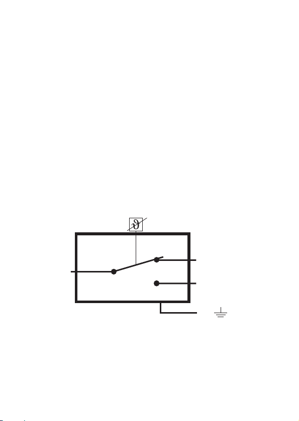
Beachten Sie unbedingt, daß der Schutzleiter (grün/gelb) an den
dafür vorgesehenen Kontaktzungen mit angeschlossen wird. Bei
unterbrochenem/nicht angeschlossenem Schutzleiter besteht im
Fehlerfall an berührbaren leitfähigen Teilen Lebensgefahr durch vor-
handene Netzspannung!
Beachten Sie weiterhin, daß das Fühlerröhrchen (Kapillar) nicht
gequetscht bzw. zu eng gebogen wird => Bruchgefahr. Bei einem
geöffneten/gebrochenen Fühlerröhrchen ist der Thermostat nicht
mehr einsetzbar.
Wenn anzunehmen ist, daß ein gefahrloser Betrieb nicht mehr mög-
lich ist, so ist das Gerät außer Betrieb zu setzen und gegen unbeab-
sichtigten Betrieb zu sichern. Es ist anzunehmen, daß ein gefahrloser
Betrieb nicht mehr möglich ist, wenn
- das Gerät sichtbare Beschädigungen aufweist,
- das Gerät nicht mehr arbeitet, und
- nach längerer Lagerung unter ungünstigen Verhältnissen,
- oder nach schweren Transportbeanspruchungen.
Setzen Sie das Gerät keinen hohen Temperaturen, Feuchtigkeit oder
starken Vibrationen, sowie keiner mechanischer Belastung aus.
5

In gewerblichen Einrichtungen sind die Unfallverhütungsvorschriften
des Verbandes der gewerblichen Berufsgenossenschaften für elek-
trische Anlagen und Betriebsmittel zu beachten.
Produktbeschreibung
Der Thermostat ist mit seinem einstellbaren Temperaturbereich von
-35°C bis +35°C hauptsächlich als Ersatzthermostat für Kühlschränke
oder -truhen und/oder für Gefrierschränke oder -truhen gedacht.
Aber auch ein Einsatz in Klima- oder Lüftungsanlagen wäre denkbar.
Im nicht elektrischen Kapillarröhrchen (Fühler), fest mit dem Ther-
mostat verbunden, befindet sich ein Mittel, welches sich bei Erwär-
mung (z.B. beim Öffnen der Kühlschranktür ) ausdehnt. Am Ende des
„Fühlers“ befindet sich eine sog. Druckdose, die über die „Einstel-
lachse“ mechanisch vorgespannt wird (wie bei einem Bi-Metallschal-
ter im Bügeleisen). Bei Erwärmung dehnt sich das Mittel im Röhrchen
aus und betätigt über ein Stellglied den Schaltkontakt. Der Stromkreis
wird daraufhin geschlossen, der Kühlkompressor (oder Absorber), mit
nicht mehr als max. 16(4) A Stromaufnahme, läuft an. Der Stromkreis
ist solange geschlossen (eingeschaltet), bis die eingestellte Tempera-
tur am Kapillarröhrchen unterschritten wird. Der Stromkreis kann aber
auch durch den Drehschalter von Hand unterbrochen werden.
Der Schaltausgang wird mit dem Kühlkompressor in Reihe verbun-
den. Das Gerät ist für den Gehäuseeinbau ausgelegt. Lesen Sie
jedoch vor dem Anschluß des Thermostaten bzw. vor der Erstinbe-
triebnahme unbedingt die Sicherheitsweise sorgfältig durch.
Lieferumfang:
• Thermostat komplett mit Fühler
• deutsche Bedienungsanleitung
6

Inbetriebnahme
Vor Inbetriebnahme sind sowohl der bestimmungs-
gemäße Verwendungszweck, als auch die Sicher-
heitshinweise und technischen Daten zu beachten.
Stellen Sie vor Inbetriebnahme sicher, daß das Gerät
für den Anwendungszweck, für den es eingesetzt
werden soll geeignet ist.
Vor der Installation des Thermostaten ist der Haupt-
schalter vom Hausnetz (FI) auszuschalten, bzw. das
Gerät (Kältemaschine, in welches das Thermostat
eingebaut werden soll), vom Netz zu trennen (aus-
stecken).
Anschluß
Das Thermostat ist mit einem einpoligen Umschalter (Wechselkon-
takt) ausgestattet. Die Belegung entnehmen Sie der Zeichnung. Bei
Schutzklasse I Geräten muss in jedem Falle der Schutzleiter (PE)
angeschlossen werden.
P1
1
2
PE
7

Aufgrund der Vielzahl von Geräten und Einsatzmöglichkeiten,
kann kein genereller Anschluss angegeben werden. Bitte
beachten Sie die Kontaktbelegung.
Hinweis zu Anschlußdaten!
Der eingebaute Schaltkontakt ist für eine Schaltspannung von
400VAC ausgelegt, zugelassen ist das Thermostat jedoch für eine
Schaltspannung von max. 230 VAC. Der max. Schaltstrom beträgt
16 A ohmsche Last und 4 A induktive Last (frühe Bezeichnung
„Motorlast“).
Montage
Das Einstellelement am Thermostat ist mit einem 10-mm-Gewinde-
stutzen (metrisch, Linksgewinde) mit einer Gewindehöhe von ca.
5 mm versehen. Beachten Sie beim Einbau in ein Gerät (z.B. Kühl-
schrank) die Gehäusematerialstärke, um eine sichere Befestigung
mittels einer Befestigungsmutter (mindestens 2 „Gewindegänge“)
zu gewährleisten. Der Kapillarfühler muß möglichst großflächig zwi-
schen den Kühlschlangen verlegt werden. Achten Sie jedoch unbe-
dingt darauf, daß der Biegeradius nicht zu klein wird, um das Kapil-
larsystem nicht zu beschädigen. Die Länge der Kapillarröhrchen
darf auf keinen Fall gekürzt werden.
Einstellung / Abschaltung
Nach erfolgtem Einbau und Anschluß muß ein Einstellrad (nicht im
Lieferumfang enthalten) befestigt werden. Verwenden Sie am
besten eine Skala von „min“ bis „max“. Drehen Sie die Einstellachse
auf Linksanschag, schaltet das Thermostat bei ca. -35C. Drehen Sie
die Einstellachse auf Rechtsanschlag, schaltet das Thermostat bei
ca. +35°C. Eine Aus-Stellung ist nicht vorhanden.
8

Entsorgung
Entsorgen Sie das unbrauchbar gewordene Thermostat gemäß den
geltenden gesetzlichen Vorschriften.
Technische Daten
Betriebsspannung ...........: Zugelassen auf 230 VAC 50 Hz
Kontaktbelastbarkeit .......: Max. 16 A ohmsche Last
Max. 4A induktive Last
Regelbereich ...................: -35°C bis +35°C, stufenlos
Abmessungen (L x B x H): ca. 54 x 36 x 51 mm
(mit Achse, ohne Fühler)
Fühlerlänge......................: ca. 150 cm („gestreckt“)
Anschlüsse ......................: 6,3mm Steckkontakte
9

Introduction
Dear customer,
Thank you for purchasing the thermostat.
With this device, you have purchased a product designed in accor-
dance with the latest state of the art. To maintain this status and to
ensure risk-free operation, you, as the user, must comply with these
operating instructions.
For a fast response of your technical enquiries please use the email
address listed below.
Germany: Fon. + 49 9604/40 88 80
Fax + 49 9604/40 88 48
e-mail: [email protected]
Mon to Thurs 8.00am to 4.30pm
Fri 8.00am to 2.00pm
Intended use
The adjustable Kapillar thermostat is intended for application in air
conditioning or ventilation systems or as a spare thermostat for
coolers or freezers in a temperature range from -35°C to +35°C.
The thermostat is approved for connection to 230 VAC. The maxi-
mum switching current is 16 A resistive load and 4 A inductive load.
It may only be used indoors; never outdoors. Contact with moisture
must be avoided at all times.
Use other than that described above will lead to damage to the
product. In addition, this may lead to hazards such as short cir-
cuits or fire. The product as a whole may not be opened, modi-
fied or reconstructed.
10

Safety instructions
Damage due to non-compliance with these instruc-
tions renders the warranty void. We accept no liability
for consequential damage resulting from failure to
comply with these operating instructions.
We do not accept any liability for damage to property
or injury to persons caused by the mishandling of the
device or non-compliance with the safety instruc-
tions. The warranty will be rendered null and void in
such cases.
For safety and licensing (CE) reasons, unauthorised conversion
and/or modifications to the thermostat are not permitted.
Only an expert familiar with the pertinent installation assembly
instructions may install the room thermostat.
Make sure that the cable insulation is not damaged; touching blank
wires may lead to a mortal electric shock.
The thermostat is not suited for outdoor installation and may only be
installed and operated indoors or inside devices (casing).
Live components may be exposed if covers are opened or parts are
removed unless this can be done by hand without using tools.
Connection points may also be live. If the appliance needs to be
serviced or repaired or if parts or assemblies must be replaced, the
appliance must be disconnected from all voltage sources first.
Capacitors inside the device (start-up capacitator of the compressor)
may still be charged, even if the device has been disconnected from
all voltage sources.
Ensure that the admissible connection current is not exceeded. For
the thermostat, this is: 230 VAC / 50 Hz. max. 16 (4) A.
11

You have to make sure that the protective conductor (green/yellow)
is connected to the provided contact latches. In case of an interrup-
ted/not connected protective conductor, touching live parts may
result in a mortal electric shock due to the mains voltage.
Also make sure that the capillary is not crimped or bent too tight =>
danger of breaking. If the capillary is open/broken, the thermostat
can no longer be used.
If you have reasons to assume that the safe operation is not possi-
ble any longer, take the device out of operation immediately and
protect it against inadvertent operation. It must be assumed that
safe operation is no longer possible, if
- The device shows signs of visible damage,
- The device no longer functions and
- the device has been stored under unfavourable conditions for
a longer period of time
- the device has been subjected to unsuitable conditions of
transport
Do not expose the device to high temperatures, dampness or
strong vibration or excessive mechanical loads.
The accident prevention regulations of the relevant trade associations
for electrical systems and operating materials are to be observed in
commercial institutions.
Product description
The thermostat with its adjustable temperature range from -35°C to
+35°C is mainly intended as a replacement thermostat for refrigera-
tors and freezers. It can also be applied in air conditioning or venti-
lation systems.
12

There is a medium in the non-electric capillary (sensor), which is per-
manently connected to the thermostat. This medium expands at war-
ming (e.g. opening the refrigerator door). At the end of the sensor is a
so-called barometric cell, which is mechanically pre-stressed via the
free flexible axle (like with a bi-metal switch in irons). At warming, the
medium in the capillary expands and triggers the switching contact
via an adjustment joint. This closes the circuit and the cooler com-
pressor (or absorber) with a power consumption of max. 16(4) A
starts. The circuit remains closed (activated) until the set temperature
on the capillary is undercut. The circuit can also be interrupted
manually via the rotary switch.
The switching output is connected in series with the cooler compres-
sor. The device is designed for installation in a casing. You must read
the safety notices prior to connecting and commissioning the ther-
mostat.
Scope of Delivery
• Thermostat with sensor
• English operating instructions
Initial operation
Before starting up operation, both the intended pur-
pose of use and the safety instructions and techni-
cal data are to be observed! Make sure before com-
missioning that the device is suitable for the
intended purpose.
Prior to the installation of the thermostat, you must
turn off the mains switch (Fl) and/or separate the
device (cooler into which the thermostat is to be
installed) from the mains voltage (unplug).
13

Connection
The thermostat is equipped with a single-pole switch (changeover
contact). For the assignment, refer to the drawing. The protective
conductor (PE) must be connected with Protection Class I devices.
General connection instructions cannot be provided due to the
large number of devices and application purposes. Please
observe the contact assignment.
Notice on connection data!
The integrated switching contact is designed for a switching voltage of
400VAC, but the thermostat is only approved for a switching voltage
of max. 230 VAC. The maximum switching current is 16 A resistive
load and 4 A inductive load.
Mounting
The adjustment element on the thermostat is equipped with a 10-mm
thread (metric, left-handed thread) with a thread height of approx.
5 mm. When installing it in a device (e.g. refrigerator), observe the
P1
1
2
PE
14

casing material thickness to ensure safe attachment with an attach-
ment nut (at least 2 threads). The capillary sensor must be installed
broadly between the cooling coils. Make sure that the bending radius
is not too small to prevent damage to the capillary system. The length
of the capillaries may not be shortened under any circumstances.
Adjustment / Off
After installation and connection, you have to attach an adjustment
wheel (not included in the delivery). You best use a „min“ to „max“
scale. If you turn the adjustment axis to the left, the thermostat trig-
gers at approx. -35°C. If you turn the adjustment axis to the right,
the thermostat triggers at approx. +35°C. There is no off position.
Disposal
Once the thermostat becomes unusable, dispose of it in accordance
with the relevant statutory regulations.
Technical data
Operating voltage............: Approved for 230 VAC 50 Hz
Contact load....................: Max. 16 A resistive load
Max. 4A inductive load
Control range...................: -35°C to +35°C, continuous
Dimensions (L x W x H) ...: ca. 54 x 36 x 51 mm
(with axis, without sensor)
Sensor length ..................: ca. 150 cm (stretched)
Connections ....................: 6.3mm plug contacts
15

Introduction
Cher client,
Nous vous remercions d'avoir fait l'acquisition de ce thermostat.
Vous possédez à présent un système qui bénéficie des derniers
progrès de la technique moderne.
Pour ne pas compromettre cet état et permettre un fonctionnement
optimal, il importe que l'utilisateur se conforme aux consignes de
sécurité et aux avertissements énoncés dans ce mode d'emploi.
Pour toutes questions, adressez vous à notre service conseil technique
France: Tél. 0 892 897 777
Fax 0 892 896 002
e-mail: [email protected]
du lundi au vendredi de 8h00 à 18h00
le samedi de 8h00 à 12h00
Suisse: Tél. 0848/80 12 88
Fax 0848/80 12 89
e-mail: [email protected]
du lundi au vendredi de 8h00 à 12h00,13h00 à 17h00
Utilisation conforme
Ce thermostat Kapillar a été conçu pour une utilisation en tant que
thermostat réglable pour climatisation ainsi qu'en tant que thermostat
de remplacement pour réfrigérateur à une gamme de température de
-35°C à +35°C.
Ce thermostat doit être alimenté par le réseau électrique de 230 VAC.
Il supporte un courant alternatif maximale de 16 A de charge ohmique
et de 4 A de charge inductive.
Il a été conçu exclusivement pour une utilisation dans locaux secs
et fermés et non à l'extérieur.
16

Une utilisation différente de celle décrite dans cette notice est
interdite et entraîne des dommages sur le produit. De plus, vous
vous exposez à des risques tels que : court-circuit, incendie,
choc électrique, etc. L'ensemble du produit ne doit être ni
démonté, ni modifié.
Consignes de sécurité
La garantie ne couvre pas les dommages ayant pour
cause la non-observation des instructions contenues
dans cette notice. Nous déclinons toute responsabilité
pour les dommages qui en résulteraient directement
ou indirectement.
Les dommages matériels et corporels résultent d'une
mauvaise utilisation ou de la non-observation des
consignes de sécurité ne peuvent en aucun cas
engager notre responsabilité. De tels cas entraînent
l'annulation de la garantie.
Pour des raisons de sécurité et de conformité (CE), il est interdit de
démonter et/ou de modifier soi-même l'appareil.
L'installation de ce thermostat est exclusivement réservée à un per-
sonnel qualifié.
Veillez à ce que l'isolation des câbles d'alimentation ne soit pas
détériorée étant donné qu'il existe un contact des fils. Danger de
mort.
Le thermostat n'est pas conçu pour un montage extérieur et ne peut
être ainsi alimenté et branché à l'intérieur d'appareils, par exemple
boîtier.
17

Par l'ouverture de certaines parties ou leur suppression, l'accès
peut être donné à des parties conductrices de tensions dangereu-
ses. Certaines bornes de connexion peuvent également être con-
ductrices de tensions. Avant toute intervention, toute réparation ou
tout remplacement de pièces isolées ou d'ensemble, il faut impéra-
tivement débrancher l'oscilloscope du réseau électrique. L'entretien
et la réparation de l'appareil sont réservés strictement au PERSON-
NEL QUALIFIE, informé des risques encourus et respectueux des
règles de sécurité.
Les condensateurs de l'appareil peuvent rester chargés même une
fois que l'appareil a été déconnecté de sa source d'alimentation.
Assurez-vous de ne pas dépasser la tension autorisée, elle est de
230 V AC/50 Hz. 16 (4) A.
Veillez également à ce que la gaine isolante des fils électriques ne
soit pas détériorée. Ne touchez pas les fils dénudés. Danger de
mort.
Faites attention aussi au fait que les petits tubes de la sonde ne
soient tordus trop fort ou même coincés.
Risque de cassures. Avec un petit tube de sonde cassé/ouvert,
vous ne pouvez plus utiliser le thermostat.
Dès qu'il apparaît que l'appareil est susceptible de ne plus fonc-
tionner comme il faut, il convient de le mettre hors service aussitôt,
et de prendre les mesures nécessaires qui empêcheront une remise
en service accidentelle ou involontaire. Il faut considérer que les
conditions de sécurité de l'utilisation de l'oscilloscope ne sont plus
assurées quand :
- l'appareil présente des détériorations apparentes
- l'appareil ne fonctionne plus
- après une longue période de stockage dans des conditions
défavorables, ou
- en cas de mauvaises conditions de transport.
18

Evitez d'exposer l'appareil à des températures extrêmes, à de fortes
vibrations, ou à un haut degré d'humidité.
N'exposez pas l'appareil à de fortes contraintes mécaniques.
Dans les écoles, centres de formation, ateliers collectifs de loisirs ou
de bricolage, l'appareil ne doit être utilisé que sous la responsabilité
de personnel d'encadrement qualifié.
Description du produit
Ce thermostat avec une température présélectionnée entre -35°C et
+35°C est conçu principalement pour une utilisation en tant que
thermomètre de rechange pour réfrigérateur ou congélateur. Même
une utilisation dans les climatisations/ventilations est possible.
Dans les petits tubes (sonde) non électriques, fixé au thermostat, se
trouve un liquide/objet qui se dilate lors du réchauffement (par
exemple lors de l'ouverture de la porte du réfrigérateur). A l'extré-
mité de la ''sonde'' se trouve une boite presse-bouton qui est
amorcée mécaniquement par ''l'axe de réglage'' (comme sur un
commutateur bi métallique dans un fer à repasser). Lors d'un
réchauffement, la matière se dilate dans les petits tubes et active le
contact de coupure via un composant de réglage. Le circuit électri-
que est ainsi fermé, le compresseur refroidisseur (ou absorbeur) se
met en marche. Le circuit électrique est fermé (branché, connecté)
tant que la température réglée dans les petits tubes ne soit pas
inférieure. Le circuit électrique peut être interrompu manuellement
par le sélecteur.
La sortie de coupure est connectée/branchée en série avec le com-
presseur refroidisseur. L'appareil est conçu pour un encastrement
dans le boîtier. Mais lisez attentivement les consignes de sécurité
avant de brancher le thermostat ou avant la mise en service.
19

Contenu
• Thermostat complet avec sonde
• Notice allemande
Mise en service
Avant la mise en service, il convient de
respecter/consulter le domaine d'application ainsi
que les consignes de sécurité et caractéristiques
techniques. Soyez sûr avant la mise en service que
l'appareil est bien employé pour le domaine d'appli-
cation pour lequel il est conçu.
Avant l'installation du thermostat, il convient de
débrancher le commutateur principal du réseau (F),
par exemple l'appareil dans lequel est intégré le
thermostat).
20
This manual suits for next models
1
Table of contents
Languages:
Other Conrad Electronic Thermostat manuals
Popular Thermostat manuals by other brands

Honeywell Home
Honeywell Home T822 Series owner's manual

Friedrich
Friedrich RT5 Installation, operation & application guide

Honeywell
Honeywell t841e installation instructions

ICM Controls
ICM Controls SC2201 Installation, operation & application guide

Honeywell
Honeywell TB7220 COMMERCIALPRO Product data

ESI
ESI ESRTERFW installation instructions