manuals.online logo
Brands
  1. Home
  2. •
  3. Brands
  4. •
  5. Conrad
  6. •
  7. Fan
  8. •
  9. Conrad Crystal Orb User manual

Conrad Crystal Orb User manual

Version 06/02
Thermaltake „Crystal Orb“ °
Grafikkarten-Lüfter
Best.-Nr. 99 87 12
Bestimmungsgemäße Verwendung
Das Produkt kann z.B. auf dazu geeigneten Grafikkarten montiert werden und dient dort zur
Kühlung des Grafikchips.
Lieferumfang
• Gerät mit 3pol. Anschlussstecker
• 2 Clipse
• Wärmeleitpaste
• Anschlusskabel mit 5.25"-Stromanschluss
• Bedienungsanleitung
Merkmale
• Montage auf Grafikchip möglich (Grafikkarte mit Befestigungslöchern mit Lochabstand
54mm +/-0.5mm nötig!)
• 3poliger Anschluss
Einbau
Falls Sie keine Fachkenntnisse für den Einbau besitzen, so lassen Sie den Einbau
von einer FACHKRAFT oder einer entsprechenden Fachwerkstatt durchführen!
Durch unsachgemässen Einbau wird sowohl das Produkt als auch Ihr Computer
und alle angeschlossenen Geräte beschädigt.
Vorsicht, Lebensgefahr!
Schalten Sie den Computer, in den das Produkt eingebaut werden soll und alle
angeschlossenen Geräte aus und trennen Sie alle Geräte von der Netzspannung,
ziehen Sie den Netzstecker! Das Ausschalten über den Ein-/Ausschalter genügt
nicht!
• Öffnen Sie das Gehäuse Ihres Computers.
• Stecken Sie das VGA-Kabel ab und bauen Sie die Grafikkarte aus.
• Kontrollieren Sie, ob zwei Befestigungslöcher im Abstand von 54mm (+/- 0.5mm) beim
Grafikkarten-Chip vorhanden sind. Ansonsten ist keine Befestigung möglich!
• Entfernen Sie ggf. einen vorhandenen Kühlkörper/Lüfter.
Wenn der alte Kühlkörper mit Spezialkleber auf dem Grafikkarten-Chip befestigt ist,
kann der Chip beim Entfernen des alten Kühlkörpers beschädigt werden! Falls Sie
keine Fachkenntnisse haben, so lassen Sie die Montage durch eine Fachkraft oder
Fachwerkstatt durchführen!
• Eine sorgfältige Reinigung des Grafikkarten-Chips von eventuellen Resten des Klebers oder
der alten Wärmeleitpaste ist nun unbedingt erforderlich!
• Bringen Sie auf dem Grafikkarten-Chip etwas Wärmeleitpaste auf (eine dünne Schicht von
ca. 0.1-0.2mm reicht aus).
• Sie die beiden Clipse von oben durch die entsprechenden Löcher des Kühlers.
Reinigen Sie die Unterseite des Kühlkörpers. Setzen Sie den Grafikkarten-Lüfter auf den
Grafikkarten-Chip auf und stecken Sie die Clipse durch die Löcher der Grafikkarte, bis sie auf
der Rückseite der Platine der Grafikkarte einrasten.
• Verbinden Sie den 3poligen Stecker des Anschlusskabels mit einem entsprechenden
Anschluss auf Grafikkarte oder Mainboard.
Falls kein passender Anschluss auf Grafikkarte oder Mainboard vorhanden ist, so können Sie
das mitgelieferte Adapterkabel mit dem durchgeschleiften 5.25"-Stromstecker verwenden,
um den Lüfter mit Ihrem PC-Netzteil zu verbinden.
• Bauen Sie die Grafikkarte ein, schrauben Sie sie fest.
Achten Sie darauf, dass der Lüfter genügend Abstand zu einer daneben liegenden Steckkarte
hat, Kurzschlussgefahr, Zerstörung des PCs möglich!
• Schrauben Sie den Computer wieder zu.
• Verbinden Sie Ihren Computer und Monitor mit der Netzspannung und schalten Sie alle
Geräte ein.
• Startet Ihr Computer nicht korrekt, so schalten Sie ihn sofort aus und kontrollieren Sie sämt-
liche Einstellungen und Kabelverbindungen.
Vor dem erneuten Öffnen des PCs ist der PC von der Netzspannung zu trennen, siehe
oben!
BEDIENUNGSANLEITUNG www.conrad.de Tipps und Hinweise
• Zur Befestigung des Kühlers auf der Grafikkarte sind zwei Befestigungslöcher im Abstand
von 54mm (+/- 0.5mm) auf der Grafikkarte erforderlich, ansonsten ist keine Montage des
Produkts möglich!
• In den Steckplatz neben der Grafikkarte mit montiertem Kühler darf keine Steckkarte mehr
eingebaut sein/werden, da es sonst zu einem Kurzschluss kommen kann, der die
Komponenten Ihres Computers zerstört!
• Verwenden Sie nur eine relativ kleine Menge Wärmeleitpaste! Eine dünne Schicht von ca.
0.1-0.2mm reicht aus.
Version 06/02
Thermal-take „Crystal Orb“
Graphic Card Fan °
Item-No. 99 87 12
Prescribed Use
The product can be attached to e.g. appropriate graphic cards in order to cool the graphic chip.
Scope of Delivery
• device with 3-pin connector
• 2 clips
• heat-conducting paste
• connecting cable with 5.25" power connection
• operating manual
Features
• device can be attached to the graphic chip (graphic card with fixing holes of the distance
54mm +/-0.5mm required!)
• 3-pin connection
Installation
If you are in doubt about how to install the product, please contact an expert or
a specialist’ workshop and let them do the installation!
Improper installation might damage the product as well as your PC and all con-
nected devices.
Warning! Lethal danger!
Switch off the PC into which you would like to install the product and switch off
all connected devices. Separate all devices from the mains voltage! Pull the
mains plug! It is not sufficient to switch the devices off via the On/Off switch.
• Open the housing of your computer.
• Disconnect the VGA cable and remove the graphic card.
• Check if the graphic chip disposes of two fixing holes in a distance of 54mm (+/- 0.5mm).
Otherwise, it is not possible to attach the product.
• If necessary, remove an existing heat sink / fan.
If the old heat sink is attached onto the graphic chip by means of special glue, the chip
might be damaged when removing the heat sink! If you are in doubt about how to
remove the heat sink, please contact an expert and let him do the work.
• Carefully clean the graphic chip from possible residues of glue or heat-conducting paste!
• Apply a thin layer of heat-conducting paste onto the graphic chip (a thin layer of approx. 0.1-
0.2mm is enough).
• Put the two clips through the respective fixing holes of the heat sink from the top.
Clean the bottom of the heat sink. Put the graphic card fan on the top of the graphic chip and
put the clips through the fixing holes of the graphic chip until they lock into place at the rear
of the graphic card.
• Connect the 3-pin connector of the connecting cable with the respective connection on the
graphic card or the main board.
OPERATING INSTRUCTIONS www.conrad.de
Diese Bedienungsanleitung ist eine Publikation der Conrad Electronic GmbH,
Klaus-Conrad-Straße 1, D-92240 Hirschau.
Diese Bedienungsanleitung entspricht dem technischen Stand bei Druck-
legung. Änderung in Technik und Ausstattung vorbehalten.
© Copyright 2002 by Conrad Electronic GmbH. Printed in Germany.
If no suitable connection is available on the graphic card or the main board, you can use the
enclosed adapter cable with looping-through 5.25" power connector to connect the fan with
the PC mains unit.
• Install the graphic card and fix it with screws.
Make sure that there is enough distance between the fan and the plug-in board beside it.
Danger of short-circuit which might involve damaging of the PC!
• Put the housing back onto the PC and fix it with screws.
• Connect your computer and the monitor to the mains voltage and switch on all devices.
• If your PC does not start correctly, please switch it off immediately and check all settings and
cable connections.
Before opening the PC again, separate it from the mains voltage as described above!
Tips & Notes
• Installation of the cooling fan onto the graphic card requires two fixing holes in a distance of
54mm (+/- 0.5mm) on the graphic card. Otherwise, it is not possible to attach the product
onto the graphic card.
• Do not install any plug-in board next to the graphic card with attached cooling fan, because
this might involve short-circuits which damages components of your PC!
• Only use a small quantity of heat-conducting paste! A thin layer of approx. 0.1-0.2mm is
enough.
Version 06/02
Thermaltake „Crystal Orb“ °
Ventilateur de carte graphique
N° de commande 99 87 12
Restrictions d'utilisation
Le produit peut par exemple être monté sur des cartes graphiques adaptées et sert dans ce
cas à refroidir la puce graphique.
Contenu de l'emballage
• ventilateur à borne de raccordement à 3 pôles
• 2 clips de rattachement
• pâte thermoconductrice
• câble de raccordement avec douille d'alimentation de 5.25"
• Mode d'emploi
Caractéristiques
• possibilité d'être monté sur une puce graphique (pour les cartes graphiques avec des trous
de fixation d'un écartement des trous de 54mm +/-0.5mm!)
• borne de raccordement à trois fiches mâles
Installation
Au cas où vous n'auriez aucune connaissance spécifique concernant le mon-
tage de tels appareils, faites effectuer l'installation par un SPÈCIALISTE ou un
atelier spécialisé!
Une installation incorrecte provoquera l'endommagement du produit, de l'ordi-
nateur ainsi que de tous les périphériques connectés.
ATTENTION, DANGER DE MORT!
Eteignez l'ordinateur dans lequel vous souhaitez installer le produit et tous les
périphériques connectés et débranchez tous les appareils de la tension du
réseau, retirez la fiche d'alimentation de la prise de courant! Il ne suffit pas d'é-
teindre les appareils au moyen de l'interrupteur marche/arrêt!
• Enlevez le couvercle de votre ordinateur.
• Déconnectez le câble VGA et enlevez la carte graphique.
• Assurez-vous que la puce graphique présente deux trous de fixation d'un écartement de
54mm (+/- 0.5mm). Sinon, il n'y a pas de possibilité de fixation!
MODE D’EMPLOI www.conrad.de
• Le cas échéant, enlevez le dissipateur de chaleur/ventilateur existant.
Si l'ancien dissipateur de chaleur est collé sur la puce graphique à l'aide d'une colle
spéciale, il y a risque d'endommager la puce lors de l'enlèvement du dissipateur de
chaleur précédent! Au cas où vous n'auriez pas de connaissances techniques, laissez
un spécialiste ou un atelier spécialisé se charger du montage!
• Il faut absolument nettoyer soigneusement la puce graphique pour éliminer tout reste de col-
le ou de pâte thermoconductrice!
• Enduisez la puce graphique d'un peu de pâte thermoconductrice (une fine couche d'env.
0.1-0.2mm est suffisante).
• Passez les deux clips de rattachement du haut à travers les trous correspondants du venti-
lateur.
Nettoyez la face inférieure du dissipateur de chaleur. Placez le ventilateur de carte graphique
sur la puce graphique et faites passer les clips à travers les trous de la carte graphique jus-
qu'à ce qu'ils s'encliquettent à la face arrière de la platine de la carte graphique.
• Raccordez la fiche à trois pôles du câble de raccordement à la douille correspondante de la
carte graphique ou de la carte mère.
Si aucune douille de raccordement adéquate n'existe sur la carte graphique ou la carte mère,
il est possible d'utiliser le câble adaptateur fourni avec la fiche d'alimentation de 5.25" bou-
clée pour raccorder le ventilateur au bloc d'alimentation de votre ordinateur.
• Installez la carte graphique dans l'ordinateur et vissez-la fermement.
Assurez-vous qu'il y a assez d'espace entre le ventilateur et une carte d'extension encastrée
à côté.
Sinon, il y a risque de court-circuit et de destruction du micro ordinateur!
• Vissez le capot et refermez le boîtier de votre ordinateur.
• Branchez l'ordinateur et le moniteur à la tension du secteur et allumez tous les périphé-
riques.
• Si votre ordinateur ne démarre pas correctement, éteignez-le immédiatement et vérifiez tous
les réglages et câblages.
Avant d'ouvrir à nouveau le boîtier du PC, tirez la fiche d'alimentation de la prise, voir
ci-dessus!
Trucs et astuces
• Pour pouvoir fixer le dissipateur de chaleur sur la carte graphique, celle-ci doit avoir deux
trous de fixation d'un écartement de 54mm (+/- 0.5mm), sinon le ventilateur ne peut pas
être monté!
• Le slot à côté de la carte graphique avec dissipateur de chaleur installé doit être libre, sinon
il y a risque d'un court-circuit qui risque de détruire les composants de votre ordinateur!
• N'utilisez qu'une petite quantité de pâte thermoconductrice! Une fine couche d'env. 0.1-
0.2mm est suffisante.
Cette notice est une publication de la société Conrad Electronic GmbH,
Klaus-Conrad-Straße 1, D-92240 Hirschau/Allemagne.
Cette notice est conforme à la règlementation en vigueur lors de l´impression.
Données techniques et conditionnement soumis à modifications sans aucun
préalable.
© Copyright 2002 par Conrad Electronic GmbH. Imprimé en Allemagne.
*06-02/36-AH
These operating instructions are published by Conrad Electronic GmbH,
Klaus-Conrad-Straße 1, D-92240 Hirschau/Germany.
The operating instructions reflect the current technical specifications at time
of print. We reserve the right to change the technical or physical specifications.
© Copyright 2002 by Conrad Electronic GmbH. Printed in Germany.

Other Conrad Fan manuals

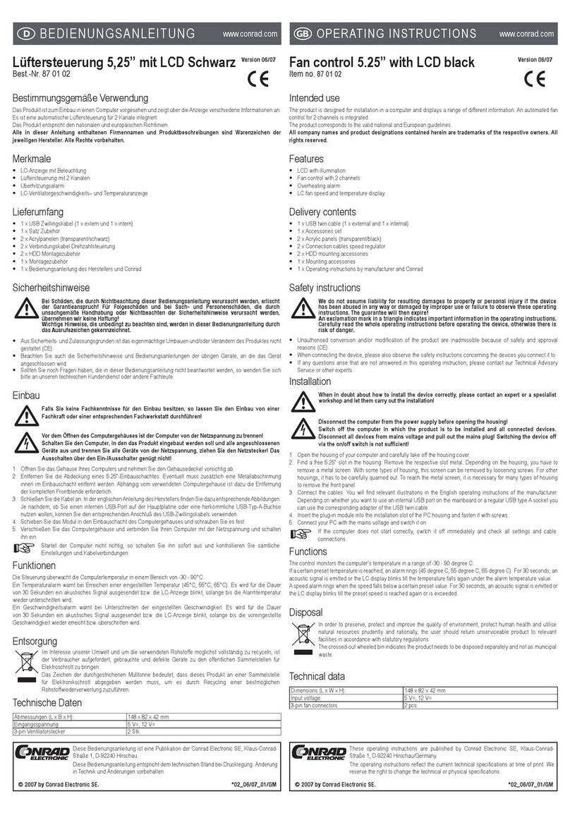
Conrad 87 01 02 User manual

Conrad

Conrad 87 01 02 User manual

Conrad W-Style Premium Jalousie Series User manual

Conrad

Conrad W-Style Premium Jalousie Series User manual

Conrad X10 User manual

Conrad

Conrad X10 User manual

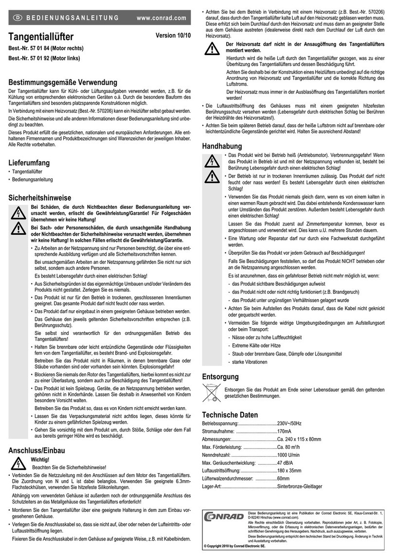
Conrad 57 01 84 User manual

Conrad

Conrad 57 01 84 User manual

Conrad 976974 User manual

Conrad

Conrad 976974 User manual

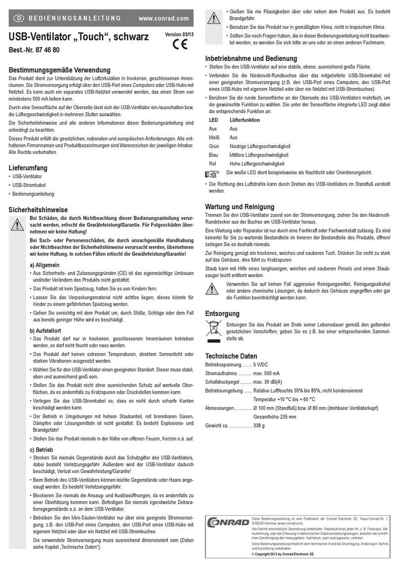
Conrad Touch User manual

Conrad

Conrad Touch User manual

Conrad AKASA AK-FN066 User manual

Conrad

Conrad AKASA AK-FN066 User manual

Conrad 77 69 99 User manual

Conrad

Conrad 77 69 99 User manual

Conrad 88 19 34 User manual

Conrad

Conrad 88 19 34 User manual

Conrad 55 13 98 User manual

Conrad

Conrad 55 13 98 User manual

Popular Fan manuals by other brands

Euromatic KYT40-5 instruction manual

Euromatic

Euromatic KYT40-5 instruction manual

Sulion CAMBIL manual

Sulion

Sulion CAMBIL manual

Bimar VTM33 Instruction booklet

Bimar

Bimar VTM33 Instruction booklet

Lorell 44551 operating instructions

Lorell

Lorell 44551 operating instructions

Swegon ADAPT Sphere c installation manual

Swegon

Swegon ADAPT Sphere c installation manual

THOMSON THVEL491TT instruction manual

THOMSON

THOMSON THVEL491TT instruction manual

Viking VIPR101RSS instructions

Viking

Viking VIPR101RSS instructions

Wohler BC 600 operating manual

Wohler

Wohler BC 600 operating manual

Selkirk Polyflue BH Installation and maintenance instructions

Selkirk

Selkirk Polyflue BH Installation and maintenance instructions

Broan 754RB instructions

Broan

Broan 754RB instructions

Wind River McKenzie WR2009 Series instructions

Wind River

Wind River McKenzie WR2009 Series instructions

Adler AD 7334 user manual

Adler

Adler AD 7334 user manual

tomado TFF4001C instruction manual

tomado

tomado TFF4001C instruction manual

Bestron DWF40REM instruction manual

Bestron

Bestron DWF40REM instruction manual

Vornado iControl Guide de l'utilisateur

Vornado

Vornado iControl Guide de l'utilisateur

emerio FN-109082 instruction manual

emerio

emerio FN-109082 instruction manual

Bionaire BASF40B instruction manual

Bionaire

Bionaire BASF40B instruction manual

Hunter 28420 Installation & operation manual

Hunter

Hunter 28420 Installation & operation manual

manuals.online logo
manuals.online logoBrands
  • About & Mission
  • Contact us
  • Privacy Policy
  • Terms and Conditions

Copyright 2025 Manuals.Online. All Rights Reserved.