7Implementation
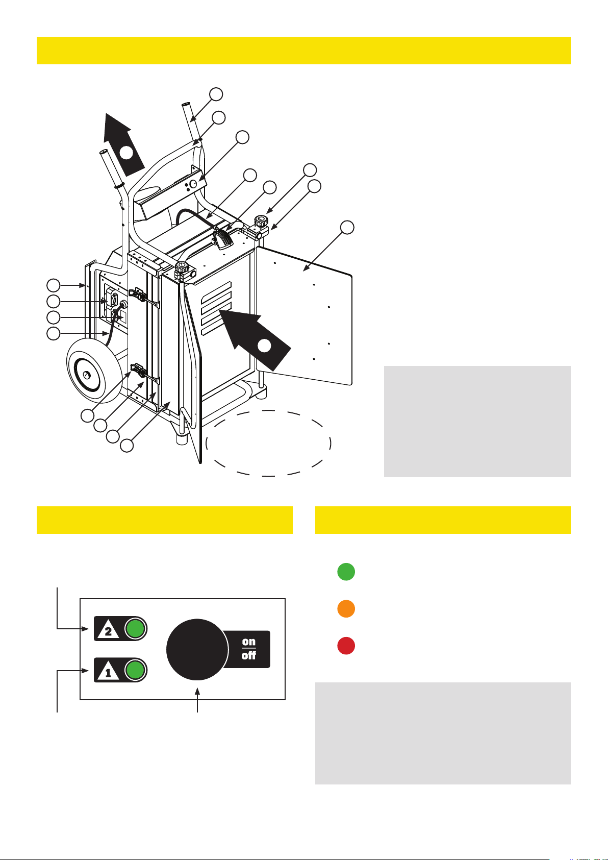
1. Open the air-guiding doors,andplacethemascloseto
theedgesoftheworkingareaaspossible.(Figure 1)
• Thedoorsareunlockedandlockedbylooseningand
tighteningtheknurled-headscrews.
2. Removetheprotectivecapfromtheexhaustairoutlet,if
thereisone.
3. Connect the device to the power gridUseasocketthatis
earthedand,ifpossible,equippedwitharesidualcurrent
device.
• First,thedevicecalibratesthefiltermeasurement
system,andthenitswitchestostandbymode.
• Inthecalibrationmode,bothindicatorlightsflash
greeninturns.
• Inthestandbymode,bothindicatorlightsareflashing
atthesametimeandindicatingthesaturationrateof
thefilters.Seesection8.6.
4. Connect the handheld concrete mixer to the socket of
the device.
• Nomorethan3,000Wmaybeconnectedtothe
sockets.
• Donotconnectextensioncordstothesocketsof
thedevice.Onlyelectricalequipmentusedatthe
workstationmaybeconnectedtothesocketsofthe
device.
5. Start the device.See section 8.2.
• Whenthemachineisrunning,theindicatorlightsare
constantlyonandindicatethesaturationrateofthe
filters.(Figures 2 and 3)
• Ifthedeviceshutsdownandtheindicatorlightsstart
flashingredatthesametime,checkthattheair-guid-
ingdoorsandexhaustairoutletareopenandthatthe
filtersareinplace.Presstheoperatingbuttonagain.
Protectthefloorsurfacebeneaththedevicewith,e.g.,corru-
gatedcardboard,plastichoneycombboard,orplywoodboard,
ifnecessary.
8Use
8.1 Operation at the workstation
Carryoutallthemixing-relatedworkphasesinfrontofthe
device,betweentheair-guidingdoors,andasclosetothesuc-
tioninletaspossible.Alwaysmakesurethatthedeviceisrun-
ningbeforestartingtoworkattheworkstation.
Pleasenotethatdustisproducedwheneverabagofdrymatter
isbeinghandled.Thelargestamountofdustisproducedwhen
thebagis opened,closed,or emptiedand whendrymatter is
mixed.
8.2 Use of the air-guiding doors
Thepurposeoftheair-guidingdoorsistorestrictthesourceof
dusttoassmallanareaaspossible,sothatthedustcanbeef-
fectivelydirectedtothefilters.Dustsuctionisthemosteec-
tivewhentheair-guidingdoorshavebeenplacedclosetothe
rimsofthemixingcontainer.
Theair-guidingdoorsalsofunctionasasplashguard,sothatthe
splatter flying o from the handheld concrete mixer does not
entertheworkingenvironmentandlandonthecompletedsur-
faces.
8.3 Startup and shutdown
Thedeviceisonlyequippedwithoneoperatingbuttonthatis
usedforcontrollingthedevice.
• Oneshort pushstartsthedevicefor5minutes,afterwhich
4 Consair CAMU D2
itswitchestostandbymode.
• Onelong push(5seconds)startsthedevice,anditre-
mainsinoperationuntilitisswitchedobypressingthe
operatingbutton.
Whenthedeviceisrunningandthesuctionison,theindicator
lightsandtheworklightareon.Whenthedeviceisinthestand-
bymode,theindicatorlightsflashsimultaneouslyandthework
lightiso.
8.4 Work light
The device is equipped with an eective 10W LED work light
that is always on when the device is running and the suction
ison.Direct thelighttothemixingcontainer.Thelightmakes
workingattheworkstationfasterandeasier,anditalsomakes
theproduceddustvisible.
8.5 Indication of the need for a filter replacement with
an indicator light (Figures 2 and 3)
Thecontrolpanelofthedeviceisequippedwithtwoindicators
thatindicatewiththeaidofcolouredlightshowsaturatedthe
filters are.The upper light (2) indicates the saturation level of
themainfilterandthelowerlight(1)indicatesthesaturationlev-
elofthepre-filter.
• Whenthegreenindicatorlightison,thefilterisingood
condition.
• Theorangeindicatorlightindicatesanimpendingfilter
change.Whentheorangelightison,thesaturationlevelof
thefilterhasexceeded70%.
• Whentheredindicatorlightison,thefilterisfull.Thede-
vicecannolongermaintainasucientlyhighairflowrate
andthedevice’sabilitytoabsorbdustreduces.
8.6 Indication of fault modes with an indicator light
Thedeviceindicatesfaultmodeswithtwoflashingredindicator
lights.
Ifbothredindicatorlightsareflashingatthesametime,thede-
vicehasdetectedthemodethatpreventsitsuse.
• Checkthattheair-guidingdoorsareopen,theexhaustair
outletisopen,thefiltersareinplace,andthelatchesof
thefilterenclosuresareclosed.
• Thedeviceswitchestoamodethatpreventsitsuseevery
timethelatchesofthefilterenclosuresareopenedand
thefiltersareremovedfromthedevice.Themodethat
preventstheuseofthedevicestopstherotationofthefan
andthusensuressafefilterreplacement.
• Alsocheckthatthemeasurementtubecomingfromthe
intermediatefilterenclosureframeisintactandinits
place.
• Whenyouhaveinspectedthemachine,presstheoperat-
ingbuttonagain.Thedevicecalibratesthefiltermeasure-
mentsystemandswitchestostandbymodeifeverything
isinorder.
Ifbothindicatorlightsareflashingredinturns,thereisafaultin
thedevicethatneedstoberepaired.
• Contactthemanufacturer,retailer,orthecompanythat
leasedthedevice.
8.7 Exhaust air outlet
Thedeviceisequippedwitharound160-mmexhaustairoutlet.
Ifanexhaustpipeisconnectedtotheexhaustairoutlet,itmust
benotedthatthegreaterbackpressureconsequentlydirected
atthefanunitreducestheservicelifeofthefilters.Forthisrea-
son,itisnotadvisabletoconnectanover1-metrelongexhaust
pipetothedevice.Onlyusehardpipewithasmoothsurface.
Iftheexhaustairoutletofthedeviceisconnectedsothatitis
directedoutwardsfromthebuilding,itmustalsobenotedthat
duetofluctuationsintemperatureandairhumidity,condensa-
tion,whichreduces theservicelife ofthe filters,mayoccurin
thefilters.