Console Customs MaxFire FUSION Rapid fire Operation instructions

Installation tutorial for Console Customs Xbox 360
MaxFire – FUSION rapid fire Mod Chip
This tutorial is designed to aid you in installation of a console customs MaxFire LITE modchip This tutorial covers the installation of
our new 14-pin chip This chip only works with “common Ground” style wireless controllers The first part of this tutorial shows
how to find if your controller is a common ground style This chip will not work with matrix style controllers
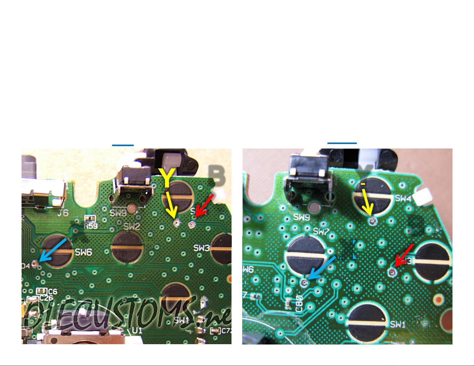
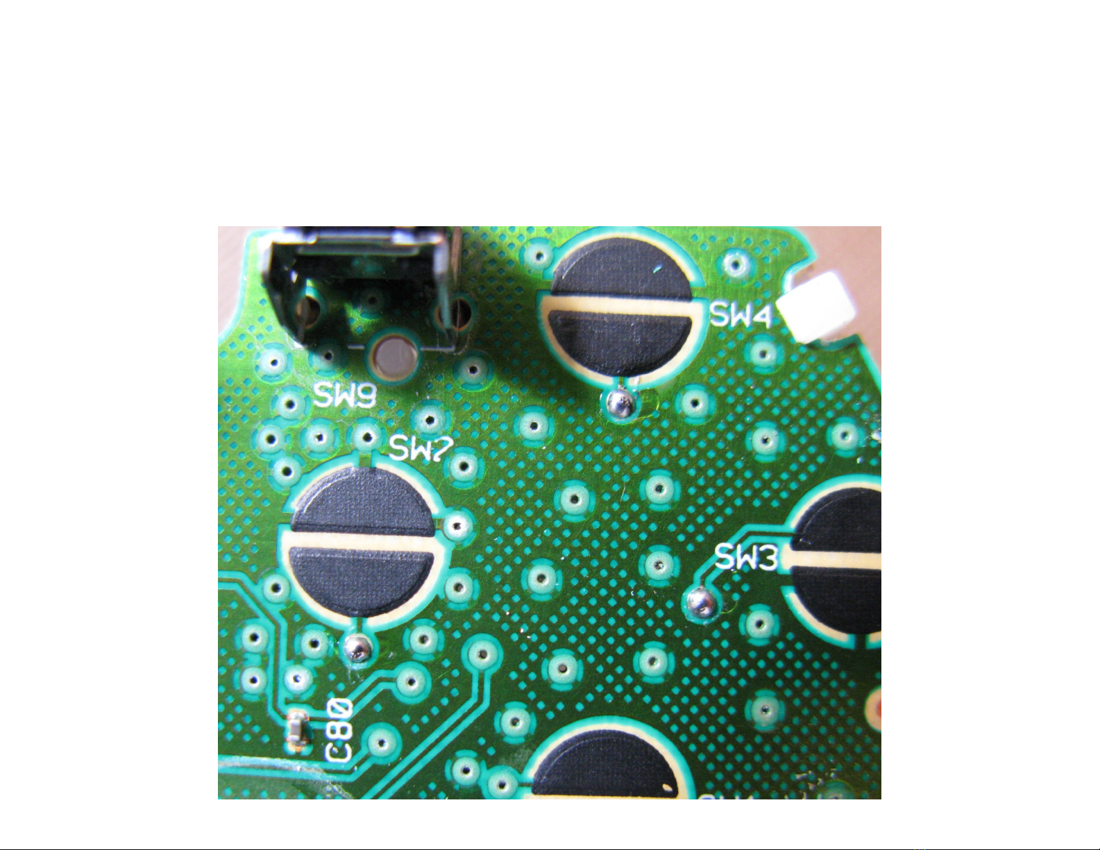
This installation requires soldering several wires to extremely small confined spaces We do not advise attempting this installation if
you are a beginner at soldering We recommend reading through all of the instructions and understand them before beginning
your installation
WARNING: Please proceed with this installation at your own risk. We will not be held responsible for any damage to
yourself your controller your Xbox 360 console or any other equipment.
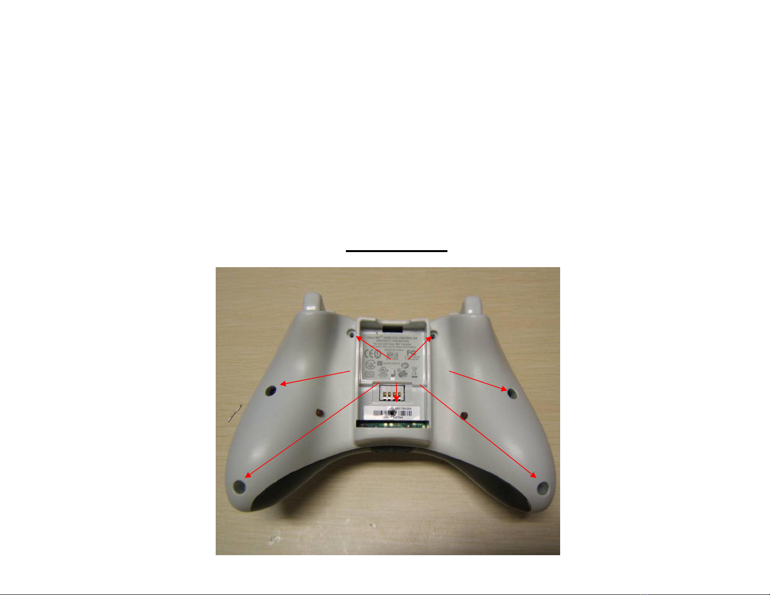
This tutorial requires opening your controller which will void the warranty of your controller.
Tools needed:
• Torx T8 Security/tamper proof driver (For opening wireless controller)
• Soldering iron (A 5w/30w from radio shack is about $12)
• Solder (We use rosin core solder from radio shack so there is no need for flux $4)
• Wire strippers (that can strip 30ga wire, a 30ga wire wrap tool from radio shack includes a 30ga stripper $8)
• Wire cutters
• Hot glue gun
• 9/64th drill bit (or close to it a 1/8th will also work)
• Small pocket knife or razor blade (optional but helpful)
Please visit our website at www.consolecustoms.com

Controller Identification
• Before you get started you need to make sure that you have the correct controller type for this installation Our MaxFire FUSION
Chip requires a CG or CG2 PCB inside your controller This chip CANNOT be installed into a matrix style controller The Left side
images show the board from behind the battery door (no need to open the controller) and the right side is with the controller open
Matrix PCB
From the battery door area you
can see that there is no
Capacitor on the left side while
the other two versions do have a
capacitor
CG PCB
From the battery door area you
can see that the Capacitor is
horizontally oriented
CG2 PCB
From the battery door area you
can see that the capacitor is
vertically oriented

!!STOP!!
This tutorial Covers both CG and CG2 style
controllers The Solder locations for the X, Y and
B buttons are in different locations on these two
board types Please be sure you have properly
identified you controller from the previous page
before continuing so you are sure to use the
correct solder points
!!STOP!!

Step 1: First lets start by looking at what is in your kit
• You should have the following items in your kit
1 (1) 14 pin PIC microcontroller
2 (2) Buttons
3 30ga Wire ( We include multiple colors)

Step 2: You will start by taking the PIC chip and putting it on its back, also called
(dead bug) Note the location of the notch that is on the top of the chip, the pin
numbers and their purpose
Notch
1
2
3
4
5
6
78
Power
Fast Reload Button
Not Used
B Button
right trigger
Ground
Y Button
9
10
11
12
13
14
RB Button
Left trigger
Not Used
Player 3 LED
Player 4 LED
X Button
Mod Button

Step 3a: You will now attach the wires to the chip using solder
We use several color wires here to help show where each wire goes Your kit will contain 5 colors of wire
Notch
7 6 5 4 3 2 1
Starting with pins 1-7:
•Pin 1: This is the power wire and is red in the image, this
wire should be aprox 2 5 inches long
•Pin 2: This is the white wire and is for the Mod button you will
install , this wire should be 2 5” long
•Pin 3: This is the Yellow wire and is for the Fast Reload
button you will install , this wire should be 5” long
•Pin 5: This is the Green wire and will go to the RB button,
this wire should be 3 5” long
•Pin 7: This is the Blue wire will go to the Left trigger, this wire
should be 5” long
•tip: Only strip about 1/8” of the wire for soldering. Exposing
more bare wire could cause a short.
•tip: For information on proper soldering isit
http://www.curiousin entor.com/guides/How_To_Solder

Notch
14 13 12 11 10 9 8
Step 3b: Continuing to the other side of the chip
pins 8-14:
•Pin 8: This is the long white wire for the Player 3 LED and
should be 2 25 inches long
•Pin 9: This is the medium length white wire for the Player 4
LED and should be 2 inches long
•Pin 10: This is the long blue wire for X button and should be
1 5 inches long
•Pin 11: This is the Yellow wire for Y button and should be 2
inches long
•Pin 12: This is the Red wire for B button and should be 2
inches long
•Pin 13: This is the short blue wire for right trigger and should
be ¾ of an inch long
•Pin 14: This is the short white wire which will go to ground
and should be ¾ of an inch long
•tip: Only strip about 1/8” of the wire for soldering. Exposing
more bare wire could cause a short.
•tip: For information on proper soldering isit
http://www.curiousin entor.com/guides/How_To_Solder

Step 4: Opening the controller
•Remove the 7 screws indicated below One is behind the small white label
• The wireless controller requires a T8 Torx security driver This is a star shaped tip with a hole in the middle
of it It is very difficult to open the wireless controller without this
SCREWS
WIRELESS

Step 5: Prep the X Y and B solder pads (also called Vias)
• To connect the wires from the chip to the X, Y and B buttons you will need to first need to remove the green
coting that is coving the pads This is easiest done with a small pocket knife or razor blade Lightly scrape
the green coating to expose the bare copper underneath Be carefully to only scrape the coating from the
pad, the area surrounding the pad is a ground plane and exposing metal on the ground plane opens up the
possibilities for a short
• The pads on CG and CG 2 are in different locations Check the images below for your controller and the pad
locations In these images the pads have already been scraped clean
CG CG2
X
YB
X
Y
B

Step 6: Tin the X Y and B solder pads
• Next you will want to Tin the pads Tinning mean you want to coat the pad with solder This makes connecting
the wire later much easier To do this you will want to place the tip of your soldering iron on the pad to heat the
pad and touch the solder to the pad (try avoiding touching the solder to the soldering iron) and the solder
should flow onto the pad You should end of with three little bubbles of solder like you see below Anymore that
what you see here is to much and should be removed

Step 7: Mounting the chip to the PCB using hot glue.
•Mount the chip on it’s back (dead bug) with hot glue so it is exactly in-between the thumbstick
and the large hole to the right The chip will sit on top of the pins from the rumble motor, so you
will need to be sure to use enough hot glue to hold it in place
• Note the orientation from the location of the notch that is on the top of the chip
Notch

Step 8: Solder the left trigger wire.
•In this step you will need to take the wire from pin 7 and first run it along the bottom of the PCB as
shown in the left image Use some hot glue to hold the wire in place so that it does not catch on
anything when putting the controller back together
• Next trim the wire so that you do not have extra wire and strip only 1/8” of the end of the wire
Then use your soldering iron to attach the wire to the middle of the three trigger pins as show in the
right side image
Tip: trim you wires so they are only as long as you need, then strip the end and solder into place. Long wires will
just cause a place for something to snag when closing the controller.
Hot glue Here Solder to
middle of the
3 trigger pins

Step 9: Attaching the right trigger wire and ground wire.
• In this step you will first attach the white ground wire form Pin 14 and the blue Right trigger wire
from pin 13 These should be soldered to the right trigger as shown in the image below
tip: keep your wires as short as possible so they do not interfere with the buttons when putting the controller back
together
Notch
Ground Right
Trigger

Step 10: Attaching the X Y and B button wires.
• Now you will need to attach the X (pin 10), Y (pin 11) and B (pin 12) button wires It is important
to keep the wires as short as possible and keep the out of the black circles If you cross over a
black circle it could possibly prevent one of the buttons on your controller from working when you
put it back together Also be sure to use only a small amount of solder as we have done
• The picture below is of a CG2 board

Step 11: Attaching the LED wires.
• Now you will install the wires to control the Player 3 and 4 LEDs Be sure to cut the wires to the exact length
needed and again keep the wires out of the black circles on the board
• Solder the wire from Pin 9 to the bottom of the player 4 LED You must be careful with this as the LED’s are very
fragile and leaving your soldering iron on the end to long could damage the LED Only touch the very end of the
LED with your soldering iron DO NOT touch the longer sides or the center of the LED because you will destroy it
• Next Solder the wire from Pin 8 to the bottom of the Player 3 LED
• The Left image shows the path your wires should follow and the right is a close-up of the LED’s

Step 12: Attaching the power wire.
• Solder the wire from pin 1 to the power for the headset as shown The bottom picture
shows a close-up of the solder point
Solder Here
Plastic clip from headset
Solder Here

Step 13: Attaching the RB Button wire.
• Solder the wire from pin 5 (green wire) to the top of the RB Button as shown You must be careful
and make sure that the wire or solder does not make contact to the metal back support for the RB
button
• Again make sure the wire is kept short and out of the path of the black circles
• Finally use a small amount of hot glue to hold the wires in place It is best to hot glue the wires
and not over top of the solder joints in-case something needs to be fixed later

Step 14: Onto the case and buttons. Here we will drill the holes needed for the
buttons and secure them in place.
• Drill holes using your drill bit in the spots indicated or where ever you would like to have your buttons We
prefer keeping them out of the way because you will only need to press them to change modes
• Next take your buttons and we are going to remove one pair of legs
from each
because we only need one pair Use the image to the right so you know which
legs to remove
• Next use hot glue to secure the buttons
in place Do not attempt to use super glue
or other adhesives as it will soak into the button mechanism and cause it to stop
working Once the buttons are
secured in place bend the two legs out flat away from
the button
REMOVE
Drill holes here

Step 15: We will now connect the wires to the buttons
• First you will want to solder a wire from one leg of the right side button to one leg of the left side button leaving
about 1 5” extra wire after the left side button To do this take one piece of wire and use your soldering iron to
melt off part of the casing from the button so you can use one continuous wire You will attach the end of the
wire to ground inside the controller later
• Next take the controller circuit board and flip it over and bring it in close to the back half of the case Take the
white wire that you have left (From pin 2) and solder it to the remaining pin of the right side button
• Then take the Yellow wire that you have left (From pin 3) and solder it to the remaining pin of the left side
button
• Use some hot glue to hold everything in place then flip the circuit board over onto the back half of the shell
To ground

Step 16: The final connection! Connect the buttons to ground.
• For the last connection solder the wire that is connecting the two buttons together to ground inside the
controller The easiest place to solder this is using the bottom pin of the left trigger as shown below
Ground
Table of contents
Other Console Customs Video Gaming Accessories manuals