Consort CST-M10/54BH415 User manual

GCL System Integration Technology Co., Ltd

CONSORT SOLAR CO., LTD.
ETERNAL SUN VALUE CREATOR
01
01
CONTENTS
Purpose of this Manual............................................................................................................... 2
Disclaimer................................................................................................................................... 2
Safety & Transport......................................................................................................................3
Mechanical Installation...............................................................................................................7
Electrical Installation................................................................................................................ 14
Grounding................................................................................................................................. 16
Bypass Diodes and Block Diodes............................................................................................. 17
Maintenance..............................................................................................................................18

PURPOSE OF THIS MANUAL
02
CONSORT SOLAR CO., LTD.
ETERNAL SUN VALUE CREATOR
This manual applies exclusively to the solar photovoltaic module (here in after referred to
as Module) of Wuxi Consort Science Technology Co., Ltd. (here in after referred to as
CST). The contents of this manual involve the installation methods, operation safety and
maintenance information of CST’s Modules.
Modules must be installed by professionals. Please read this manual carefully before
installation. The installers must follow all the rules in this manual strictly as well as local
requirements and regulations by law or authorized organizations.
Before installing, the installer must be familiar with their mechanical and electrical
requirements. Please keep this manual in a safe place for future reference (care and
maintenance) and in case of sale or disposal of the Modules.
DISCLAIMER
CST shall not be responsible for any loss arising from the installation, operation, use or
maintenance of the Modules which is not complying with the guidance of this manual,
including breakdown or damage of the Modules or any other expenses incurred.
Any customer shall not get any patent or authorization of the patent when using the
Modules, expressed or implied. Any infringement of patents or other rights of the third
party, which may result from the use of the Module, is not within the responsibility scope
of CST. The information in this manual is based on CST’s knowledge and experience and
is believed to be reliable, but such information including product specification (without
limitation) and relevant suggestions do not constitute a warranty, expressed or implied.
CST reserves the rights to change the manual, the Modules, the specifications or any
other information of the Modules without prior notice.

SAFETY & TRANSPORT
CONSORT SOLAR CO., LTD.
ETERNAL SUN VALUE CREATOR
04
General Detailed Rules
Keep all the Modules and electrical connectors clean and dry before installation.
Use both hands to carry Modules. Do not overlap Modules.
Be cautious when carrying Modules. Slip-proof gloves are necessary.
Use supportive disassembling tools when unpacking.
The application level of CST module is Class A, which can be used in systems operatingat
greater than 50 V DC or 240W, where general contact access is anticipated.
Do not stamp on Modules or put weight on Modules.
Do not disassemble or drop Modules. Do not remove any nameplate or component
of the module.
Do not use mirrors or magnifiers to concentrate sunlight onto Modules.
Do not lift the module by grasping the junction box or cable wire.
Do not use any sharp object with Modules.
Do not directly apply pressure on the glass surface or backsheet of Modules.
Do not touch the surface of the coated glass with bare hands.
Ensure all contacts and the operating environment are clean and dry.
Module Carry and Installation Instruction
Both hands when handling Modules
Ensure Modules are fixed properly
Do not use sharp objects with Modules
Do
not pull the wiring cables or junction
box
Do not stamp on Modules
Do not touch Modules with bare or dirty
hands
Do not pile up Modules on uneven ground
Do not drop or throw Modules
03

SAFETY & TRANSPORT
CONSORT SOLAR CO., LTD.
ETERNAL SUN VALUE CREATOR
04
Description of Package Signs
Before the operation, it is necessary to read carefully the unpacking instruction and outer
packing box instruction, and carry out the operation as instructed.
1. DO NOT expose the module to rain or
moisture.
2. The Modules in the carton box are fragile.
Handle with care.
3. The package shall never be upside down
during the transportation.
4. It is prohibited to tramp on the packing
box and module.
5. During the stacking of the Modules, the
outer packing box can be stacked not
exceed the maximum layer allowed .(n=2
means it is allowed to stack for at most
two layers.)
n
6. One module shall be handled by two
people together.

SAFETY & TRANSPORT
CONSORT SOLAR CO., LTD.
ETERNAL SUN VALUE CREATOR
05
Unloading, Transportation and Storage
When the Modules are delivered to the project site, the freight car shall be ready in the
flat, even and open area for parking and unloading.
Forklift unloading: Choose the appropriate carrying forklift according to the commodity
weight, unload the Modules from the freight car and place them on flat ground.
Unloading with a crane: Affix the lifting belt in the wood supporting frame buckle (Fig. 1,
2). It is allowed only to lift one pallet at a time. Before lifting, it is necessary to confirm
whether the pallet and paper box are damaged and ensure that the lifting rope is robust
and firm. When being lifted close to the ground, the paper box will be gently placed in a
relatively flat position on the project site by two people, one on each side.
Figure 1 Wood Supporting Frame Figure 2 Lifting Schematics
It is prohibited to stack the Modules in the project site.
During the transportation at the project site, the Modules shall not be stacked, but only
allowing for one layer in transportation.

SAFETY & TRANSPORT
CONSORT SOLAR CO., LTD.
ETERNAL SUN VALUE CREATOR
06
Storage in the project site warehouse:
Storage environment requirements: Humidity<85%, temperature -20 ~+50℃; Modules
statically stacked for ≤2 layers.
Temporary storage at the project site: The Modules shall be stored in a dry, well-
ventilated place. They shall not be stacked but shall be covered with waterproof cloth to
prevent dampness in the Modules.
Unpacking description
1. In the outdoor unpacking process, it is prohibited to operate in rainy conditions;
2. If there is wind in the field, special attention shall be paid. Particularly in the event of
heavy wind, it is recommended not to handle the module, and it is necessary to properly
secure the unpacked Modules;
3. The working surface shall be such that the packing box can be placed in a stable, level
position, avoiding being overturned;
4. During the unpacking, it is necessary to wear protective gloves, and avoid scratching
the hands and leaving the fingerprints on the glass;
5. In the case of operation not according to the requirements or in the case of an
unskillful operation, it will result in the fall-off of the protective corner in small amounts,
which will be normal. The effect of the protective corner is to reduce damage due to external
force during transport, and the fall-off of the protective corner will not influence the reliability
of the Modules;
6. Before the unpacking, it is necessary to carefully check the product information on the
carton box, and carefully read the unpacking instruction;
7. Every module shall be carried by two people. When carrying the module by two
people, it is prohibited to pull the junction box.

MECHANICAL INSTALLATION
CONSORT SOLAR CO., LTD.
ETERNAL SUN VALUE CREATOR
07
Location Selection
Select suitable places to install Modules. The module in the north latitude region shall
face south, and shall face north in the south latitude region.
Install Modules at the places with sufficient sunlight and without shade at any time. If a
module is shaded or even partially shaded, it will result in lower power output. A
permanent or regular shade will cause module damage, which will result in the invalidity
of product’s limited warranty.
Do not store, install or use Modules at the places where combustible gas is easily
generated or gathering.
The straight-line distance between the installation site and coastline shall not be shorter
than 1 km unless there is a writ ten approval from CST or an engagement specified in the
contract.
Location Selection
Modules in the same string should be installed at the same angle. Modules installed in
different angles will receive different irradiation, which will cause current different. As a
result, it will decrease the operation efficiency of the system.
Please refer to Table 1 for the recommended mounting tilt angles of the Modules.
Local latitude
Mounting Tilt Angles
0°-15°
15°
15°-25°
Local latitude
25°-30°
Local latitude + 5°
30°-35°
Local latitude + 10°
35°- 40°
Local latitude + 15°
>40°
Local latitude + 20°
Table 1 Mounting Tilt Angle of Modules

MECHANICAL INSTALLATION
CONSORT SOLAR CO., LTD.
ETERNAL SUN VALUE CREATOR
08
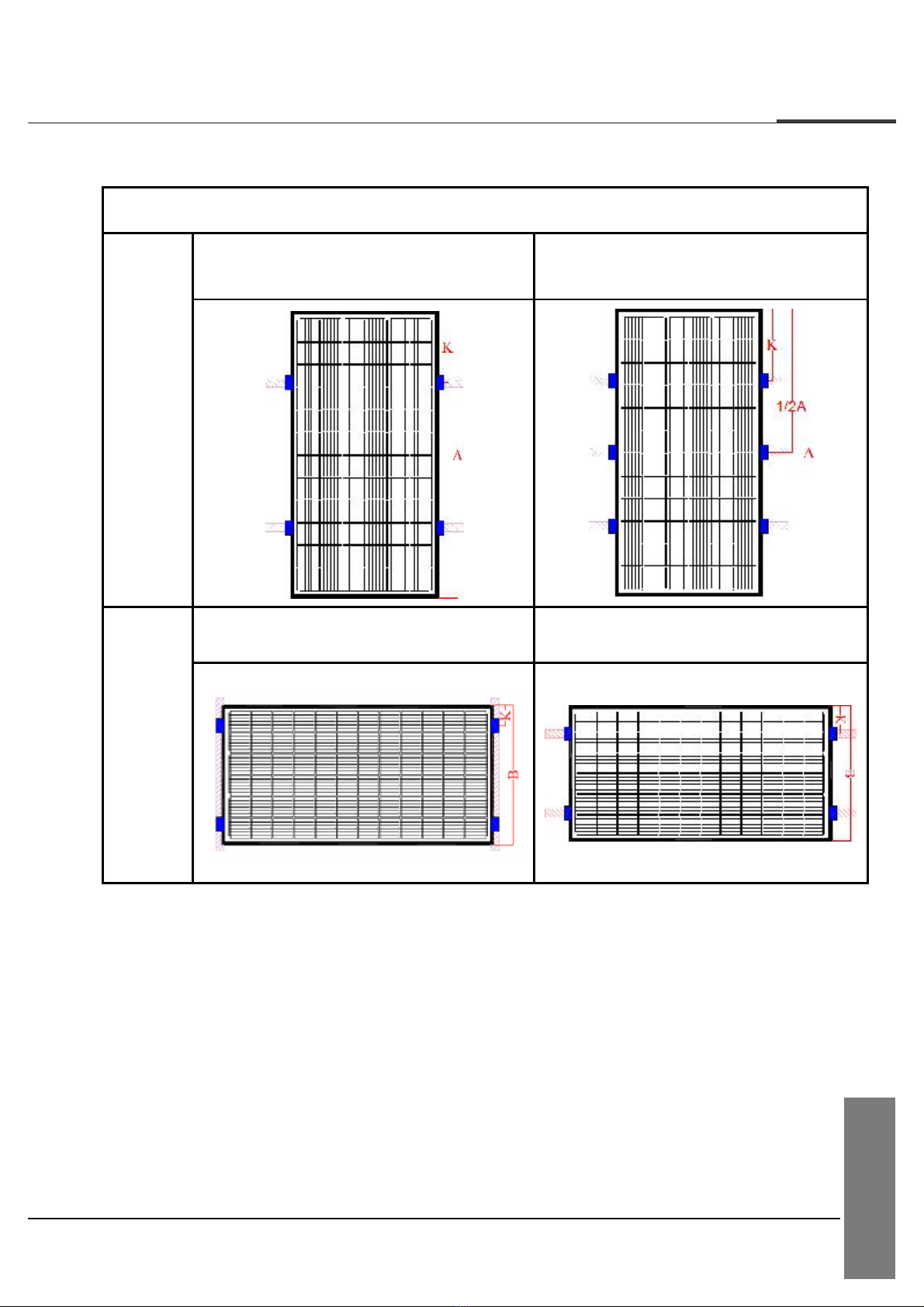
Installation requirements
Ensure the module installation method and support system sufficiently robust, so that
the Modules can undertake the preset loading conditions, the support installer or
supplier shall provide necessary guarantee and other related certifications. The
installation support system shall pass the inspection and test by the third-party test
institution with the static mechanic analysis capability, and use the local national or
international standards, such as DIN1055 or equivalent.
The support structure shall be made of the durable, corrosion resistant and ultraviolet
resistant materials.
The module shall be firmly mounted on the support.
Choose proper installation height of the photovoltaic support system, and ensure the
lowest part of the module is high enough, to avoid being shaded by plant or being
damaged by the flying sand. Or being covered by snow for a long time in winter.
When the module is installed on the roof or the building, it is necessary to ensure that
the roof structure is fixed firmly and will not be damaged by heavy wind or heavy
snow, and the back of the module shall be well-ventilated to facilitate the cooling of
the module (the minimum gap between the module and installation surface is 10cm).
Considering the influence of linear thermal expansion of the module frame, the
minimum distance between two Modules should not be less than 10mm.
Ensure that the module backside will not contact the support or architectural structure
even if there is the module surface is under the external pressure.
It is required to observe the instruction guide and safety rules attached on the support.
It is not allowed to drill the hole in the glass surface or frame of the module.
otherwise ,the guarantee will be invalidated
When to install the Modules on the roof, it is necessary to guarantee the roof
structure is suitable for the module installation. And the installed modules should not
be beyond the roof zone. Additionally, the roof area where it is penetrated by module
installation shall be properly sealed to prevent the roof from water leakage.
When the module is installed on the supporting column, it is necessary to ensure the
supporting column and module installation structure is capable of withstanding the
expected local wind.

MECHANICAL INSTALLATION
CONSORT SOLAR CO., LTD.
ETERNAL SUN VALUE CREATOR
09
1、Framed Modules
Installation with the mounting clamp
Table 2 Installation Method
Clamping
on the
long side
Installation Method B
Installation Method C
Clamping
on the
short side
Installation Method D
Installation Method E
Note: The length of the clamp≥50mm.

MECHANICAL INSTALLATION
Table 3 Installation method and load capacity
CONSORT SOLAR CO., LTD.
ETERNAL SUN VALUE CREATOR
10
Installation Method
Installation Method B
Installation Method C
Installation Method D
Installation Method E
Module Type
Module
dimensions
(mm)
Position
of
clamp K
(mm)
Design
load :
downward
/ upward,
γm=1.5
(Pa)
Position
of
clamp
K
(mm)
Design
load :
downward
/ upward,
γm=1.5
(Pa)
Position
of
clamp
K
(mm)
Design
load :
downward/
upward,
γm=1.5
(Pa)
Position
of
clamp
K
(mm)
Design
load :
downward/
upward,
γm=1.5
(Pa)
CST-M8/72HXXX
CST-M8/72BHXXX
2094*1038*35
473-573
3600/1600
——
——
25~260
1600/1600
25~260
1600/1600
CST-M8/60HXXX
CST-M8/60BHXXX
1755*1038*35
392-492
3600/1600
——
——
25~262
1600/1600
25~262
1600/1600
CST-M10/78HXXX
CST-M10/78BHXXX
2443*1134*35
554-654
3600/1600
233-233
1600/1600
233-333
1600/1600
2465*1134*35
560-660
233-233
233-333
CST-M10/72HXXX
CST-M10/72BHXXX
2256*1133*35
514~614
3600
1600
——
——
233-333
1600/1600
233-333
1600/1600
2279*1134*35
520~620
——
——
233-333
233-333
CST-M10/66HXXX
CST-M10/66BHXXX
2073*1133*35
468-568
3600
1600
233-333
1600/1600
233-333
1600/1600
2094*1134*35
473-573
233-333
233-333
CST-M10/60HXXX
CST-M10/60BHXXX
1890*1133*35
422-522
3600
1600
——
——
233-333
1600/1600
233-333
1600/1600
1908*1134*35
427~572
——
——
233-333
233-333
CST-M10/54HXXX
CST-M10/54BHXXX
1722*1134*35
380~480
3600
1600
——
——
233-333
1600/1600
233-333
1600/1600
CST-M12/60HXXX
CST-M12/60BHXXX
2172*1303*35
493~593
3600
1600
——
——
275-375
1600/1600
275-375
1600/1600
CST-M12/66HXXX
CST-M12/66BHXXX
2384*1303*35
546~646
3600
1600
——
——
275-375
1600/1600
275-375
1600/1600
Note: Test load = γm(safety factors) × design load

MECHANICAL INSTALLATION
CONSORT SOLAR CO., LTD.
ETERNAL SUN VALUE CREATOR
11
Installation Method F
Mounting
on the
long side
Table 4 Installation Method
Installation with the mounting hole

MECHANICAL INSTALLATION
CONSORT SOLAR CO., LTD.
ETERNAL SUN VALUE CREATOR
12
Table 5 Mounting dimension and load capacity
Module Type
Module dimensions
(mm)
Mounting
distance M
(mm)
Mounting
distance N
(mm)
Installation
Method F
Design load :
downward/
upward, γm=1.5
(Pa)
CST-M8/72HXXX
2094*1038*35
990
989
1600/1600
1300
989
3600/1600
CST-M8/60HXXX
1755*1038*35
990
989
1600/1600
1300
989
3600/1600
CST-M10/78HXXX
2443*1134*35
400
1084
1600/ 1600
990
1084
3600/1600
1400
1084
3600/1600
2465*1134*35
400
1084
1600/ 1600
990
1084
3600/1600
1400
1084
3600/1600
CST-M10/72HXXX
2256*1133*35
400
1084
1600/ 1600
990
1084
3600/1600
1400
1084
3600/1600
2279*1134*35
400
1085
1600/1600
990
1085
3600/1600
1400
1085
3600/1600
CST-M10/66HXXX
2073*1133*35
400
1084
1600/1600
990
1084
3600/1600
1400
1084
3600/1600
2094*1134*35
400
1085
1600/1600
990
1085
3600/1600
1400
1085
3600/1600
CST-M10/60HXXX
1890*1133*35
400
1084
1600/1600
990
1084
3600/1600
1400
1084
3600/1600
1908*1134*35
400
1085
1600/1600
990
1085
3600/1600
1400
1085
3600/1600
CST-M10/54HXXX
1722*1134*35
1150
1085
3600/1600
1400
1085
3600/1600
CST-M12/60HXXX
2172*1303*35
400
1254
1600/1600
1400
1254
3600/1600
CST-M12/66HXXX
2384*1303*35
400
1254
1600/ 1600
1400
1254
3600/1600
Note: Test load = γm(safety factors) × design load

MECHANICAL INSTALLATION
CONSORT SOLAR CO., LTD.
ETERNAL SUN VALUE CREATOR
13
The Modules may be installed and fixed with the following methods:
Mounting hole system: Use the corrosion-resistant M8 bolt, for fixing with the
installation support through the installation hole in the side frame of the module, as
shown in Fig. 5.
Clamping system: use proper clamp, and fix the module with the installation support, as
shown in Fig. 6.
Figure 5 Mounting holes
Figure 6 Mounting clamps
The mounting accessories recommended are listed below:
Bolt
Flat washer
Spring washer
Nut
Material: stainless
Steel material: stainless steel
Material: stainless steel
Size: M8
Size: M8
Size: M8
Size: M8
The range of torque for screw tightening is 14N.m to 20N.m.

ELECTRICAL INSTALLATION
CONSORT SOLAR CO., LTD.
ETERNAL SUN VALUE CREATOR
14
DC power generated by the photovoltaic system can be converted into AC power and fed
into the grid. Policies on connecting renewable energy system to the grid vary from region to
region. Consult senior system designer before designing the system. Generally, the system
installation shall be formally approved by the local public sector.
General Installation
Installation structure should be compatible with module, in order to avoid galvanic
corrosion. Any defects caused by such corrosion will void the warranty.
The DC-side system potential of the photovoltaic array includes the practice of floating
ground, positive-pole grounding and negative-pole grounding according to the system
requirements; and different cell technologies have different adaptability. In a power-
station project, particularly the module of the crystalline silicon photovoltaic cells, too
large an absolute value of the negative to the ground might cause potential induced
degradation (PID). Consequently, it is appropriate to use the negative grounding system
so that the potential of the circuit is positive. Consult the inverter manufacturer for details.
It is forbidden for non-professionals to open the lock nuts of the connector. Make sure
that the connectors are clean, dry and fully connected.
(A click sound should be heard when fully connected), otherwise it may lead to electric
arc sparks which will damage the connector or cause a fire.
Under normal conditions, a module is likely to experience conditions that produce more
current and/or voltage than reported at standard test conditions, Accordingly, the values
of ISC and VOC marked on the Module should be multiplied by a factor of 1.25 when to
determining component voltage ratings, current ratings, fuse sizes, and size of controls
connected to the PV output.
Completely cover the Modules with an opaque material to prevent electricity from being
generated during disassembling the conductors.
It is not allowed to use the Modules in different models in the same solar photovoltaic
system. When the Modules are connected in series, the voltage of every string shall not
be higher than the maximum voltage of the system (as shown in Figure 8). Reference
equation of the maximum number of the Modules in serial connection: maximum system
voltage of the module/ (1.25* open-circuit voltage).
When connected in parallel, the current output is equal to the sum of each string’s current
(as shown in Figure 9). Fuse is necessary for each module string. Take reference to the
local regulation. Recommended maximum parallel Modules configurations: Fuse rating/
(1.25* short-circuit current).

ELECTRICAL INSTALLATION
CONSORT SOLAR CO., LTD.
ETERNAL SUN VALUE CREATOR
15
Figure 8 Connection in Series Figure 9 Connection in parallel
Refer to the local regulations to determine the system wire size, types and temperatures.
The cross section of the cables and the capacity of the connectors must be selected to suit
the maximum system short circuit current (The recommended section area for a single
piece of Module is 4 mm2, and the recommended rated current for the connector is greater
than 10A), otherwise the cables and connectors shall be overheated under large current.
Caution: The maximal temperature of the cable is 85 ℃while the upper limited
temperature of the connector is 105℃.
Make sure the electric components such as the connectors and inverters are off-state
during the installation. To reduce lightning damage, the loop area should be kept as small
as possible when laying cables. It is recommended to use fuses in each string.

GROUNDING
CONSORT SOLAR CO., LTD.
ETERNAL SUN VALUE CREATOR
16
Grounding by cable
The grounding bolts must be made of stainless steel and be used in the specified
grounding holes. First, make the M3. 5 stainless steel bolt pass through the spring
washer, flat washer, cup washer (copper conductor with a diameter of 2.1 mm) and
star washer, and then insert through the grounding hole, flat washer and spring
washer on the frame. Finally, tighten with a M3.5 nut. Caution: The upper limited
temperature of the conductor is 85℃. As for the installation, refer to Figure 10.
Grounding by lugs
All the module frames and mounting structures shall be grounded according to
regional and national electricity regulations. Use recommended hardware to connect
grounding cables and fasten to the Module frames.
While using the metal structure, make sure the surface of the system have been
electroplated to keep a good conducting circuit.
Use suitable grounding conductors to connect the Module frame to the mounting
structure. This can achieve proper grounding effects.
The grounding conductor must be connected to ground via an appropriate grounding
electrode. It is recommended to use lugs to connect the grounding cables. I f it is
only mechanically connected to a grounded module without bolts and nuts, the
mounting system should be grounded as well.
First, peel the grounding cable to a proper length without damage to the metal core.
Then insert the peeled cable into the lug, tighten the screw. As shown in Figure 11,
connect the lug to the aluminum frame with stainless steel bolts and connection
components. The recommended tightening torque for M3 bolts is 2.3N•m.
Nut(M3.5,SS) Nut(M3,SS)
Spring washer(SS)
Flat washer(SS)
Star washer(SS)
Frame
Copper wire
Flat washer(SS)
Cup washer(SS)
Spring washer(SS)
Bolt (M3.5, SS)
Spring washer
Flat washer
Star washer
Frame
Bolt (M3, SS)
Grounding Lug
Grounding
cable
Figure 10 Figure 11

BYPASS DIODES AND BLOCK DIODES
CONSORT SOLAR CO., LTD.
ETERNAL SUN VALUE CREATOR
17
In a system with two or more Modules connected in series, if part of a Module is shaded
while the other part is exposed to the sun, a very high reverse current will go through the cells
which have been partly or entirely covered and it will cause overheat on the cells, which may
damage the Module. Using bypass diodes can protect Modules from this kind of risk. There
are bypass diodes in junction boxes, which can reduce the effects of partial shadows. Do not
privately disassemble the junction box to replace the diodes, even when the diodes are broken.
This should be processed by the professionals.
In a system with batteries, if the controller doesn’t have the function of backswing
protection, block diodes installed between the battery and the Module can prevent the reverse
current from damaging the Module.

MAINTENANCE
CONSORT SOLAR CO., LTD.
ETERNAL SUN VALUE CREATOR
18
Normally, the Modules do not need repair. Follow the maintenance methods below to
ensure the best performance of the Modules:
In most conditions, the normal rainwater can keep the module glass clean. Clean the glass
surfaces with wet soft sponge or cloth if necessary. Use mild non-abrasive cleaning agent
to remove stubborn dirt.
Do not try to clean a Module with broken glass or perforated backsheet. It will cause
serious electrical shock. Take a regular inspection on grounding, mechanical and
electrical connections every 6 months. Make sure all the Module connectors are
connected, clean and without damage or corrosion.
When disassembling the connectors, must make sure all the components are working well;
otherwise the connector’s shall be replaced. Damage on the connector will cause
electronic leakage. The tightening torque of the nut should be 1.5 N • m - 3 N •m.
Use opaque material to completely cover the Modules during repair to avoid electric
shock. When exposed to the sunshine, the Modules will produce high voltage. The repair
work must be carried out by professionals.
Warning: Shut down the system before any electric repair.
Improper maintenance may cause electric shock or fire.

CONSORT SOLAR CO., LTD.
Add :No.20, Jinqi Road, Yuqi Supporting Area, Huishan Econmic Development Zone,
Wuxi, Jiangsu, P.R.China
Tel:+86 510 6822 3668
Fax:+86 510 6822 3668
Mob:+86 139 6171 3023
www.consortsolar.com
Table of contents
Popular Solar Panel manuals by other brands

ACOPOWER
ACOPOWER HY-PTK-100WP20A user manual

Bosch
Bosch c-Si M 60-225-16 Installation and safety manual

Qcells
Qcells Q.PEAK DUO L-G6.3 / BFG Installation and operation manual

CanadianSolar
CanadianSolar CS5AH-180M INSTALLATION MANUAL OF REPLACEMENT

Go Power
Go Power GP-PSK-90 user manual

GOAL ZERO
GOAL ZERO Boulder 200BC user guide