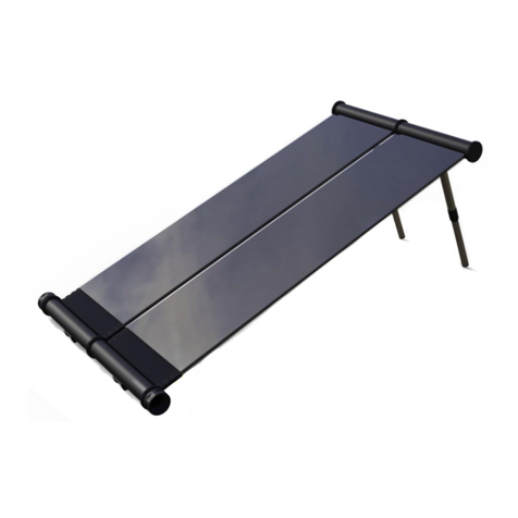
SLK SOLAR PV MODULE User manual

AssemblyinstructionsforSLKSolarroofmountsystem‐RevL Page1of38
ASSEMBLYINSTRUCTIONSFORSLKSOLARPVMODULE
ROOFMOUNTSYSTEM
TABLEOFCONTENTS
NoticesandsafetyPage2
GeneralprocedurenotesPage4
InstallationmaterialsandtoolsPage5
PartdiagramsPage5
ElevationViewsPage7
AssemblysequencePage9
TiltbracketassemblyandinstallationPage10
SubstrateassemblyPage12
Panelassembly:
4x1&3x1Page13
GeneralmoduletospargroundingPage17
TiltAccessFeaturePage18
PanelinstallationPage19
LaterallinkassemblyPage21
WinddeflectorassemblyPage22
BallastpaninstallationPage28
ConnectorinstallationPage32
SparfielddrillingPage34

AssemblyinstructionsforSLKSolarroofmountsystem‐RevL Page2of38
NOTICESANDSAFETYPRECAUTIONS
Readthisdocumentbeforebeginninginstallationwork.Planforsafepracticeduringanyinstallationactivitywithrespectto
hazardsfromtripping,falling,lifting,repetitivestress,andanyoverheadorelectricalhazards.Whenworkingclosetobuildingroof
edges,considerprotectionoptionsthatreduceworkerexposuretofallhazards.RefertoOSHASub‐Chapter7,Group1,Article2.
TheSLKSolar®RoofMountSystem(RMS)ismadefromaluminumalloy,fastenedtogetherwithstainlesssteelassemblyhardware.
AluminumalloycomponentsaremanufacturedperASTMB209andASTMB221.5052‐H32isusedforsheetmetalcomponents,and
tempered6000seriesalloysareusedforextrudedcomponents.IntheformsusedinSLKSolar,thesematerialsareconsideredtobe
non‐toxic.Metalcomponentsoftenhavesharpedges.Handlecarefully!Wearingglovesisgoodpractice.
Thisdocumentisnotprescriptiveregardingsafetyanddoesnotpurporttoaddressallthesafetyconcernsthatmayarisewithits
use.Contractorsshouldbecomefamiliarwithallapplicablesafety,healthandregulatoryrequirementsbeforebeginningwork.
Electricalsafetynotice–AnytimeaSLKSolarpanelcontainstwoormoreelectricallyinterconnectedmodules,ashockhazardis
present.SLKSolarisamechanicalsystemandcontainsno“live”parts.Mechanicalinstallersandelectriciansshouldcoordinatein
ordertoensurethatallpersonnelareawareofelectricalhazards.
Precedence–TheSLKSolarRMSpositionsandsecuresphotovoltaicmodules.DC“stringing”andinterconnectionofthemodules
requiresplacementofconduit,conduitfittingsandcombinerboxes.Nothinginthisdocumentisintendedtolimittheallocationof
rooftopspaceortocontrolcraftswithrespecttoworkprecedenceandcoordination.
Buildrate–Estimatedmechanicalinstallationrate(modulesperday)foranarrayconsistingofcommercial‐classmodulesinstalled
withaSLKSolarRMSandassumingawell‐equippedfour‐personcrewisontheroofandworking7.5hours/daywithfulltask
interchangeability:>120modules/day.
As‐builtdocumentationprocess–On‐roofuseandmark‐upofthisdocumentandthedrawingsandprintedmatterreferredtoin
thisdocumentisgoodpractice.Markupandannotatethedrawingsonaregularbasis,notingcompletions,exceptions,dimensional
inconsistencies,etc.
Fieldmodifications–UnauthorizedfieldmodificationofSLKSolarcomponentsorassembliesmayaffectSLKSolarwarranty
coverage.ProvidemarkedupdrawingsforSLKSolar’sreview,commentandapprovalpriortoattemptinganyfieldmodifications.
Workarounds–Workerslayingoutorinstallingarraysonrooftopsmayencounterundocumentedorunexpectedobstacles
requiringaworkaround.SincePVarraysareintendedtobeprimarilyregularandrepeatingstructures,workaroundsshouldbe
notedonworkingdrawings.Whenaworkaroundaffectsthelocationoftwoormoremodulesatonce,thesupervisorshouldbe
advisedandtheworkaroundshouldbeevaluatedandthencompletedinamannerthatensuresthattheremainderofthearrayis
notaffected.
Roofsurface–Alllargeflatroofshavepitchandundulation,jointedassemblies,andmayalsohavelevelseparationsandparapets.
Variousroof‐mountedfittings,airventpipesandequipmentsuchasHVACorprocessequipmentmayalsobeencountered.The
preciselocationofmanyrooftopdetailsisnotknownsincesuchdetailsareinstalledunderconditionsinwhichtheworkeror
contractormayhavediscretionregardingfinallocation.
FireSafeRoof–TheSLKSolarRMSistobemountedoverafireresistantroofcoveringratedfortheapplication.TheSLKSolarRMS
isnotmeantforslopedroofswheretheslopeisgreaterthan1½”:12”(7°or12%).

AssemblyinstructionsforSLKSolarroofmountsystem‐RevL Page3of38
Fit‐up–SLKSolarisadesigned‐fitsystemandisassembledusingfastenersandassemblyboltsets.Matchingholelocationsare
engineeredtoensurelong‐termreserveassemblystrengthandlifecyclereliability.Sinceundulationandslopeisrequiredtoensure
roofdrainage,SLKSolarincorporatesfeaturesthatallowthearraytofollowtheroofcontour.Line‐upforfinalboltedconnection
typicallyinvolveslight“buckingin”duringassembly.Adriftpinisausefultoolwithwhichtoalignholesforcross‐bolting.
Rooflifeandcare–Theservicelifeofanyroofiscontingentuponcarefortheroofespeciallyduringequipmentinstallationona
roof.Avoidconcentratedloadsontheroof.NeverdragSLKSolarcomponentsintoplace.Instead,elevatethecomponent,andthen
moveitmanuallyorwithacart.Locateitandthenplaceit“onspot.”Toensureroofingsystemwarrantycontinuation,workwith
roofingsysteminstallationcontractorstoensureroofingsystem–arraycompatibility.
WARNING!Single‐plyroofsarenotdamagetolerant.Avoidaccumulationofmetalfinesthatresultfromdrillingorsawingmetal
components.Metalfinesembeddedinthesolesofshoescandamagesingle‐plyroofs.
Fasteners–AllrequiredfastenersarefurnishedwiththeSLKSolarRMS.Allfastenersare18Cr‐8Nistainlesssteel.Foranyassembly,
finishinitialboltedassemblytofingertight.RefertotheInstallationManualfordetailedinformationonapplication.Button‐head
capscrews(BHCS)areprecision,low‐profilefasteners.Useofair‐poweredtoolsthatdonotincorporatemeanstolimitapplied
torquemaydamagetheheadofthesefastenersandisnotrecommended.
Finalinspection–VisuallyinspectassembledSLKSolararrays,roof‐mountedorgroundsupported.Thesuggestedprocessconsistsof
arow‐by‐rowwalk‐throughandthenaperimeterwalk‐around,aftermechanicalassembly,beforeelectricalcompletion.Reportany
distortionintheassemblytoSLKSolar.Arraysubstratesupportsshouldbeinfullcontactwiththeroofortheground.Anyindication
ofunevendistributionofweightshouldbeevaluatedandcorrectedbeforecontinuingwithelectricalfinishing.

AssemblyinstructionsforSLKSolarroofmountsystem‐RevL Page4of38
GENERALPROCEDURENOTES
A.TheSLKSolarsystemassemblesmodulesintopanelsasfollows:
4x1–4modulesassembledintoonepanel
3x1–3modulesassembledintoonepanel
2x1–2modulesassembledintoonepanel
B.Tiltbrackets
Tiltbracketsaremulti‐functionSLKSolarassemblies.Togetherwithlongitudinallinks,tiltbracketsmakeuptheSLKSolar
roofsubstrate.Tiltbracketsenablefree‐standingarraysupportandallowformechanicalanchoring.Tiltbracketbasescan
beadaptedtoanyrooftype.Tiltbracketcoverssetthearrayangleofincidence,connectSLKSolarpanelstothesubstrate
sub‐systemandestablisharrayrowspacing.
Tiltbracketsareconfiguredforeasyfieldassemblyandareshippedintwoparts.Tiltbracketcoversareshippedinasemi‐
formedconditionandneedfinalformingtobecompletedon‐siteandarethenattachedtothetiltbracketbases.This
minimizesonsitestorageandreducesshippingandhandlingbulk.
Assemblytimefortiltbracketisabout10seconds.Theassemblyprocessisworkerfriendly.Asistrueforanyprecision
assembly,alighttouchworksbest.
Donotover‐bendthetiltbracketcover.
C. TILTACCESS™isauniquefeaturetoSLKSolarthatletsyouflipthepanelsupandoutoftheway.
Duringinstallationdonotleavepanelsunattendedinthetiltupposition.Donotplacepanelsinlockedtiltuppositionif
windsexceed15mph.
D.Temporaryballast
Attheendofeveryworkday,ensureallcomponentsaresecurelyattached.Temporaryballast(i.e.sandbags)maybe
requiredtosecurethesystemtotheroofduringtheinstallationprocesstopreventmovementordamageduetowind.
E.Safety
Foralldayhandlingofaluminumcomponents,weargloves.
Becarefulofpinchhazards,especiallywhenloweringpanelsontotiltbrackets

AssemblyinstructionsforSLKSolarroofmountsystem‐RevL Page5of38
REQUIREDINSTALLATIONMATERIALSANDTOOLS
1. Minimumsix(6)sawhorses(e.g.Stanley2wayadjustablesawhorses,32”high,4”longand29”wide.Stanleypart
number11012)
2. Torquewrench
3. Cordlessscrewdriverwithtorqueadjustment
4. Rubbermallet
5. 1/2”wrench
6. 9/16”wrench
7. 1‐1/8”wrench
8. Hexbitdrivers‐3/16”,5/32”,7/32”
9. Driftpin
10. Wirecutters
11. Pliers
PARTDIAGRAMS
Spar
(aluminumextrusion)
Longitudinallink
(aluminumextrusion)
Anchorblock
(aluminumextrusion)
Laterallink
(aluminumextrusion)
Pivotblock
(aluminumextrusion)
Clampblock
(aluminumextrusion)
Tiltbracketbase
(aluminumsheetmetal)
Tiltbracketcover
(aluminumsheetmetal)
Endrowtiltbracketcover
(Aluminumsheetmetal)

AssemblyinstructionsforSLKSolarroofmountsystem‐RevL Page6of38
PARTDIAGRAMS
Eastwinddeflector
(aluminumsheetmetal)
Westwinddeflector
(aluminumsheetmetal)
EndEastdeflector
(aluminumsheetmetal)
EndWestdeflector
(aluminumsheetmetal)
Enddisc
(aluminumextrusion)
Deflectorclip
(Stainlesssteel)
Drilljig
Longlinkclamp
(stainlesssteel)
ZClampArm
(stainlesssteel)
Ballastpan
(aluminumsheetmetal)
Flashablepostanchor(FPA)
(machined/weldedaluminum)

AssemblyinstructionsforSLKSolarroofmountsystem‐RevL Page7of38
ELEVATIONVIEWOF5°SYSTEM
(notetiltbracketsaretransparentforclarity)
ELEVATIONVIEWOF10°SYSTEM
(notetiltbracketsaretransparentforclarity)
PVModule
Tiltbracket
Pivotblock
Anchorblock
EndDisc
Wind
deflector
Spar
Clamp
block
Lateral
link
Endrowtiltbracket
(smallersizethantiltbracket)
Wind
deflector
Northendrow
tiltbracket
An
c
h
o
r
b
l
oc
k
Tiltbracket
Clamp
block
PVModule
Pivotblock
EndDisc
LongLink
Spar
Tiltbracket
Endrowtiltbracket
(smallersizethantiltbracket)
LongLink

AssemblyinstructionsforSLKSolarroofmountsystem‐RevL Page8of38
ELEVATIONVIEWOF15°SYSTEM
(notetiltbracketsaretransparentforclarity)
ELEVATIONVIEWOF20°SYSTEM
(notetiltbracketsaretransparentforclarity)
Wind
deflector
Laterallink
Clampblock
Pivotblock
Anchorblock
Enddisc
Spar
Tiltbracket
PVModule
Endrowtiltbracket
(smallersizethantiltbracket)
Laterallink
Clampblock
PVModule
Pivotblock
Enddisc
SparAnchorblock
Tiltbracket
Endrowtiltbracket
(smallersizethantiltbracket)
Wind
deflector
Endrowtiltbracket
(smallersizethantiltbracket)
Endrowtiltbracket
(smallersizethantiltbracket)
Longlink
Longlink

AssemblyinstructionsforSLKSolarroofmountsystem‐RevL Page9of38
ASSEMBLYANDINSTALLATIONSEQUENCE
1. Assembletiltbracketbendingjig.
2. Assembletiltbrackets.
3. Installtiltbracketsandlongitudinallinksonroof.
4. Layoutmodulesandsparsonsawhorses.
5. Attachclampblockstospars.
6. Attachmodulestospars.
7. Installgroundingscrews
8. Attachpivotblocksandanchorblockstospars.
9. Attachpanelstotiltbrackets.
10. Hookupmoduleleads.
11. Attachlaterallinks.
12. Attachwinddeflectorsonnorthrows.
13. Installenddiscs.
14. Installballastpansand/orconnectorpostassemblies.

AssemblyinstructionsforSLKSolarroofmountsystem‐RevL Page10of38
TILTBRACKETASSEMBLYANDINSTALLATION
Step1.–Tiltbracketjigassembly
Beforebeginningassemblyofthetiltbracketsabendingjigmustfirstbemadewhichwilleaseassembly.(10degreesystemshown)
Thebendingjigismadeasfollows;taketwotiltbracketcoversandbendthemoveralongitudinallink(refertoStep2),beingcareful
nottooverbend.Attachthetiltbracketcovertothetiltbracketbaseasshowninstep3below.Attachalongitudinallinkbetween
thetwotiltbracketsasshownbelowusingtwo(2)3/8”‐16x2.25”HHCSand3/8”Hexnuts,(note:longitudinallinkisonlyattachedto
theupperholeinthetiltbracketswhenusedasjig).Thebendingjigisnowreadytobeused.
Step2.–Bendtiltbracketcovers
Layatiltbracketcoveroverthelongitudinallinkandbendthesidesofthecoverinwards,beingcarefulnottooverbend.Thetilt
bracketcoverwillhavealittlespringback.
Longitudinallink
Tiltbracketcover
PartsUsed
Tiltbracketcover
Tiltbracketbase
Longlink
3/8”‐16x2.25”HHCS
3/8”‐16Hexnut

AssemblyinstructionsforSLKSolarroofmountsystem‐RevL Page11of38
Step3.–Createtiltbracketcoverandbaseassembly
Attachthetiltbracketcovertothetiltbracketbase.Centerthetiltbracketcoveroverthetiltbracketbaseandpinchthelegsofthe
tiltbracketcoveruntiltheslotsinthecoverclearthelockingtabsinthebase.Allowthecovertoexpandwiththelockingtabsofthe
baseengagingwiththeslotsinthecover.Pushdownonthecenterofthecovertocompleteengagementoftabs.Ensurealllocking
tabsareengagedproperly.
Pinchcoverandalignlockingtabswithslots Releaseandengagelockingtabs,pushcover
downtocompleteengagement
Assembledtiltbracket
Pinchslightly Release

AssemblyinstructionsforSLKSolarroofmountsystem‐RevL Page12of38
SUBSTRATEASSEMBLY
Step1.–Createthesubstrate
Setuptiltbracketsatdesiredlocationandattachlongitudinallinksbetweentiltbracketsasshownbelow.Usefour(4)3/8‐16x2.25”
HHCS,eight(8)3/8”flatwashersandfour(4)3/8”hexnutstoattachthelongitudinallinktothetiltbrackets.Useawasheroneach
sideofthetiltbracket.Donotfullytightenthenuts.Repeatforsecondcolumnoftiltbrackets.
PartsUsed
Tiltbracketcover
Tiltbracketbase
Longlink
3/8”‐16x2.25”HHCS
3/8”‐16Hexnut
3/8”Flatwasher

AssemblyinstructionsforSLKSolarroofmountsystem‐RevL Page13of38
PANELASSEMBLY
(4x1panelsystemshown)
4x1and3x1PanelAssembly:
Step1.–Sawhorsepreparation
Layoutsawhorsesasshown,distancebetweenfirstandlastsawhorseshouldbeapproximately12”shorterthansparbeingused.
Asparcanbesetongroundbesidesawhorsesandusedasguide.Note:Itmaybehelpfultoplaceplywoodsheetsonthesaw
horsestoprovidealargerworksurfaceforholdingtoolsandcomponents.
Step2.–ModuleandSparPreparation
Sparsareusedasthemaincomponentofthepanelassemblies.Modulesareaffixeddirectly.
Laymodulesfacedownwithanapproximatemoduletomodulegapof1.25”.Laytwo(2)sparsontopoftheedgesofthemodules.
Orientmodulessuchthatjunctionboxesareinsamedirectionforallmodules.
Spar
PVModule
PartsUsed
Spars
Clampblocks
5/16”‐18x1.25”BHCS
3/8”‐16x2.25”HHCS
3/8”‐16HexNut
Mountingfasteners:
5/16”‐18x.625”BHCS
5/16”Hexflangenut
Or¼”‐20x.625”BHCS
Or¼”‐20Hexflangenut
Orientandlay
sparsoneither
sideofthesaw
horses
Sawhorse
Orientspars
PVModule

AssemblyinstructionsforSLKSolarroofmountsystem‐RevL Page14of38
Step3.–Clampblocks
Theclampblocksareusedtoprovideequalspacingbetweenmodules.
Installthree(3)clampblocksper4x1sparandtwo(2)clampblocksper3x1sparand1clampblockper2x1sparusingone(1)5/16‐
18x1.25”BHCSperclampblock.Leaveclampblocksloose.
Clampblock
Module
S
p
ar

AssemblyinstructionsforSLKSolarroofmountsystem‐RevL Page15of38
Step4.–Attachmodulestospars
Attachmodulestosparsintheorientationshownbelow.Dependingonmoduleandmountingholediameter,useeitherfour(4)
5/16‐18x.625”BHCSorfour(4)1/4–20x.625”BHCSwithcorrespondingflangenutspermodule.Sparswith.28”mountingholes
use1/4”screwsandsparswith.34”holesuse5/16”screws.Leavenutsloose.Onceallboltsandnutsareinstalled,verifythatthe
clampblockflangesarepositionedflushovereachmoduleandsquarewiththespar.Tightenallboltsto11‐14ftlbsusingcordless
screwdriver.Ensurecordlessscrewdriverissettothecorrecttorque.Duringthisprocessmakesurethesparsareseated,withno
gaps,againsttheoutsideofthePVmoduleframes.
Step5.–Installpivotblockstospars
Installtwo(2)pivotblocksontothefirstspar.Itmaybenecessarytolightlytapthepivotblockintoplaceusingarubbermallet.
Attachpivotblockstosparusing3/8”‐16x2.25”HHCS,two(2)perpivotblock.Tightento16‐20ftlbs.
Sideviewofpivotblockandspar.
Pivotblock
Spar
Pivotblock
Spar

AssemblyinstructionsforSLKSolarroofmountsystem‐RevL Page16of38
Step6.–Installtheanchorblocks
Installtwo(2)anchorblocksontothesecondspar.Rotateanchorblocksothatgroovedsurfaceisfacingmodules.Attachanchor
blockstosparusingtwo(2)3/8”‐16x2.25”boltsand3/8”hexnuts.Tightento16‐20ftlbs.
Note:Dependingonmovementofpanelsonsite,theanchorblockscanbeattachedtothetiltbracketsfirst.Theanchorblocks
wouldthenbeattachedtothesparafterthepanelisinstalledonthetiltbrackets.
Anchorblock

AssemblyinstructionsforSLKSolarroofmountsystem‐RevL Page17of38
GeneralModuletoSparGroundingRecommendations
Pleasereferto“GeneralModuletoSparGroundingRecommendations–RevA”

AssemblyinstructionsforSLKSolarroofmountsystem‐RevL Page18of38
TILTACCESSFEATURE
TILTACCESS™isauniquefeaturetoSLKSolarthatletsyouflipthepanelsupandoutoftheway.Thisenablesaccesstothe
undersideofthemodulesduringinstallationandroutinemaintenance.TousetheTILTACCESS™feature:
1. Removeboth3/8”‐16x2.25”HHCS’sfromtheAnchorBlock/TiltBracketassembliesandonefromeachofthePivot
Block/TiltBracketassemblies(referencebelowimageforexactholelocations).
2. Liftthesub‐assembly(4x1and3x1)upto100degrees.Toholdthemodulesinpositionaligntheprovidedlockingholeson
theTiltBracketwiththelockingholesoneachPivotBlock.
3. Placeone3/8”‐16x2.25”HHCSintothelockingholesoneachofthetwotiltbrackets.
Note:TILTACCESS™featureisallowedwithoutadditionalsupportinwindspeedlessthan15mph.

AssemblyinstructionsforSLKSolarroofmountsystem‐RevL Page19of38
PANELINSTALLATION
Step1.–Attachingthepaneltothesubstrate
Attachtheassembledpaneltotheinstalledtiltbrackets.Orienttheassembledpanelup90°andguidethepivotblocksintothetilt
bracketsonthesouthside.
Step2.–Attachingtheanchorblockstothesubstrate
Rotatethepaneldownandguidetheanchorblocksintothenorthsidetiltbrackets.Installtwo(2)3/8‐16x2.25”HHCSwitha3/8”
flatwasherintoeachanchorblockandattacha3/8”flatwasherand3/8”hexnutoneachbolt.Donottighten.Installtwo(2)3/8‐
16x2.25”HHCSwith3/8”flatwashersintoeachpivotblockandfastenwith3/8”flatwashersandnuts.Onceallboltsareinstalled
andpanelsareincorrectpositiontightenalleight(8)mountingboltsto16‐20ftlbs.
PartsUsed
Assembledpanel
Substrate
Enddisc
3/8”‐16x2.25”HHCS
3/8”‐16Hexnut
3/8”Flatwasher

AssemblyinstructionsforSLKSolarroofmountsystem‐RevL Page20of38
Step3.–Installingenddisctosubstrate
InstallenddiscintoopenendofeachtiltbracketlocatedonthesouthsideofeachSLKSolarcolumn.Secureenddiscwithone(1)
3/8‐16x2.25”HHCSwithtwo(2)3/8”flatwashersandone(1)3/8”hexnut.Tightento16‐20ftlbs.
Enddisc
Endrowtiltbracketcover
(Southrow)
Table of contents
Popular Solar Panel manuals by other brands
Meraki
Meraki Solar Setup guide

Jetion solar
Jetion solar JTxxxSFb series installation manual

ATEMPOWER
ATEMPOWER AP100MS user manual
PV-ezRack
PV-ezRack ComT 2.0 Planning and installation guide
Trunsun Solar
Trunsun Solar TSMxxx-72 series installation manual
SolarWorld
SolarWorld Kit Original instruction manual
Clean Portable Power
Clean Portable Power CPP 200W FOLDING SOLAR PANEL instructions
PV-ezRack
PV-ezRack SolarRoof Pro 2.0 Code-Compliant Planning and Installation Guide
PV-ezRack
PV-ezRack SolarRoof Slate Tile introduction
Projecta
Projecta SPP160K quick start guide

YOSHINO
YOSHINO SP200 user manual
REC
REC Peak Energy BLK Series installation manual
