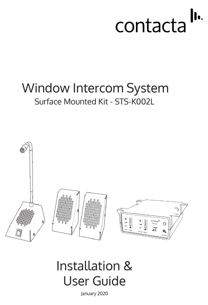
Contacta STS-K009-IP-L-B Operation manual

Installation &
User Guide
September 2021
Window Intercom System
Surface Mounted Entry System - STS-K009-IP-L-B

2
Contents
Product Overview
Components
Connections
Installation Instructions
Speaker & Microphone Kit Installation
AmplierInstallation
Speaker & Mic. Kit Installation
Hearing Loop Installation
AmplierSetup
Cleaning / Maintenance
Troubleshooting
Engineer’s Mode
3
3
4
5
6
6
7
10
11
13
14
15
Contactahasapolicyofcontinuousproductdevelopment,andthereforesmallspecication
changesmaynotbereectedinthismanual.Images,labels,packaging,accessoriesandproduct
colours are subject to change without notice.

3
Product Overview
This speech transfer system provides high quality sound across partitions or
safety screens. It includes our surface mounted entry unit with IP-55 rating,
ouropenduplexamplier,ahearingloop,andafree-standingmicrophone
andspeakerunitforsta.
The surface mounted entry unit (K009-IP) must be installed as per installation
instructions to maintain its IP-55 rating.
1. Installation and User Manual
2. Amplier
3. Hearing Loop Sticker
4. IEC Lead
5. Power Supply
6. Hearing Loop Aerial
7. Mounting Bracket
Fixing Kit:
• Adhesive Clip x 10
• No.6 x 1/2” Countersunk Screws x15
• P-Clips x6
• M3 x 24mm Universal Wall Plugs x4
• M3 x 25mm Fixing Screws x4
4
36
7
5
2
1
General Components
Speaker & Microphone Components
1. StaMicrophone
2. Surface Mounted Entry Unit
3. Screw Sticker Covers x4
2
1
3

4
Connections
StaMicrophone
Hearing Loop
Power Supply
Surface Mounted
Entry Unit
Cable Colour Amplifier Socket Amplifier Pin #
Blue Customer speaker 3-4
Brown Customer mic 14-15
Green Call/LED 9-10
Orange LEDs 11-12
Surface Mounted Entry Unit to Amplifier - Connections Colours

5
Werecommendthatinstallationiscarriedoutbyaqualiedengineer,
adhering to relevant standards.
Check the contents of the box to familiarise yourself with the components.
Installation Instructions
Negative -
or screened cable
Positive +
A toolkit recommended to install the system will include:
Trim cables if necessary (excluding the power supply)
to the required length to connect to the back of the
amplier.Bareapproximately6mmofthecableendsto
connect to the 2 pin plugs.
• Pliers
• Tape Measure
• Pencil or Marker Pen
• Torch
• Cable Ties
• Electrical Insulation Tape
• Trunking
• Screwdrivers (Flat or Blade 2.5mm
and Phillips Head PH2)
• Battery or Mains Drill
• Drillbits: 2mm, 3mm, 5mm and 7mm
• Allen Key Set
• Cable Tacking Gun (10mm)
• Wire Cutters/Strippers
Recommended Tools

6
1. Placetheamplierunderastacounter,ensuringthatitwillnotobstruct
stawhentheyaresitting.
2. Markthefourxingpointsfortheamplierunderthecounter.
3. Drillandxtheamplierinplaceusingthesuppliedscrews.
4. Installtheamplier’spowersupplyclosetoapowersocketoutletusing
thesuppliedmountingbracketandxingscrews.
Fixing points
Amplifier Installation
AmplierInstallation
LED connection or alert tone (if required)
CondenceLEDtoconrmthesystemispowered
oranalerttonefortheattentionofsta
Stamicrophoneconnection
Customer microphone connection
CondenceLED(ifrequired)forstatusalerts
and fault detection
Hearing loop aerial
Line in connection for
external audio source
Staspeakerconnection
Customer speaker connection
Power input
connection
Use power supply
through ground
supply only

7
Microphone & Speaker Installation
1. Placethestamicrophoneonthestasideof
the partition, ensuring that it does not cause an
obstructionandisasclosetostaaspossible.
It is ideally positioned no more than 300mm
awayfromthestamember.
2. Usethecablemanagementholetorunthesta
microphonecablebacktotheamplier.Ifthere
Sta
microphone
is not already a cable management hole, drill in a suitable location near
the rear of the counter.
3. Find a suitable location for surface mounted entry unit (K009-IP).
It is ideally placed at head height (approximately 1.65m) from the ground
to allow most customers to easily press and speak into it. The unit should
beinstalledagainstawalloratsurfacetoensuremaximumingress
protection.
4. Remove the x4 screws that hold the front cover of the unit together and
put these to the side.
5. Carefullyremovethefrontcoverandlocatethex4xingpointholes.The
front cover should be handled with care as it will be wired to the back
box.

8
Fixing
points
Cable
management
hole
6. Markthex4xingpointholesandcablemanagementholeonthe
mounting surface.
7. Prepare your mounting surface by installing any wall plugs necessary into
thexingpointsmarked.
Note: This kit is provided with x4 universal surface M3 x 24mm wall plugs
whichrequirea5mmpilothole.Pleaseensureappropriatexingsare
used for your intended surface.
Ensure that cables are routed into the cable management hole prior to
securing the back box to the mounting surface.
8. Usex425mmxingscrewstosecuretheboxtoitsintendedsurface
using the holes created in the step 7.
Cable
management
hole
Cable

9
9. Use the x4 removed screws from step 4 to re-attach the front cover to
the back box. Ensure the seal is in place and in good condition. Tighten
accordingly.
10. Take the x4 supplied screw cover stickers and cover the visible silver
screws (highlighted in the image below).

10
Theaerialshouldbexedunderthedesk-toporcountercentrallyonthe
custome or visitor side, one half mounted horizontally under the counter and
theotherhalfmountedvertically,facingthecustomer/visitor(asintherst
scenario below).
Position the aerial under the counter using either the provided P-clips
oranotherxingmethodofyourchoice.Seethediagrambelowfor
recommended positioning.
A is the optimum layout for a counter hearing loop.
B and C are acceptable only if A is not possible and the layout is aligned so
thatthemagneticeldwillbedirectedtowardsuser’sheadheights.
Ensure all hearing loop signage is displayed clearly.
XX
Hearing Loop Installation
A B C

11
AmplierSetup
1. Connectallgreenplugstothebackoftheamplier,followingthe
locations printed above the sockets (see page 4).
2. PowerontheamplierbypressingtheOn/Obutton.
3. Whenpoweredandinnormaloperationalmodetheamplierwilldisplay
Volume In LED 1 and Volume Out LED 1 as steady green.
4. Whentheamplierisswitchedo,allaudioismutedandnoneofthe
LEDsareilluminated.Pressinganybuttonwillturntheamplieronagain.
5. Adjust Volume In and Volume Out to a comfortable level.
6. Press and hold the Volume In (+) or (-) buttons to increase or decrease the
level. The corresponding LED bar will show the volume setting.
6. Ensure the mouse microphones are placed as close to their intended
users as possible.
7. Checktheamplierisfullyfunctionalbyensuringthered‘fault’lightis
NOT showing on the front.
8. The Amplifier is now set up.
OurWindowIntercomSystemampliersarepre-settovolumelevels
suitable for nearly all users. Should you need to adjust the Maximum
Volume,DuckingorHearingLooplevelsoutsideofthepre-setamplier
parameters, use Engineer’s Mode (see page 13).
Overview of Front Panel Buttons
Volume In (Customer/Visitor to Staff)
Increase and decrease
Volume Out (Staff to Customer/Visitor)
Increase and decrease
Settings
On/O
Setup

12
Factory Default Settings
Toreturntheamplierthefactorydefaultsettings:
1. Unplug the power supply and then reconnect it.
2. PresstheOn/ObuttonandVolumeIn(-)buttontogether,thenrelease.
3. The Volume In LED bar will have all LEDs illuminated, while the Volume
OutLEDbarwilldisplaythermwarerevisionnumberinaxedpattern
of LEDs. This indicates that default settings have been restored.
Fault Diagnosis LEDs
• Volume In LED 8 will stay red if there is a
faultwiththestamicrophone.
• Volume Out LED 8 will stay red if there is a
fault with the customer/visitor microphone.
• VolumeInLED8willashredifthereisa
fault with the loop (e.g. a broken aerial).
System Extension Cables (CABLE-STS-EX) are available in lengths of
5m, 10m, 15m and 20m. x2 sets of leads are required for the K009-IP
connectors.
Connect the plug socket into the K009-IP unit. Connect the other end to
theAmplier.
Testtoensurethesurfacemountedentryunit(K009-IP)andamplier
are functioning as per usual.
System Extension Cables

13
Ensure that your surface mounted entry unit (K009-IP) is regularly cleaned
and maintained.
Cleaning / Maintenance
To properly maintain the unit, wipe it with with a damp cloth to remove any
dirt or debris. Avoid using harsh chemicals when cleaning the unit as this may
cause damage.
Do not attempt to remove any stickers/screws from the unit unless you are a
trained Contacta engineer; doing so may void the unit warranty.
Ifyounoticeanynoticeabledamageisinictedtotheunitthenplease
contact your provider/dealer.

14
Symptom Possible Fault Action
There is no
power
detected
through the
amplifier (and
there is power at
the socket).
1) Power jack not plugged in or
faulty.
2) Plug fuse has blown.
3) Faulty power supply unit.
4)Faultyamplier.
1)Checkpowerjackisrmlyplugged
in.
2) Replace fuse. If it blows again,
replace the power supply unit.
3) Replace the power supply unit.
4)Replaceamplier.
The red LED is
illuminated on
front panel.
1) Constant red LED:
Staorcustomer/visitormicrophone
fault.
2) Red LED comes on after speech:
Induction loop fault.
1) Ensure microphone is wired
correctlyandrmlypluggedin. Try
alternative microphone to ensure
port is working.
2) Ensure induction loop connector is
wiredcorrectlyandrmlypluggedin.
I can’t hear
audio through
the induction
loop.
1) Induction loop or microphone is
disconnected.
2) Loop tester has a fault.
1 ) Check instructions for correct
connections and, if possible, check
the hearing device with a known
working hearing loop.
2) Ensure loop tester has a new set
of batteries.
I can hear
interference
through
speakers
(buzzing /
whistling /
hissing).
1) Unscreened or poorly earthed
third party equipment is being used
in close proximity.
2) Internal volume gain set to high.
3) Incorrect power supply being
used.
1)Switchoanythirdparty
equipment to identify the source of
interference.
2)Accesstheamplierengineers
mode to adjust the internal settings.
3) Ensure that our grounded power
supply unit is connected.
Amplifier goes
into feedback.
1) Internal volume gain set to high.
2) Microphone positioned too close
to speaker.
1)Accesstheamplierengineers
mode to adjust the internal settings.
2) Move the microphone to a
location further from the speaker.
Unit does not
go into power
saving mode.
1) Ambient noise in area is too high. 1)Switchoanyairconsystems,
desktop fans and/or computers to
reduce ambient noise.
Troubleshooting
If no action is successful please seek assistance from
your distributor or a Contacta installer.

15
Engineer’s Mode
Before entering Engineer’s Mode, cycle the power. To do this either:
• Switchthepoweroatthemainssocketandbackonagain
• Remove the power connector and re-insert it
To enter Engineer’s Mode, simultaneously press and release the following
buttons within 20 seconds of cycling the power:
• Settings button
• Volume In increase button
• Volume Out increase button
Number1LEDontheVolumeInwillashgreentoindicatethatyouarein
Engineer’s Mode.
Theon/oandsettingsbuttonsinEngineer’sModeoperateasfollows:
Save and exit Engineer’s Mode
Move to the next setup area
TheamplierwillautomaticallyexitEngineer’sModeifnobuttonsare
pressed for 2 minutes.
There are 3 editable setup areas in Engineer’s Mode. You will always enter
setuparea1rst.ThegreenVolumeInLEDbarwillashtoindicatewhich
setup area you are in.
Setup Area 1:
Maximum Volume Adjustment (LED 1 flashes)
Setup Area 1 allows you to adjust the Volume In and Volume Out levels to
further optimise the system for the environment in which it is installed.
Engineers Mode allows you to adjust the Volume In and Out levels, Ducking
levels and Hearing Loop levels to better suit your environment and achieve
the best possible performance.
Increase maximum
stavolumelevel
Decrease maximum
stavolumelevel
Increase maximum
customer volume level
Decrease maximum
customer volume level

16
1. Ensurethecustomer/visitorandstavolumesareturneddown.
2. Adjuststa(VolumeIn)volumetoacomfortablelevel.Pressandhold
the Volume In (+) or (-) buttons to increase or decrease the level. The
corresponding LED bar will show the volume setting.
3. Raise customer/visitor (Volume Out) volume until feedback is heard. Press
and hold the Volume Out (+) or (-) buttons to increase or decrease the
level. The corresponding LED bar will show the volume setting.
4. Lower customer/visitor (Volume Out) volume until feedback is eliminated.
Setup Area 2:
Ducking Adjustment (LED 2 flashes)
SetupArea2allowsyoutoadjusttheDuckinglevelortoturniton/o.
The ducking function is provided to reduce feedback on a window intercom
system. Feedback occurs when the overall setting of both volume controls
is too high. The ducking system works by detecting which microphone in the
conversation is being used, and temporarily reducing the volume setting.
Increase
ducking level
Decrease
ducking level
Ducking on
Duckingo
Increase drive
Decrease drive
The drive levels should be adjusted so the red LED 8 is illuminated only when
Setup Area 3:
Hearing Loop Drive Adjustment (LED 3 flashes)
SetupArea3allowsyoutoadjusttheHearingLoopDriveortoturniton/o.
Hearing loops improve communication by enabling hearing device users to
hear sound sources directly, cutting out background noise.
Hearing Loop Drive on
HearingLoopDriveo

there are peaks in the speech volume.
Iftheamplierdoesnothavealoopattached,turntheHearingLoopDriveo
as indicated in the diagram above.
17


www.contacta.co.uk
+44 (0) 1732 223900
Technical Support - Ext 5
Further information is available on our website and our YouTube channel.
WindowIntercomSTS-A31HAmplier
Setup Video
Table of contents
Other Contacta Intercom System manuals
Contacta
Contacta STS-K070 Operation manual

Contacta
Contacta STS-K002L Operation manual

Contacta
Contacta STS-K060 Operation manual

Contacta
Contacta STS-K080-IP Operation manual

Contacta
Contacta STS-K071 Operation manual
Contacta
Contacta IL-EL42-PB User manual
Contacta
Contacta STS-K020 Operation manual
Contacta
Contacta STS-K035-B Operation manual
Contacta
Contacta STS-K020 Operation manual
Contacta
Contacta STS-K001L Operation manual