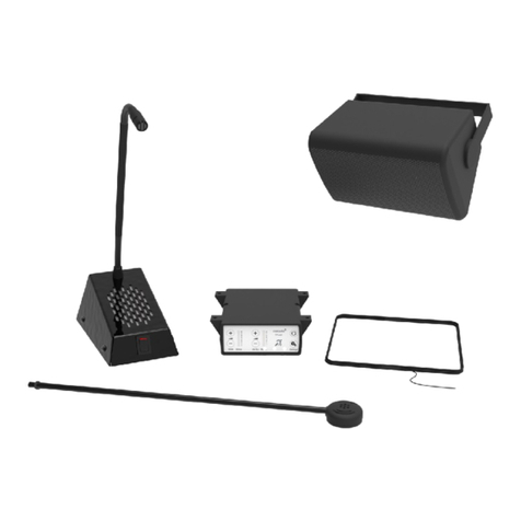
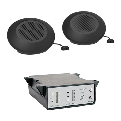
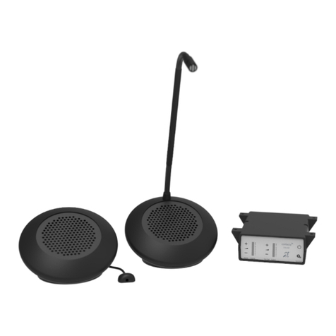
Contacta STS-K020 Operation manual

Speech Transfer System
STS-K020
December 2019
Installation &
User Guide

2
Contents
Product Overview
Installation Instructions
AmplierInstallation
Customer Microphone Installation
Customer Speaker Installation
StaSpeaker&MicrophoneInstallation
Hearing Loop Installation
AmplierSetup
Using the System
Troubleshooting
3
4
5
7
14
18
21
25
27
Contactahasapolicyofcontinuousproductdevelopment,andthereforesmallspecication
changesmaynotbereectedinthismanual.Images,labels,packaging,accessoriesandproduct
colorsaresubjecttochangewithoutnotice.

3
Contacta’sSTS-K020mayberetrottoglasswiththeopeningfroman
existingsystem.Thisproductisdesignedforinstallationatlocationssuchas
banks,postoices,theaters,andmore.
A hearing loop aerial is included to provide additional assistance for hearing
devicewearers.
Features
• Excellent sound quality
• ADA conscious
• Level 3 ballistic rated
• Sleek and modern design
Product Overview

4
AmplierInstallation
STS-A31H Speech Transfer System Amplifier
1. Placetheamplierunderthestacounter,ensuringthatitwillnot
obstructstawhentheyaresitting.
Fixing points
2. Takenoteofthecablemanagementpath.
3. Markthefourxingpointsfortheamplierunderthecounter.
4. Drillandxtheamplierinplaceusingthesuppliedscrews.
5. Please take note of the cable management path at this time

5
Customer Microphone Installation
STS-C100 Anti-Vandal Microphone with Glass Mount Kit
1. Separatethefrontandrearpolycarbonateplates.
2. Feedonesilicongasketthroughthewireconnectedtothefront
(customer-facing)polycarbonateplate.
3. Aligntheholesinthesilicongasketandthefrontpolycarbonateplate.
Screw an 8-32 2” stud into every other hole (three total) to temporary hold
thealignment.
4. Whilestandingonthecustomer-side,feedthewirecableattachedtothe
frontpolycarbonateplatethroughtheopeningoftheglassbarrier.
5. Holdthefrontpolycarbonateplateushtotheopeningintheglass
barrier and use tape to temporary secure the front polycarbonate plate to
thewindow.
6. Movetothestaside.Feedthesecondsilicongasketthroughthewire
andaligntheholestoslipontothestuds.
7. Determinethedirectionneededforthewiretubing(verticalorhorizontal).
Aligntheplatesaccordingly.
8. Measureandcutthewiretubingtothedesiredlength.Feedthewire
throughthetubinguntilreachingtheend.(Pleasenotethetubingmaybe
benttoadesiredconguration)
9. Alignandplacetherear(sta-facing)plateontothestuds.
10. Determineiftheprovidedbreak-away8-322”screwsneedtobecut

6
downbasedontheglassbarrier’sthickness.
11. Putthreeofthe8-322”screwsintotheremainingholesintheplate,
screwinginenoughtoholdallpiecestogether.
12. Removethealignmentstudsandreplacewiththeremainingthree8-322”
screws.
13. Tightenthescrewsina“star”conguration,tighteningeachscrewin
smallincrementsuntilallscrewsarecompletelytightened.
14. Securethetubinginplace.
15. Plugthewire’sconnectorintothe“CustMic”portonthebackofthe
amplier.Note:TheREDwireshouldbeontheRIGHTsideofthe
connector.

7
Customer Speaker Installation
Option 1: STS-S30 Surface Mounted Speaker (Overhead Installations)
Theoptimuminstalledheightofthisspeakeris6-8feetfromthecustomer.
Environmentswithmorebackgroundnoisemayrequirealowerinstallation.
1. Unscrewthefourscrewsonthesidesofthespeakerhousing.
2. Removethebackplatefromthespeakerhousing.
3. Find a location on the customer side directly above the glass barrier
whereinteractionswilltakeplace.Ensurethereisenoughspacetodrill
andthereisnoglassbehindthematerial.
4. Checkthecableroutetotheamplierlocationunderthecounter,noting
cablelengthandaccessthroughthecountertop.
5. Markthexingpointstomountthebackplatewhileensuringthereis
accesstoretrievethecable.
6. Drillxingpointsusingadrillbitsmallerindiameterthanthescrewsthat
willbepermanentlyinstalled.
7. Alignthebackplatewiththexingpoints.Ensurethenotchforthewireis
atthetopofthebackplate.
8. Mountthebackplateusingtheappropriatescrews/xings.
9. Attach the speaker base to the back plate with the screws previously
removedinStep1.
10. Routethecablefromthespeakerbacktotheamplierinaneatandtidy
fashion,usingcablecontainmentwhererequired.

8
11. Plugthespeakers’connectorintothe“CustSpkr”portonthebackofthe
amplier.

9
Theoptimuminstalledheightofthisspeakeris6-8feetfromthecustomer.
Environmentswithmorebackgroundnoisemayrequirealowerinstallation.
1. Find a location on the customer side directly above the glass barrier
whereinteractionswilltakeplace.Ensurethereisenoughspacetodrill
andthereisnoglassbehindthematerial.
2. Checkthecableroutetotheamplierlocationunderthecounter,noting
cablelengthandaccessthroughthecountertop.
3. Markthexingpointstomountthespeakerbracketwhileensuringthere
isaccesstoretrievethecable.
4. Drillxingpointsusingadrillbitsmallerindiameterthanthescrewsthat
willbepermanentlyinstalled.
5. Alignthespeakerbracketwiththexingpoints.
6. Mountthebackplateusingtheappropriatescrews/xings.
7. Withthecablefacingdown,sliptheboltsonthesideofthespeakerinto
thegrovesofthebracket.Adjustpositionofspeakerandtightenboltsto
secureinplace.
8. Routethecablefromthespeakerbacktotheamplierinaneatandtidy
fashion,usingcablecontainmentwhererequired.
9. Plugthespeakers’connectorintothe“CustSpkr”portonthebackofthe
amplier.
Option 2: STS-S22 Bracket Mounted Speaker (Overhead Installations)

10
Option 3: STS-S60 Surface Mounted Speaker (Counter Installations)
1. Placethespeakeronthecustomersideofthecountertop.
2. Unscrewthetwoscrewsonthesidesofthespeakerhousing.
3. Removethebracketfromthebackofthespeakerhousing.
4. Place the housing bracket on either side of the point of interaction
betweenthestaandcustomer,atleast2-3mmawayfromtheglass
barrier.
5. Marktwoxingpointsandonecablemanagementholetomountthe
housingbracketwhileensuringthereisaccesstoretrievethecable.
6. Drillxingpointsusingadrillbitsmallerindiameterthanthescrewsthat
willbepermanentlyinstalled,thendrilltheholeforthespeakercable.
Housing
xingpoints
Cable hole
Fixing points
7. Alignthehousingbracketintoposition.Feedthewirethroughthecable
hole.

11
8. Connect the speaker housing to the bracket with the previously removed
screws.
9. Routeallcablingneatlytotheamplierlocationonthestaside.
10. Plugthespeakers’connectorintothe“CustSpkr”portonthebackofthe
amplier.

12
Option 4: STS-S61 Flush Mounted Speaker (Wall/Counter Installations)
1. Ensure there is at least 2 inches of free space below the customer side of
thecountertopforthespeakerpod.
2. Ensurethereisaccesstothewiringunderthecounteronceinstalled.
3. Markthecut-outdimensionsinthediagrambelowontothecountertop.
4. Usearoutertocutouttwoareasfortheushmountedspeakerpod.
5. CutArea1indiagramtoadepthof17⁄8”.
6. CutArea2(shaded)indiagramtoadepthof1.5mm.
7. CutcornerradiustoR6inArea2.

13
8. Markthefourxingpointsasshowninthediagrambelow.
9. Drillxingpointsusingadrillbitsmallerindiameterthanthescrewsthat
willbepermanentlyinstalled.
10. Runthecablefromthespeakerthroughthecountertop.
11. Securespeakertothecounterusingthescrewsprovided.
Drilledxing
points
Speaker pod container cut-out
Fixing
points
12. Routeallthecablingneatlytotheamplierlocationonthestaside.
13. Plugthespeakers’connectorintothe“CustSpkr”portonthebackofthe
amplier.

14
StaSpeaker&MicrophoneInstallation
Option 1: STS-SU1 Staff Unit
1. Placethestaunitonthestasideofthecountertop,ensuringthatit
doesnotcauseanobstructionandisasclosetostaaspossible.
2. Usethecablemanagementholeinthecountertorunthesta
microphonecablebacktotheamplier.
If there is not already a cable management hole, drill one (or at least a ½
inchhole)inasuitablelocationneartherearofthecounter.
3. Plugtheunit’sconnectorswithBLACKandYELLOWwiresintothe“Sta
Spkr”portonthebackoftheamplier.Note:TheBLACKwireshouldbe
ontheLEFTsideoftheconnector.TheYELLOWwireshouldbeonthe
RIGHTsideoftheconnector.
4. Plugtheunit’sconnectorswithBLACK+WHITEandREDwiresintothe
“StaMic”portonthebackoftheamplier.Note:TheBLACK+WHITE
wiresshouldbeontheLEFTsideoftheconnector.TheREDwireshould
beontheRIGHTsideoftheconnector.

15
5. Thestaunitcanbeturnedonbyippingtheswitch.Whenpressed
down,the“O”positionindicatestheunitisOFF,andthe“I”position
indicatestheunitisON.

16
Option 2: STS-SJB Break Out Box with STS-Headset
3. Plugtheunit’sconnectorswithBLACK+WHITEandREDwiresintothe
“StaMic”portonthebackoftheamplier.Note:TheBLACK+WHITE
wiresshouldbeontheLEFTsideoftheconnector.TheREDwireshould
beontheRIGHTsideoftheconnector.
4. Connecttheheadphone’stwoaudiojackstothefrontoftheBreakOut
Boxintheircorrespondingports.
5. Tousetheheadphoneandmicrophone,ensurethemutebuttononthe
1. TheBreakOutBoxshouldbeinstalledunderneaththecounterusing
thescrewsprovided.Ensureitisplacedinaconvenientlocationforthe
statoaccessthemutebuttonwhilebeingmindfuloftheheadsetcable
lengthandthepositionofthestamember.
2. Plugtheunit’sconnectorswithBLACKandYELLOWwiresintothe“Sta
Spkr”portonthebackoftheamplier.Note:TheBLACKwireshouldbe
ontheLEFTsideoftheconnector.TheYELLOWwireshouldbeonthe
RIGHTsideoftheconnector.

17
frontoftheBreakOutBoxisnotpressedin.Tomute,pressthebuttonin.
5. OPTIONAL:TheSTS-SU1StaUnitmayalsobeconnectedtotheBreak
OutBox,givingstamember’stheoptiontouseeitherthestandingunit
ortheBreakOutBoxwithheadset.
1 2
1. Microphone port
2. Speaker port
a. Plugthestaunits’connectorswithBLACKandYELLOWwiresintothe
“StaSpkr”portonthebackoftheBreakOutBox.Note:TheBLACKwire
shouldbeontheLEFTsideoftheconnector.TheYELLOWwireshouldbe
ontheRIGHTsideoftheconnector
b. Plugthestaunits’connectorswithBLACK+WHITEandREDwiresinto
the“MIC”portonthesideoftheBreakOutBox.Note:TheBLACK+WHITE
wiresshouldbeontheLEFTsideoftheconnector.TheREDwireshould
beontheRIGHTsideoftheconnector.
c. TousetheSTS-SU1StaUnit,ensurethemutebuttononthesideofthe
BreakOutBoxisnotpressedinandtheStaUnitandSpeaker’sswitchis
intheONposition.Tomute,pressthemutebuttonontheBreakOutBox.

18
Hearing Loop Installation
Option 1: IL-AE96 Window Mount Hearing Loop
TheIL-AE96WindowMountHearingLoopshouldbeinstalledindoorsonthe
staside.
1. Determinethelocationofthehearingloopaerialontheglassbarrier.
Makesuretoplaceitdirectlyinfrontofwhereacustomerwillstand.Itis
recommended that the unit is placed on the bottom corners of the glass
barrierforoptimalperformance.Donotexceed2feetabovetheaverage
standingcustomer.
2. Cleantheareawithaglasscleanerandthoroughlywipedry.
3. Removethelineronthebluesheetwithafaintoutlineofthe
internationalhearingloopsignagetoexposetheadhesivebacking.
Please note that both sheets are notsolidblue.
4. Carefully attach the sheet on the glass barrier with the international
hearingloopsignagefacingthecustomer.Slowlyapplytoglassbarrier
whilesmoothingoutairbubbleswithstraight-edgedtool.
5. Removethelineronthesolidbluesheet,exposingtheadhesive.
Ensureallhearingloopsignageisdisplayedclearly.

19
6. Carefully apply the hearing loop aerial with attached cable to the
adhesiveonthesolidbluesheet.Ensurethecableisattheedgeofthe
sheet, and the wire is coming from the back side of the aerial when
applied.
7. Attach the solid blue sheet with hearing loop aerial to the sheet attached
totheglassbarrier.Slowlyapplywhilesmoothingoutairbubbleswith
straight-edgedtool.
8. Routethecablingneatlytotheamplierlocationonthestaside.
9. Plugtheloop’sconnectorintothe“Loop”portonthebackofthe
amplier.

20
Option 2: Under the Counter Hearing Loop
1. Theaerialshouldbexedunderthedeskorcountercentrallyonthe
customerside,onehalfmountedhorizontallyunderthecounterandthe
other half mounted vertically, facing the customer (see A in the diagram
below).
Position the aerial under the counter using either the provided P-clips
oranotherxingmethodofchoice.Seethediagrambelowfor
recommendedpositioning.
Aistheoptimumlayoutforacounterhearingloop.
BandCareacceptableonlyifAisnotpossibleandthelayoutisaligned
sothatthemagneticeldwillbedirectedtowardsuser’sheadheights.
2. Routethecablingneatlytotheamplierlocationonthestaside
3. Plugtheloop’sconnectorintothe“Loop”portonthebackofthe
amplier.
X
X
A B C
Other manuals for STS-K020
1
Table of contents
Other Contacta Intercom System manuals

Contacta
Contacta STS-K071 Operation manual

Contacta
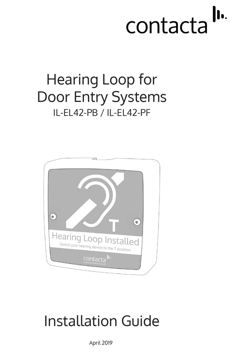
Contacta IL-EL42-PB User manual

Contacta
Contacta STS-K060 Operation manual

Contacta
Contacta STS-K080-IP Operation manual

Contacta
Contacta STS-K009-IP-L-B Operation manual

Contacta
Contacta STS-K035-B Operation manual

Contacta
Contacta STS-K001L Operation manual
Contacta
Contacta STS-K070 Operation manual

Contacta
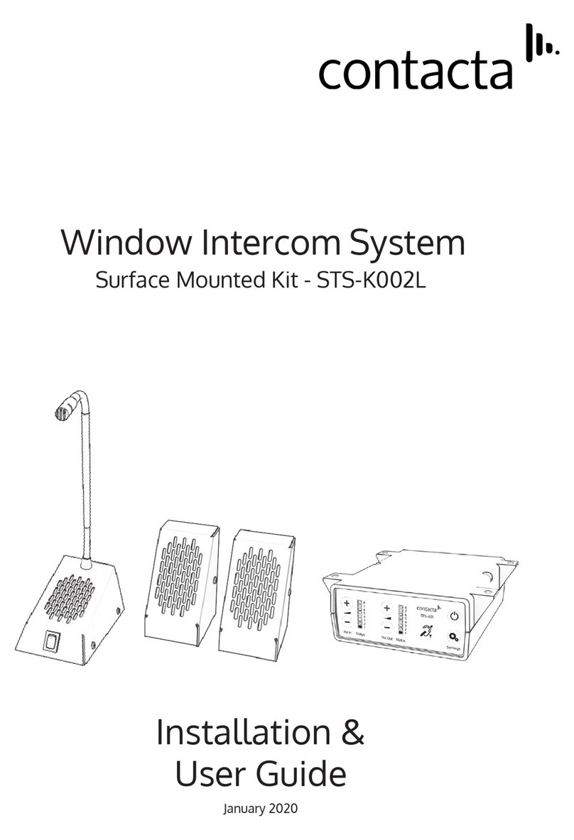
Contacta STS-K002L Operation manual
Contacta
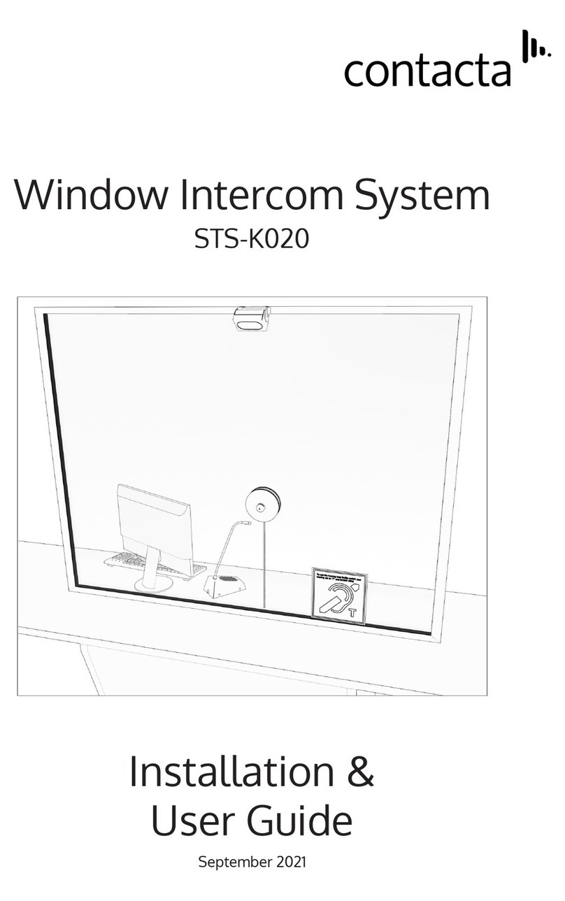
Contacta STS-K020 Operation manual