Contacta STS-K002L-G-01 Operation manual

Installation &
User Guide
June 2020
Speech Transfer System
Dual Surface Mounted System
STS-K002L-G-01 | STS-K002L-B-01

2
Contents
Product Overview
Components
Installation Instructions
AmplierInstallation
Microphone & Speaker Installation
Hearing Loop Installation
AmplierSetup
Using the System
Troubleshooting
3
3
4
5
6
7
8
10
12
Contactahasapolicyofcontinuousproductdevelopment,andthereforesmallspecication
changesmaynotbereectedinthismanual.Images,labels,packaging,accessoriesandproduct
coloursaresubjecttochangewithoutnotice.

3
Product Overview
Components
Speech transfer systems provide assistance for clear communication where
normal speech is impaired by use of glass, a security screen or other similar
barriers.
There is a hearing loop facility included, providing additional assistance for
hearingdevicewearers.
1. Installation and User Manual
2. Amplier
3. Hearing Loop Sticker
4. IEC Lead
5. Power Supply
6. HearingLoopAerial
7. MountingBracket
8. SurfaceMountedSpeakerand
Microphone x 2
Fixing Kit:
• Adhesive Clip x 10
• No.6x1/2”CountersunkScrewsx15
• P-Clips x 6
4
36
7
5
2
1
General Components
8

4
Werecommendthatinstallationiscarriedoutbyaqualiedengineer,
adheringtorelevantstandards.
Checkthecontentsoftheboxtofamiliariseyourselfwiththecomponents.
Thestamicrophoneandampliershouldbeinstalledonthestasideofthe
counter.Thecustomerspeakerandmicrophonekitsshouldbeinstalledon
thecustomersideofthecounter.
Follow all relevant instructions in the following order:
1. AmplierInstallation(seepage5).
1. Microphone&SpeakerInstallation(seepage6).
2. HearingLoopInstallation(seepage7).
3. AmplierSetup(seepage8).
4. UsingtheSystem(seepage10).
Installation Instructions
A basic toolkit recommended to install the system will include:
• Pliers
• Tape Measure
• Pencil or Marker Pen
• Cable Ties
• Electrical Insulation Tape
• Trunking
• Screwdrivers(FlatorBlade2.5mm
andPhillipsHeadPH2)
• Battery or Mains Drill
• Drillbits: 2mm, 3mm, 5mm and 7mm
• Allen Key Set
• CableTackingGun(10mm)
• WireCutters/Strippers
Recommended Tools

5
1. Placetheamplierunderthestacounter,ensuringthatitwillnot
obstructstawhentheyaresitting.
2. Markthefourxingpointsfortheamplierunderthecounter.
3. Drillandxtheamplierinplaceusingthesuppliedscrews.
4. Installtheamplier’spowersupplyclosetoapowersocketoutletusing
thesuppliedmountingbracketandxingscrews.
Fixing points
Amplier Installation
Amplier Connections
After all relevant components have been installed, connect all green plugs to
thesocketsattherearoftheamplierfollowingthelayoutdetailedbelow.
LED connection oralerttone(ifrequired)
CondenceLEDtoconrmthesystemispowered
oranalerttonefortheattentionofsta
Stamicrophoneconnection
Customer microphone connection
CondenceLED(ifrequired)forstatusalerts
and fault detection
Hearing loop aerial
Line in connection for
external audio source
Staspeakerconnection
Customer speaker connection
Power input
connection
Use power supply
through ground
supply only
AmplierInstallation

6
Microphone & Speaker Installation
1. Place the speaker and microphone pods on the customer side of the
countertop.
2. Disassemble the speaker and microphone pods on by undoing the screws
andremovingthehousing.
Surface Mounted Kit
3. Placethemountingbracketsadjacenttoeithersideofthe
pass-throughtray,atleast2-3mmawayfromthescreen.
4. Marktheeighttotalxingpointsandtwocableholestobedrilled.
5. Ensuretherewillbeaccesstoretrievethecablesanddrilltheholes.
6. Fixthespeakerandmicrophonepodstothecounter,andfeedthewires
throughthecablemanagementholes.
7. Retthehousingwithpreviouslyremovedscrews.
Fixing points
Housing
xingpoints
Cable holes
8. Repeatsteps1to7onthestasideofthecountertop.
9. Routeallcablingneatlytotheamplierlocation.

7
Theaerialshouldbexedunderthedesk-toporcountercentrallyonthe
customer side, one half mounted horizontally under the counter and the other
halfmountedvertically,facingthecustomer(asintherstscenariobelow).
Position the aerial under the counter using either the provided P-clips
oranotherxingmethodofyourchoice.Seethediagrambelowfor
recommendedpositioning.
Aistheoptimumlayoutforacounterhearingloop.
B and C are acceptable only if A is not possible and the layout is aligned so
thatthemagneticeldwillbedirectedtowardsuser’sheadheights.
Ensureallhearingloopsignageisdisplayedclearly.
XX
Hearing Loop Installation
A B C

8
AmplierSetup
Ouramplierprovidesfullopenduplexcommunicationandiscompatible
withallofourspeechtransfersystems.Itfeaturesindividualdisplaysforsta
orcustomeradjustmentsandindividualfaultlightsforeasyfaultdiagnosis.
Vol In Status
8
7
6
5
4
3
2
1
Vol Out STS-A31
CO2
contacta
Overview of Front Panel Buttons
Volume In
Increase and decrease
Volume Out
Increase and decrease
Settings
On/O
Vol In Status
8
7
6
5
4
3
2
1
Vol Out STS-A31
CO2
contacta
Vol In Status
8
7
6
5
4
3
2
1
Vol Out STS-A31
CO2
contacta
Vol In Status
8
7
6
5
4
3
2
1
Vol Out STS-A31
CO2
contacta
Save and exit engineers mode
Move to the next setup area
Beforeenteringengineersmode,cyclethepower.Todothiseither:
• Switchthepoweroatthewallsocketandbackonagain,
or,
• Removethepowerconnectorandre-insertit
To enter engineers mode, simultaneously press and release the following
buttons within 20 seconds of cycling the power:
• Settings button
• Volume In increase button
• Volume Out increase button
Theon/oandsettingsbuttonsinengineersmodeoperateasfollows:
Please note:
• Saveandexitengineersmodeaftermakinganyadjustments.
• Theamplierwillautomaticallyexitengineersmodewithoutsavingifno
buttonsarepressedfor2minutes.
Engineer’s Mode

9
Setup Area 3: Hearing Loop Drive Adjustment (LED 3 ashes)
Increase drive
Decrease drive
Vol In Status
8
7
6
5
4
3
2
1
Vol Out STS-A31
CO2
contacta
Vol In Status
8
7
6
5
4
3
2
1
Vol Out STS-A31
CO2
contacta
Vol In Status
8
7
6
5
4
3
2
1
Vol Out STS-A31
CO2
contacta
LEDs illuminate to
display loop drive
voltage
Iftheamplierdoesnothavealoopattached,turnotheredloopfaultLED
8byadjustingthedrivedowntoo.
Please note: Iftheamplierdetectsanerrorinitssettingsmemoryitwill
restoreitselftofactorydefaultsettings.
Whilstinengineersmode,thereare3editablesetupareas.Youwillalways
entersetuparea1rst.ThegreenVolumeInLEDbarwillashtoindicate
whichsetupareayouarein.
Setup Areas
Setup Area 2: Ducking Adjustment (LED 2 ashes)
Setup Area 1: Maximum Volume Adjustment (LED 1 ashes)
Increase maximum
stavolumelevel
Decrease maximum
stavolumelevel
Increase maximum
customer volume level
Decrease maximum
customer volume level
Increase
ducking level
Decrease
ducking level
Ducking on
(VolOutLED1illuminates)
Duckingo
(VolOutLED1turnso)

10
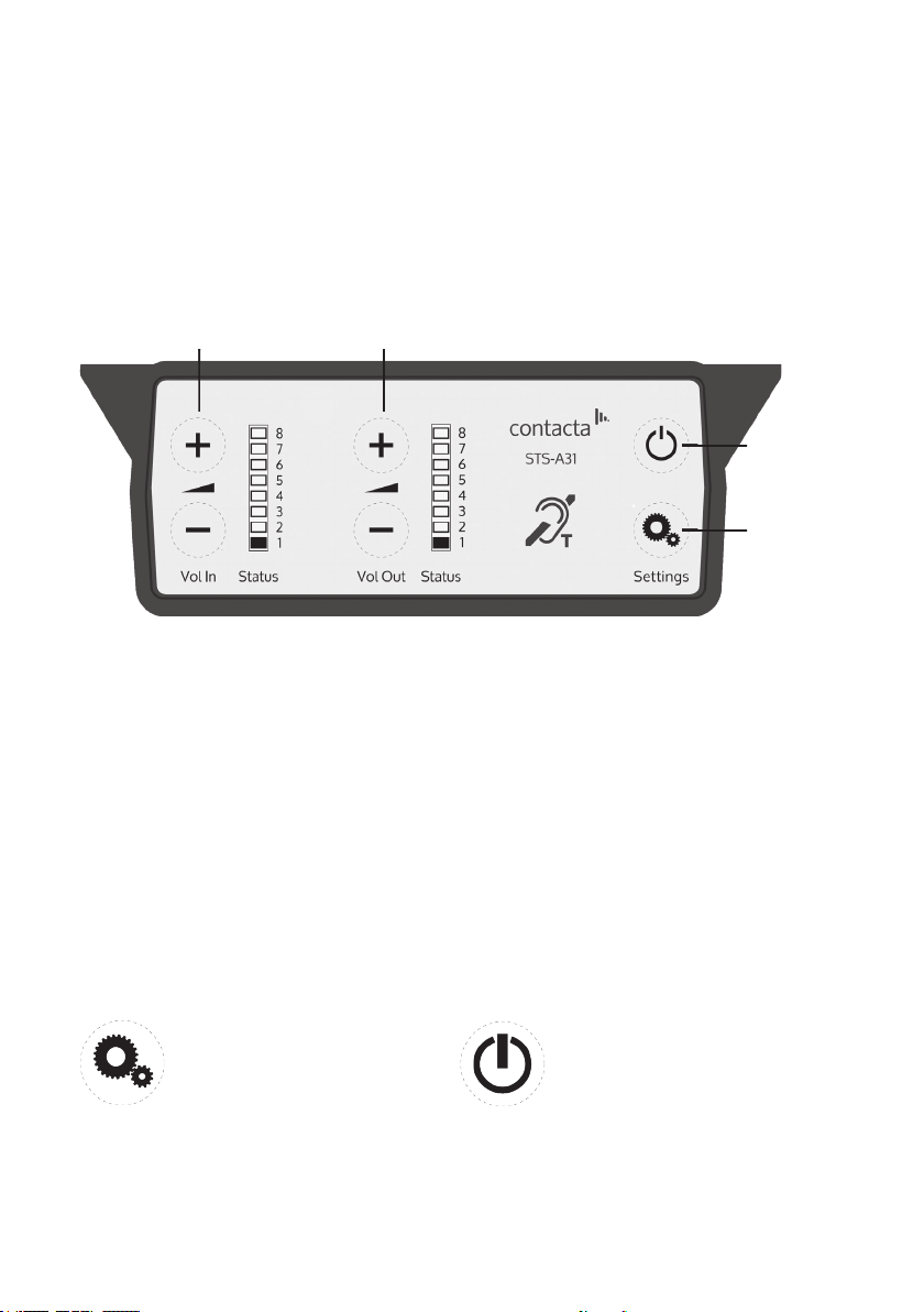
Whenpoweredandinnormaloperationalmodetheamplierwilldisplay
VolumeInLED1assteadygreen.
WhentheamplierisswitchedousingtheOn/O button, audio is muted
andLEDsarenotilluminated;pressanybuttontoturntheamplieronagain.
To adjust the sta volume level:
• PressandholdtheVolumeIn(+)or(-)buttonstoincreaseordecreasethe
level.ThecorrespondingLEDbarwillshowthevolumesetting.
To adjust the customer volume level:
• PressandholdtheVolumeOut(+)or(-)buttonstoincreaseordecrease
thelevel.ThecorrespondingLEDbarwillshowthevolumesetting.
Fault Diagnosis LEDs
• Volume In LED 8 will stay red if there is a
faultwiththestamicrophone.
• Volume Out LED 8 will stay red if there is a
faultwiththecustomermicrophone.
• VolumeInLED8willashredifthereisa
faultwiththeloop(i.e.abrokenaerial).
Using the System
For best possible performance:
1. Ensurethecustomerandstavolumesareturnedcompletelydown.
2. Adjuststavolume(VolumeIn)toacomfortablelevel.
3. Increasecustomervolume(VolumeOut)untilfeedbackisheard.
4. Decreasecustomervolume(VolumeOut)untilfeedbackisjusteliminated.
Checkthattheamplierisfullyfunctionalbyensuringthered‘fault’light
isNOTdisplaying.
5. Ifthereisinsuicientvolumeevenafteryouhaveadjustedthevolume
controls,enterengineersmodeandraisemaxvolumesettings.Exit
engineersmodeandrepeatinitialsetup.
6. Thesystemisnowreadytouse.

11
Factory Default Settings
Toreturntheamplierthefactorydefaultsettings:
1. Unplugthepowersupplyandthenreconnectit.
2. PresstheOn/ObuttonandVolumeIn(-)buttontogether,thenrelease.
3. The Volume In LED bar will have all LEDs illuminated, while the Volume
OutLEDbarwilldisplaythermwarerevisionnumberinaxedpattern
ofLEDs.Thisindicatesthatdefaultsettingshavebeenrestored.

12
Symptom Possible Fault Action
There is no
power
detected
through the
amplier (and
there is power
at the socket).
1)Powerjacknotpluggedinor
faulty.
2)Plugfusehasblown.
3)Faultypowersupplyunit.
4)Faultyamplier.
1)Checkpowerjackisrmlyplugged
in.
2)Replacefuse.Ifitblowsagain,
replacethepowersupplyunit.
3)Replacethepowersupplyunit.
4)Replaceamplier.
The red LED is
illuminated on
front panel.
1) Constant red LED:
Staorcustomermicrophonefault.
2)Red LED comes on after speech:
Inductionloopfault.
1)Ensuremicrophoneiswired
correctlyandrmlypluggedin. Try
alternative microphone to ensure
portisworking.
2)Ensureinductionloopconnectoris
wiredcorrectlyandrmlypluggedin.
I can’t hear
audio through
the induction
loop.
1)Inductionloopormicrophoneis
disconnected.
2)Looptesterhasafault.
1)Checkinstructionsforcorrect
connections and, if possible, check
the hearing device with a known
workinghearingloop.
2)Ensurelooptesterhasanewset
ofbatteries.
I can hear
interference
through
speakers
(buzzing /
whistling /
hissing).
1)Unscreenedorpoorlyearthed
third party equipment is being used
incloseproximity.
2)Internalvolumegainsettohigh.
3)Incorrectpowersupplybeing
used.
1)Switchoanythirdparty
equipment to identify the source of
interference.
2)Accesstheamplierengineers
modetoadjusttheinternalsettings.
3)Ensurethatourgroundedpower
supplyunitisconnected.
Amplier goes
into feedback.
1)Internalvolumegainsettohigh.
2)Microphonepositionedtooclose
tospeaker.
1)Accesstheamplierengineers
modetoadjusttheinternalsettings.
2)Movethemicrophonetoa
locationfurtherfromthespeaker.
Unit does not
go into power
saving mode.
1)Ambientnoiseinareaistoohigh. 1)Switchoanyairconsystems,
desktop fans and or computers to
reduceambientnoise.
Troubleshooting
If no action is successful please seek assistance from
yourdistributororaContactainstaller.


Contact your local
distributor for further
information.
www.contacta.co.uk
This manual suits for next models
1
Table of contents