Contec Alpha User manual

ALPHA®
Floor Grinder
Instruction manual (USA)

Instruction manual ALPHA
®
- 2 -
CONTEC
®
GmbH Hauptstrasse 146, 57518 Alsdorf, Deutschland/ Germany/ Allemagne © CONTEC
®
2011
info@contecgmbh.com, www.contecgmbh.com
Index
1. EU-Declaration of Conformity ...3
2. Machine applications ...4
3. Technical data ...4
4. Application of tools ...4
5. Safety rules for the operation of the floor grinder ...5
6. Operation ...6
7. Changing of tools ...7
8. Appendix ...7

Instruction manual ALPHA
®
- 3 -
CONTEC
®
GmbH Hauptstrasse 146, 57518 Alsdorf, Deutschland/ Germany/ Allemagne © CONTEC
®
2011
info@contecgmbh.com, www.contecgmbh.com
Declaration of Conformity according to EN ISO/IEC 17050-1
EC-Declaration of Conformity
Month.Year: .
For the machine described below
Product denomination:
Model:
Serial number:
Floor Grinder
Alpha
®
Herewith we declare, that the machine is complying with all the essential requirements of the
Machine Directive 2006/42/EC of the EUROPEAN PARLIAMENT of the 17th of Mai 2006
The person authorized to compile the relevant technical documentation (According to Appendix II Nr.
1. A. Nr. 2, 2006/42/EG):
Name, Surname: Greb, Johannes
Function: Technical Manager
Address: Neuer Weg 17, 57518 Alsdorf, Germany
More information on the compliance with the directive is contained in Appendix 1.
This Declaration is given by the manufacturer:
Name: Contec
®
Maschinenbau & Entwicklungstechnik GmbH
Address: Hauptstraße 146, 57518Alsdorf, Deutschland/Germany
Given by:
Name, Surname: Greb, Johannes
Function: Technical Manager
Alsdorf, 22.12.2010
Place/Date Signature
Appendix 1 of the Declaration of Conformity
Month.Year: .
For the machine described below
Product denomination:
Model:
Floor Grinder
Alpha
®
Herewith we declare, that the machine is complying with all the essential requirements of the:
Directive 2004/108/EC of the EUROPEAN PARLIAMENT of the 15th of December 2004 on
Electromagnetic Compatibility
Directive 2006/42/EC of the EUROPEAN PARLIAMENT of the 17th of Mai 2006
Harmonised Standards used:
EN 12100 - 1 „Safety of Machinery – Basic concepts“
EN 12100 - 2 „Safety of Machinery – Technical principles”

Instruction manual ALPHA
®
- 4 -
CONTEC
®
GmbH Hauptstrasse 146, 57518 Alsdorf, Deutschland/ Germany/ Allemagne © CONTEC
®
2011
info@contecgmbh.com, www.contecgmbh.com
2 Machine applications
Grinding of horizontal, dry floors such as concrete and steel surfaces with or without a
coating and asphalt using CONTEC
®
grinding tools. The use of the machine outside is only
possible in dry weather.
3 Technical data
Grinding width 230 mm (9 in)
Width 30 cm (12 in)
Length 60 cm (24 in)
Height 51 cm (20 in)
Weight 42 kg (93 Ibs)
Speed of grinding head 1680 rpm
Hose ¯50 mm (1.97 in)
Average value of acceleration a
hv
* 9.6 m/s
2
Noise level L
wa
* 100 dB(A)
Noise level Leq * 90 dB(A)
* Data: VÜA Verein zur Überwachung technischer Anlagen e.V.
4 Application of tools
4.1 General applications
Tool
Application Diamond PCD
Grinding of plain floors,
- Smooth surface
- Semi rough surface
- Rough surface
A
A
A
C
B
A
Levelling of uneven surfaces
- Smooth surface
- Semi rough surface
- Rough surface
A
A
B
A
A
A
Levelling of Steps, corners, joints etc. B A
Renovation
Repair
Faults in concrete
A
A
A
B
B
B
Grinding of
- Hard concrete
- Oily and greasy floors
- Painted floors
- Epoxy coatings
A
A
A
A
B
B
A
A
Removal of floor surfaces up to 5 mm A C
Removal of carpet and tile glue C A
Grinding of asphalt B A
A Suitable B Less suitable C Unsuitable

Instruction manual ALPHA
®
- 5 -
CONTEC
®
GmbH Hauptstrasse 146, 57518 Alsdorf, Deutschland/ Germany/ Allemagne © CONTEC
®
2011
info@contecgmbh.com, www.contecgmbh.com
4.2 Application of diamond discs
Grinding of:
Description: Colour:
Hard floors CS16 / PCD grit silver
Normal concrete CS40 / VS2 Blue / red
Aggressive concrete CA1 / CA2 Brown / green
Terrazzo MBC line
Epoxy / PU glue PCD plate and grit silver
5 Safety rules for the operation of the floor grinder
Attention! The ALPHA
®
floor grinders are constructed according to existing safety rules
and regulations. These technical precautions should not be removed or changed
under any circumstances. While operating the machines the following points
should also be kept in mind:
1. The grinders should always be operated with all safety covers and technical precautions.
2. During transport, cleaning, repair or maintenance the grinder must be disconnected from
the mains. That also applies to the changing of tools.
3. The safety ring (Diagram No. 17) can only be removed while operating the machine
directly against the wall. While operating the machine without the safety ring dust can be
generated. In this case the operator must wear a mask. In all other cases the grinder must
be operated with the safety ring.
4. The operator should never leave the machine unattended during operation.
5. Before leaving the machine all rotary parts should be brought to a stand still. Electric
models must be disconnected from the mains. Make sure that the machine cannot roll or
move by itself.
6. After any maintenance and adjustment all safety covers must be reattached.
7. Ear protectors must be worn.
8. Eye protectors must be worn.
9. Safety shoes with steel caps must be worn.

Instruction manual ALPHA
®
- 6 -
CONTEC
®
GmbH Hauptstrasse 146, 57518 Alsdorf, Deutschland/ Germany/ Allemagne © CONTEC
®
2011
info@contecgmbh.com, www.contecgmbh.com
10. In the event of a large amount of dust during operation, connect a dust collector to the
grinder.
11. Depending on the floor (floor coating) grinding can produce gases. The operator must be
held responsible if these generated gases are dangerous and if protection is necessary.
Grinding floors containing asbestos is especially dangerous and can cause health
problems. Special masks must be worn which keep the breathing air clean. A dust
collector must be used and should be equipped with filters suitable for asbestos dust.
12. The floor must be brushed before grinding because loose material could get into the tools
and fly away. Anchor screws and bolts coming out of the floor can also be seen better if
the floor is clean. If the grinding head hits a anchor screw or bolt then serious damage can
be caused to the machine or grinding head.
6 Operating
Disconnect the grinder from the power supply!
After mounting the appropriate tools, the operation of the grinder can begin.
Adjust the grinder by loosening the screws of the rear wheel swing (Appendix diagram No. 3)
and changing its position in the slots so that the motor axis is 90° level to the floor. Tighten
the screws again. Connect the grinder to the mains. Lift the tool from the floor by tilting the
machine onto its back wheels. Switch the motor on.
Attention, when switching on the motor, beware the machine jumps slightly.
After the motor has reached full speed, place the grinding head carefully on the floor. If the
machine is correctly adjusted (see above) it is easy to move across the floor. If the machine
pulls to the left or right, the machine has to be re-adjusted by changing the position of the rear
wheel swing (see above).
Attention: Never switch the motor on while the grinding head is on the floor.
Dust emission should be prevented by connecting a dust collector.
Before finishing the grinding process the machine must be switched off and the tools have to
be brought to a stand still by letting them touch the floor. Disconnect from the power supply.

Instruction manual ALPHA
®
- 7 -
CONTEC
®
GmbH Hauptstrasse 146, 57518 Alsdorf, Deutschland/ Germany/ Allemagne © CONTEC
®
2011
info@contecgmbh.com, www.contecgmbh.com
7 Changing of the tools
Attention: Before working on the grinder bring the motor to a total stand still and
disconnect from the power supply.
Attention: Tools can be hot after use.
-Tilt the machine onto the back wheels and rest it on the handlebar.
-All tools discs are fixed with three Allen screws to the tool bracket. Appendix „Alpha
®
tools“ No. 10.
-Remove the screws with an 8mm Allen key.
-Check the grinding tools for wear and tear for the next application.
-If necessary remove the diamond / tool plates. Each plate is held by 3 M8 screws.
-Fix new tools according to the appendix „Alpha
®
tools“.
-Adjust the different heights of the tools by changing the position of the rear wheel swing
(see chapter 6 Operating). The motor axis of the grinder has to be 90° level to the floor.
8 Appendix
Diagrams
Tools
Part list


ALPHAStückliste/ PartsList
Artikel-Nr. / Part-No.
Description 1
Description 2
D-Nr
WeightKG
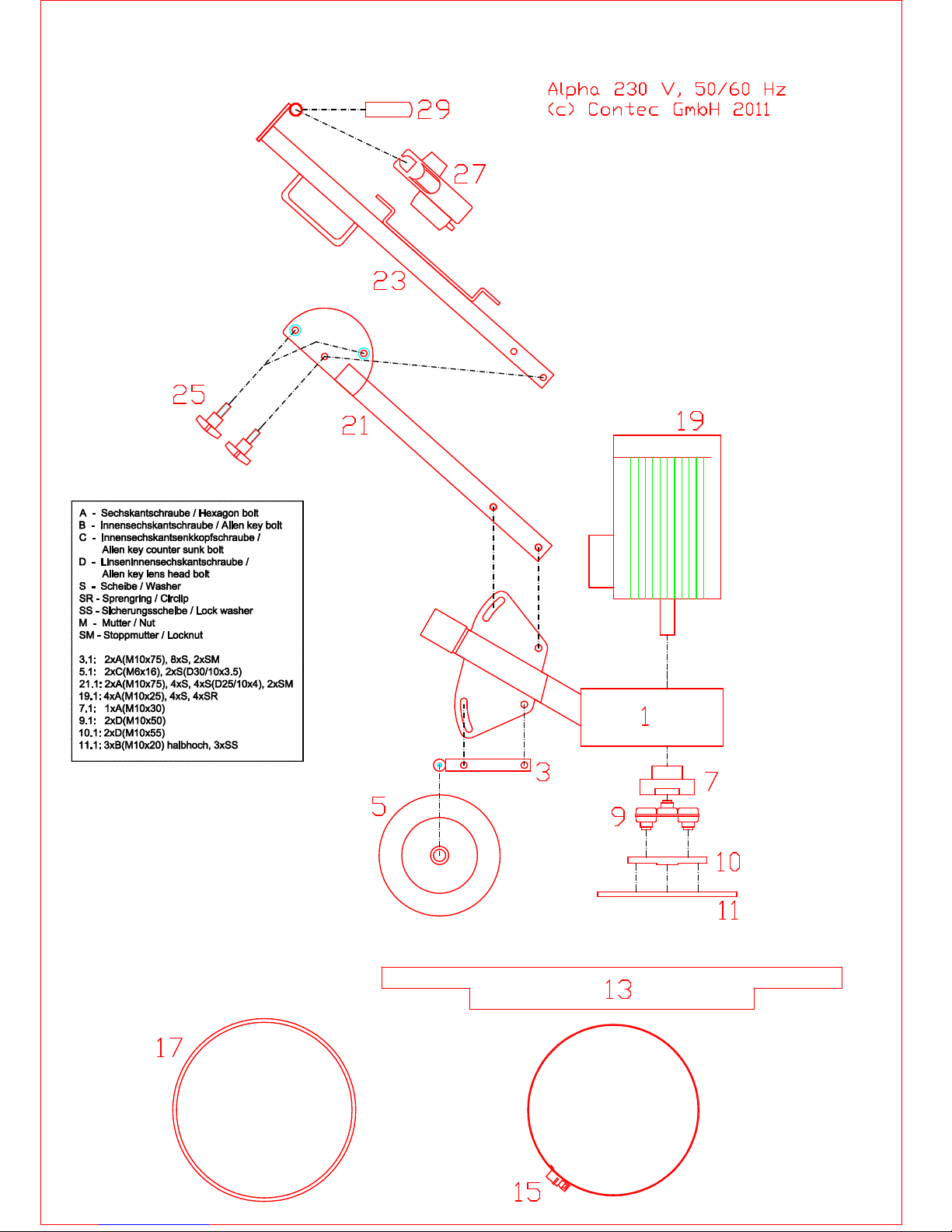
04-10-01-00 Grinding Head FrameAlpha 1 6,10
04-10-04-01 RearSwing ArmAlpha 3 1,00
80-20-52-22 RearWheelAlpha 5 1,45
18-17-06-01 Bracket forCoupling Alpha 7 1,12
90-25-10-01 RubberCoupling ForDriveAlpha 9 0,50
04-10-05-01 Bracket forPlatesAlpha 11 2,40
70-23-76-70 RubberSealing Alpha 13 0,35
90-27-03-01 ClampAlpha 15 0,21
70-23-81-50 Dustring Alpha 17 0,20
55-03-02-18 Motor1,8KVA, 230 Volt, 50 HZ, Omega 19 23,80
55-03-11-15 Motor1,5KVA, 110 Volt, 50 HZ Omega 19 15,00
04-10-02-01 BottomHandleAlpha 21 0,75
04-10-03-00 Top HandleAlpha 23 2,10
04-10-03-00-US Top HandleAlpha GBand USVersion 23 2,10
60-30-10-30 HandlescrewM10-25 Alpha 25 0,05
50-20-203-742 SwitchforAlpha 27 0,85
70-21-120-90 RubberGripAlpha 29 0,03
18-21-C1 Diamond PlateC1 Yellow 51 0,26
18-21-C2 Diamond PlateC2 Aubergine 51 0,26
18-21-CA1 Diamond PlateCA1Brown 51 0,26
18-21-CA2 Diamond PlateCA2Green 51 0,26
18-21-CS06 Diamond PlateCS06 Red 51 0,26
18-21-CS16 Diamond PlateCS16 Silver 51 0,26
18-21-CS40 Diamond PlateCS40 Blue 51 0,26
18-21-CS6/16 Diamond PlateCS6/16 Gold 51 0,26
18-21-MBC0 Diamond PlateMBC0 Brownround 51 0,26
18-21-MBC0+ Diamond PlateMBC0+Silverround 51 0,26
18-21-MBC1 Diamond PlateMBC1 Black round 51 0,26
18-21-MBC2 Diamond PlateMBC2 Green round 51 0,26
18-21-MBC3 Diamond PlateMBC3 Blue round 51 0,26
18-21-MBC4 Diamond PlateMBC4 Yellowround 51 0,26
18-21-PKD-S Diamond PlatePCD inSegment 51 0,26
18-10-29-11 Plateforpolishing Dotts 55 0,20
18-21-120-N Resignbond Wet Grid120 Black 57 0,09
Seite1von 2

ALPHAStückliste/ PartsList
18-21-120-T Resignbond Dry Grid120 Black 57 0,09
18-21-1800-N Resignbond Wet Grid1800 Blue 57 0,09
18-21-1800-T Resignbond Dry Grid1800 Blue 57 0,09
18-21-220-N Resignbond Wet Grid220 Red 57 0,09
18-21-220-T Resignbond Dry Grid220 Red 57 0,09
18-21-3000-N Resignbond Wet Grid3000 Grey 57 0,09
18-21-3000-T Resignbond Dry Grid3000 Grey 57 0,09
18-21-30-N Resignbond Wet Grid30 Brown 57 0,09
18-21-30-T Resignbond Dry Grid30 Brown 57 0,09
18-21-400-N Resignbond Wet Grid400 Yellow 57 0,09
18-21-400-T Resignbond Dry Grid400 Yellow 57 0,09
18-21-5000-N Resignbond Wet Grid5000 Pink 57 0,09
18-21-60-N Resignbond Wet Grid60 Green 57 0,09
18-21-60-T Resignbond Dry Grid60 Green 57 0,09
18-21-800-N Resignbond Wet Grid800 White 57 0,09
18-21-800-T Resignbond Dry Grid800 White 57 0,09
04-10-05-02 Bracket forSandpaperAlpha 59 2,60
23-16-01-08 FlailsforGrinderHead Tipped Tungston Carbide Omega/Alpha 65 0,03
23-16-02-08 FlailsforGrinderHead Full Tungston Carbide Omega/Alpha 67 0,04
04-10-01-01 Dustring Alpha 0,00
04-10-01-02 Dustring Alpha 0,00
04-10-01-03 Dustring Alpha 0,00
04-10-03-03 0,00
04-10-06-00 GrinderHead forFlailsfor12 Axis Alpha 0,00
04-17-06-01 Bracket forCoupling Alpha 1,12
51-10-0-25-US SwitchMotorProtectiveAlpha 110 Volt England 0,00
51-10-10-00 SwitchBoxForMotorProtectiveAlpha 110 Volt England 0,00
51-20-30-05 Undervoltage Switch110 V50 HZ Alpha England 0,00
543-204 CableRing 6mm Alpha 0,00
55-03-11-11-US Motor1,1KVA, 115 Volt, 60 HZ ALPHAUS 15,00
Seite2von 2
Other manuals for Alpha
4
Table of contents
Other Contec Grinder manuals
Popular Grinder manuals by other brands

Woodstar
Woodstar wg 08 Translation from the original instruction manual

Parkside
Parkside PWS 125 F5 Translation of the original instructions

Scheppach
Scheppach OSM100 Translation of original instruction manual

Grizzly
Grizzly G1062 instruction manual

Hitachi
Hitachi G13SC2 - 125mm Grinder 1200W Back Handle... parts list

Parkside
Parkside PFBS 9.6 V - 6 manual