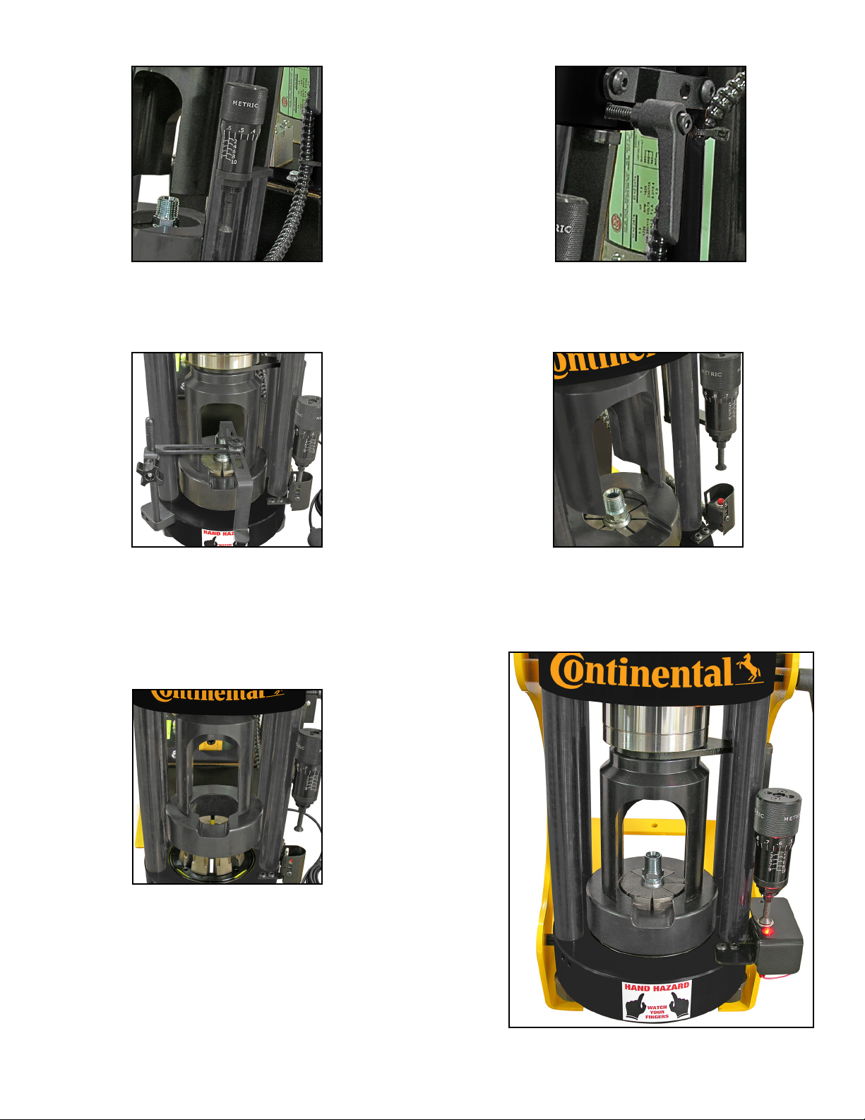
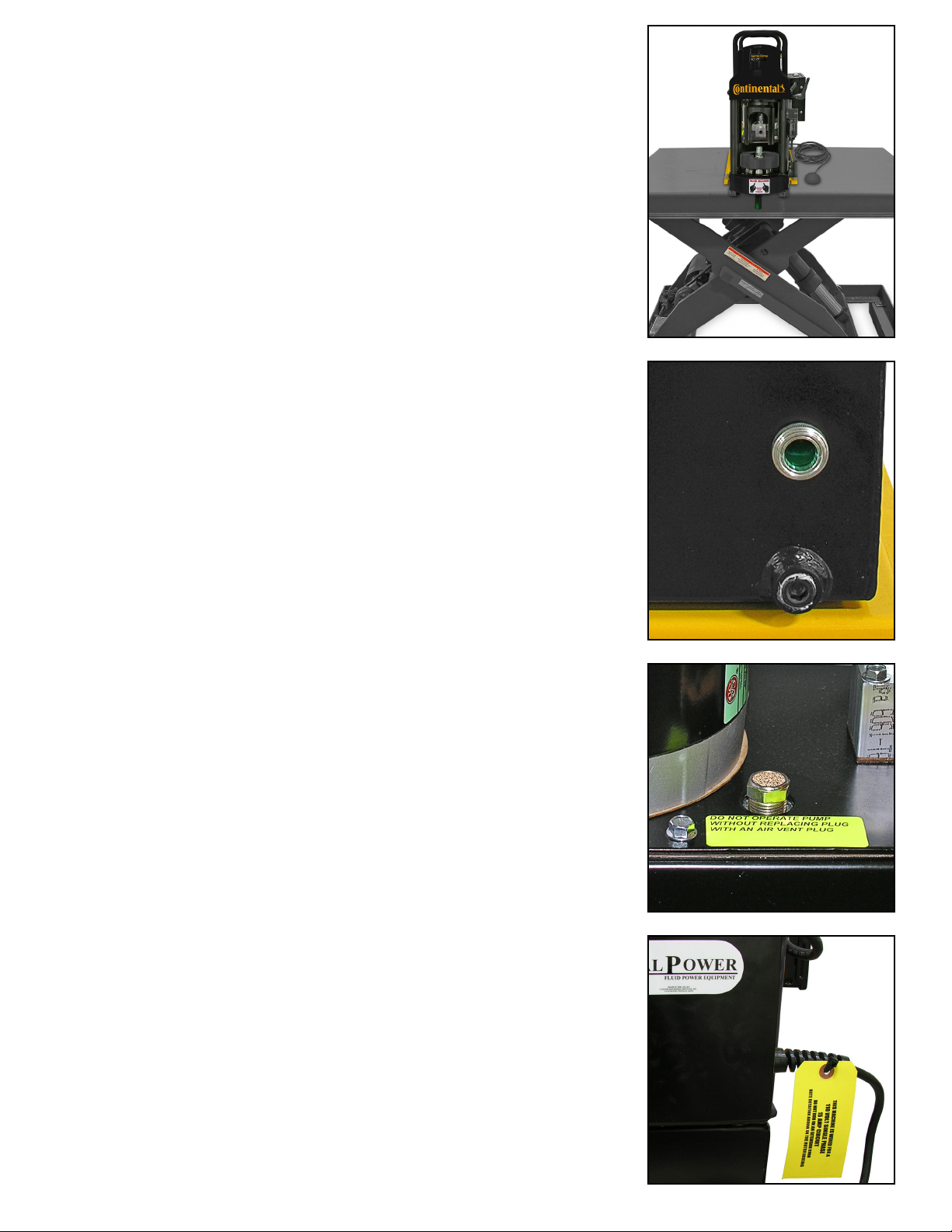
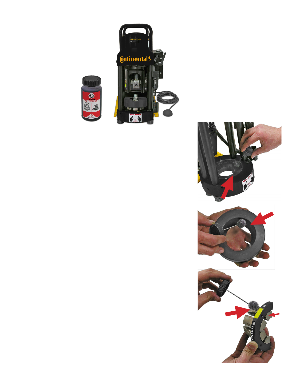
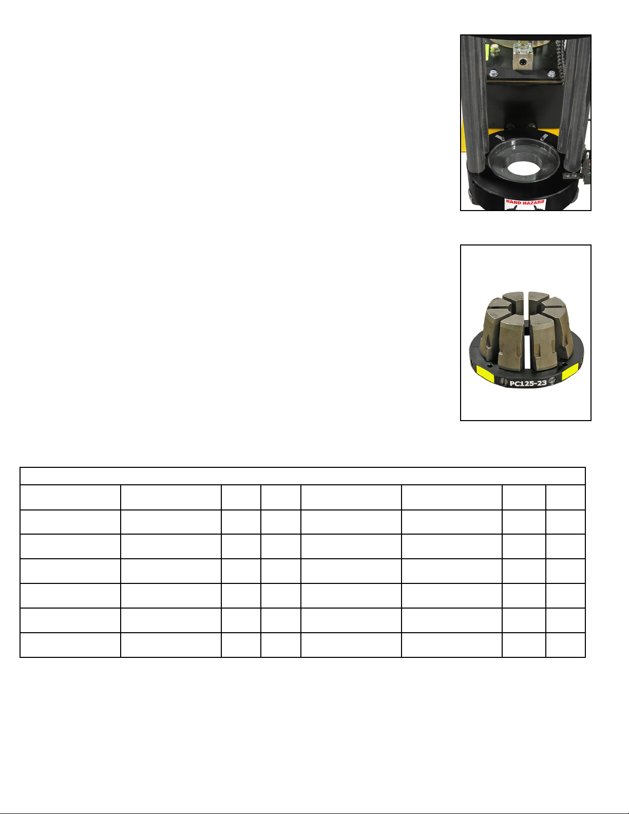
Continental Refrigerator Perma-Crimp PC125 User manual

Perma-Crimp™Hydraulic Hose Crimpers
PC125 and PC125M Operators Manual
www.continental-industry.com
2PC125 and PC125M Operators Manual
2
PC1
C1
25
an
and
nd
PC
C
125
M O
O
pe
per
ators Man
ual
al
Hydraulic Hose Crimpers
PC125 and PC125M Operators Manual
www.contitech.us

• READ INSTRUCTIONS AND IDENTIFY ALL COMPONENT PARTS BEFORE USING CRIMPER.
• CRIMPER CAN PRODUCE 60 TONS OF FORCE. KEEP BOTH HANDS AWAY FROM PINCH POINTS.
• CONSULT THE CONTINENTAL CONTITECH CRIMP SPECIFICATION MANUAL FOR CORRECT
CRIMPER SETTINGS AND CRIMP MEASUREMENTS.
• ALWAYS WEAR EYE PROTECTION.
SAFETY PRECAUTIONS
PC125 / 125M Safety Precautions
2
MODELS COVERED
This manual is applicable to dierent variations of the PC125 Series and PC125M Series Crimpers.
Crimping, calibration and repair procedures are similar for both models.
Equipment Warning
Proper assembly of Continental ContiTech hose and ttings
Continental ContiTech hose, ttings and crimping equipment work together to provide an ecient and reliable hose
connection. Continental ContiTech hose and ttings are part of an engineered system and are to be used in accor-
dance with Continental ContiTech specications. Using non-Continental ContiTech components may produce an
assembly that does not meet rated performance. Continental ContiTech does not warrant, expressly or by impli-
cation, hose assemblies that do not incorporate Continental ContiTech hose and ttings, or are not crimped
in accordance with Continental ContiTech process specications.
Buyers may elect to attach additional or non-standard parts or equipment, or to use dierent manufacturing specica-
tions as necessary to meet the requirements of the buyer or the customer’s application. In such cases, the buyer has
sole responsibility to qualify the hose for the applications as necessary to ensure performance capability.
For guidance in the assembly of Continental ContiTech hose and couplings, please refer to the Continental ContiTech
Crimp Specications Manual. Information in this manual is believed to be accurate, but is not warranted and is subject
to change without prior notice. For the most current product information, check the Continental ContiTech website at
www.contitech.us.
For technical assistance, call customer service at 1-800-235-4632.

Table Of Content
PC125 / PC125M SAFETY PRECAUTIONS-----------------------------------------------------------------------------------------------------------2
PC125 / 125M EQUIPMENT WARNING-----------------------------------------------------------------------------------------------------------------2
PC125 / PC125M SPECIFICATIONS----------------------------------------------------------------------------------------------------------------------4
PC125 / PC125M COMPONENT IDENTIFICATION---------------------------------------------------------------------------------------------------5
AVAILABLE ACCESSORIES FOR PC125 / 125M SERIES CRIMPERS-----------------------------------------------------------------------6
PC125 / PC125M FEATURES------------------------------------------------------------------------------------------------------------------7
PC125 / PC125M QUICK START GUIDE-----------------------------------------------------------------------------------------------------8
PC125 / PC125M LUBRICATION PROCEDURE-----------------------------------------------------------------------------------------------------9
PC125 / PC125M CRIMPING PROCEDURE------------------------------------------------------------------------------------------10
PC125 CALIBRATION CHECK-------------------------------------------------------------------------------------------------------------------------15
PC125M CALIBRATION CHECK----------------------------------------------------------------------------------------------------16
PC125 DRAWER / STAND ASSEMBLY-----------------------------------------------------------------------------------------17
TROUBLESHOOTING-----------------------------------------------------------------------------------------------18
PART NUMBERS-----------------------------------------------------------------------------------------------------------19
3

PC125 Crimper Series PC125M Crimper Series
PC125 / 125M Specications
D160 SERIES / D165 SPECIFICATIONS
4
Die Series-------------------------------------------------------------------------------------------------------------------------PC125 Series
Maximum Cylinder Force---------------------------------------------------------------------------------------------------------------60 Ton
Maximum Hose Diameter (2 Wire)----------------------------------------------------------------------------------------------1 1/4 Inch
Maximum Hose Diameter (4 Wire)----------------------------------------------------------------------------------------------1 1/4 Inch
Maximum Hose Diameter (6 Wire)---------------------------------------------------------------------------------------------------1 Inch
Crimper Depth - PC125 Series-------------------------------------------------------------------------------------------------22.5 Inches
- PC125M Series-------------------------------------------------------------------------------------------------17 Inches
Crimper Width - PC125 Series----------------------------------------------------------------------------------------------------13 Inches
- PC125M Series --------------------------------------------------------------------------------------------10.25 Inches
Crimper Height - PC125 Series------------------------------------------------------------------------------------------------22.5 Inches
- PC125M Series------------------------------------------------------------------------------------------------21 Inches
Weight - PC125 Series----------------------------------------------------------------------------------------------------------------140 Lbs
- PC125M Series---------------------------------------------------------------------------------------------------------------72 Lbs
Pump - PC125 Series------------------------------------------------------------------------------------------------------------------Electric
- PC125M Series----------------------------------------Pump Not included - Manual, Pneumatic, or Electric Available
Pump HP - PC125 Series-------------------------------------------------------------------------------------------------------1 HP (110V)
Reservoir Capacity - PC125 Series-----------------------------------------------------------------------------------------------1 Gallon
Oil Type---------------------------------------------------------------------------------------------------------------ISO Viscosity Grade 46
Electric Power Requirement - PC125 Series-----------------------------------------------------------------------------110V-15 Amp

PNEUMATIC START/STOP SWITCH
60 TON HYDRAULIC CYLINDER
REMOVABLE PUSHER
W/ MAGNETS
REMOVABLE PUSHER
W/O MAGNETS
CONTINENTAL QR CODE
CONTINENTAL QR CODE
110 VOLT VALPOWER®HYDRAULIC PUMP
CALIBRATION
ADJUSTMENT SCREW
HIGH STRENGTH FRAME
QUICK DISCONNECT
ELECTRICAL CORD
1 GALLON RESERVOIR
VOLTAGE TAG
PC125 DIE SET
PC125 DIE SET
NOTCHED
COMPRESSION RING
MICRO-CRIMP ADJUSTER
AUTOMATIC STOP SWITCH
POWER SWITCH
RETRACTION STOP
ELECTRICAL ENCLOSURE
PC125 CRIMPER SERIES
PC125M CRIMPER SERIES
RETRACTION STOP
PC125 / 125M Component Identication
MICRO-CRIMP ADJUSTER
CALIBRATION
ADJUSTMENT SCREW
LED INDICATOR LIGHT
NOTCHED
COMPRESSION RING
NOTCHED
COMPRESSION RING
PC125 DIE SERIES
PRESSURE PLATE
5

Coupling Stop
(Included only with PC125)
CRIMPX Die Lubricant Oil:
4 oz bottle with dauber cap
(Included)
Die Removal Magnet
(Included)
PC125 Drawer/Stand
(Included only with PC125-Skits Series Crimpers)
Available PC125 Die Series
Removable Pusher
(Included)
PC125 w/ magnets
PC125M no magnets
ValPower® Hand Pump
10,000 psi (Optional)
ValPower® Pneumatic Pump
10,000 psi (Optional)
ValPower® Electric Pump (Optional)
MANUAL, PNEUMATIC, AND ELECTRIC POWER SOURCES ARE AVAILABLE FOR
THE PC125M CRIMPER SERIES
Notched Compression Ring
(Included)
Vent Plug
(Included)
Metric Micrometer
(Included)
Pressure Plate
(Included)
Available Accessories For PC125 / 125M Series Crimpers
Pneumatic Pendent Switch
(Included)
6

PC125 / PC125M Features
7
Micrometer style adjustment permits crimping
a wide variety of hose and ttings, and is fully
adjustable for a precise crimp.
Adjustable Retraction Stop limits ram retraction to
only the amount required to remove the hose and
coupling saving time on multiple crimps.
Automatic stop switch shuts the pump o
when the crimp cycle is complete.
(PC125 series only).
LED Indicator light will warn the operator
when the crimp cycle is complete.
(PC125M series only).
An easily removable Coupling Stop
makes repetitive crimps faster by not
having to visually align the tting before
each crimp.
Powerful magnets in the pusher retract the
notched compression ring with ram on each
cycle. This permits the operator to operate the
crimper essentially “hands free”.
(PC125 series only).

• Mount the crimper on a sturdy workbench in a well-lit area. Workbench
should be able to support the crimper weight of 140 lbs for PC125 and 72
lbs for PC125M.
Note: The PC125 series can be mounted on the PC125 Drawer/Stand and
bolted onto the workbench. (See detailed instructions included with PC125
drawer/stand).
• The crimper should be mounted close enough to the edge of the
work surface so that hose will not contact the bench or work surface
while crimping. There must be enough clearance for the hose to align
perpendicular with the cone base, or the dies will not seat properly and the
crimps will not be accurate.
• Always check oil level in the PC125 pump, should be 1-1/2 to 2 inches
below the vent plug when the cylinder is in the retracted position and should
be visible in the sight glass window of the pump reservoir.
• If oil needs to be added use ISO 46 weight hydraulic oil.
• Oil can be drained from the rear oil port of the reservoir.
• If using an optional power unit for the PC125M, follow the
manufacturer’s recommendation for proper setup and use. A 10,000 psi
hose and quick disconnect tting has been included with the crimper to
connect an optional
power unit to the PC125M cylinder port.
• Check to be certain that the shipping plug in the pump reservoir
has been replaced with the vent plug shipped with the PC125 crimper.
• Check electrical circuit to be certain that it matches the crimper
requirements shown on the voltage tag attached to the crimper cord.
• Plug the PC125 crimper directly into a 110 volt, 15 amp wall outlet.
PC125 / PC125M Quick Start Guide
CAUTION: DO NOT RUN THE CRIMPER ON AN EXTENSION CORD
AS LOW VOLTAGE CAN DAMAGE THE MOTOR AND/OR ELECTRICAL
COMPONENTS.
Follow these steps before using the crimper for the rst time.
8

PC125 / PC125M Lubrication Procedure
Photo # 1
Place a thin layer of CrimpX oil (supplied with crimper) or a high
pressure molybdenum high pressure grease on the surface the dies
sit on (as shown in photo # 1).
Grease Point # 2
Before sliding the notched compression ring over the correct dies,
place a thin layer of CrimpX oil (supplied with crimper) or a high
pressure molybdenum high pressure grease on the entire area that
dies come in contact with on the inner diameter (as shown in photo
# 2).
If Breaking Die Screws Often: Continue to lubricate / grease as
explained above in addition to lubricating each die nger individually
(as shown in photo # 3A).
If Notched Compression Ring Sticks: The die ngers must be
lubricated on each segment that comes in contact with the notched
compression ring (as shown in photo # 3B).
Note: Lubrication is not required before each crimp.
Typical lubrication is after 100 crimps.
Grease Point # 1
Insert the pressure plate into the bottom ange of the crimper, making
sure that it is seated squarely into the bottom ange.
Photo # 3
Photo # 2
AB
9

PC125 and PC125M Dies
ContiTech Part # Description Color ID ContiTech Part # Description Color ID
20244896 PC125-8.5MM Black 8.5MM 20244922 PC125-27MM Brown 27MM
20244897 PC125-12MM Black 12MM 20244923 PC125-31MM Silver 31MM
20244898 PC125-14MM Red 14MM 20244924 PC125-34MM Purple 34MM
20244899 PC125-16MM Blue 16MM 20244925 PC125-41MM Orange 41MM
20244920 PC125-19MM Green 19MM 20867524 PC125-43MM Black 43MM
20244921 PC125-23MM Yellow 23MM 20244927 PC125-50MM Black 50MM
• Follow lubrication procedure prior to crimping procedure.
NOTE: FAILURE TO LUBRICATE THE DIE SET AND NOTCHED
COMPRESSION RING COULD RESULT IN THE DIE SET SEIZING
IN THE BASE FLANGE.
PC125 / 125M Crimping Procedure
10
Step 1: Insert the pressure plate into the bottom ange of the crimper,
making sure that it is seated squarely into the bottom ange. Make
sure is lubricated prior to inserting the die set.
Step 2: Select the correct die set for the combination of hose and tting
being crimped. The correct die set can be found in the Continental
ContiTech Crimp Specication Manual. Note that the number etched
on the OD of the die ring represents the fully closed diameter of the
die set in millimeters. In addition, die sets are color-coded for easier
identication.

Failure to lubricate the contact surfaces with the correct lubricant
will cause the dies to seize in the compression ring, causing
damage to the die set as well as possibly damaging the crimper.
Step 4: Place the lubricated die set squarely in the pressure plate.
Step 3: Lubricate the contact surfaces, both bottom and outside edges of the die
ngers, with CrimpX oil provided with the crimper. Only use a molybdenum/graphite
high-pressure grease applied sparingly to the contact surfaces. Die lubricant can be
obtained from customer service using part numbers PC900-grease-3 oz or PC900-
grease-1lb. An aerosol lubricant, PC900-aerosol lube, can also be used.
Step 5: Place the lubricated notched compression ring loosely but evenly over
the die set. Make sure die set is correctly aligned.
Note: Notched must face forward.
11

Step 6: Insert the hose and tting and align the tting so the ferrule is even with
the top surface of the die.
Step 7: Manually depress the notched compression ring, closing the die set until
the hose and tting are held loosely in the die set. Seat the notched compression
ring evenly on the die set.
CAUTION: The notches on the die set must be completely
covered by the notched compression ring prior to starting
the crimp. If the notches are showing, you must go to a
larger die set. Crimping with an incorrect die size could
result in personal injury.
Note: Make sure the pusher is positioned correctly as shown.
Step 8: Slide the Pusher onto the pusher retaining ring on the hydraulic cylinder.
Make sure slot in pusher goes over lip on pusher retaining pin.
CAUTION: Damage to pusher and retaining pin can occur if misaligned.
12
Rear View
SlotSlot
Front View
Lip Lip

Step 11: For the PC125M with a hand or pneumatic pump, apply pressure to bring the
pusher in contact with the notched compression ring until the hose and tting are held
in position with very light pressure. Check to make sure the notched compression ring
is evenly placed on the die set and the die set is correctly aligned. Recheck the tting
for alignment.
Step 12: Continue to apply pressure as pusher travels downward, compressing the
notched compression ring onto the die set to crimp the coupling. As the micrometer
moves down, it will touch the red button and the LED indicator light will turn on to indicate
that the crimp is complete, release pressure so the pusher will retract.
Step 10: Recheck the tting for the correct alignment in the die set and depress the
start/stop switch. Hold the start/stop switch until the automatic stop switch shuts the
pump o. Release the start/stop switch and allow the pusher to return to the retracted
position.
Step 9: Set the micrometer to the setting as shown in the most current
Continental ContiTech Crimp Specication Manual for the combination of hose
and tting being crimped.
The metric micrometer (readings of 0 to 10) is a direct reading micrometer. The
setting on the micrometer is added to the number in millimeters etched on the die
ring to obtain the nal crimp diameter. The adjuster, set at “0,” is the setting for the
die set fully closed.
For example, with a 34mm die and the micrometer set at 3.0, the
nished crimp diameter would be 37.0mm (34mm + 3.0mm).
Note: Each die set has a limited range of diameters for which a satisfactory crimp
can be obtained. Always consult the most current Continental ContiTech Crimp
Specication Manual for selecting the correct die set.
13

Step 13: Check the crimp diameter of the nished assembly with calipers or
micrometers, to be certain that it is within the specications as outlined in the
Continental ContiTech Crimp Specication Manual.
Hose Assembly Position
Position tting into the die set for a “full” length crimp. Fitting hex must be positioned
up to but clear of the die during crimp. When crimping T7 and T8 ttings, refer to the
Continental ContiTech Crimp Specication Manual for proper positioning of the tting
into the die set.
14

• Follow lubrication procedure prior to calibration check.
NOTE: FAILURE TO LUBRICATE THE DIE SET AND NOTCHED
COMPRESSION RING COULD RESULT IN THE DIE SET SEIZING IN
THE BASE FLANGE.
• Place the Pressure Plate, any Die Set, and the Notched Pressure
Ring in the crimper bottom ange in the order shown.
(A hose and tting are not required for a calibration check).
• Slide the Pusher onto the pusher retaining ring on the hydraulic
cylinder.
• Set the Micrometer at “0”.
• Depress and hold the Start/Stop switch on the PC125 Series until the
Die set is completely closed and oil pressure has built up in the hydraulic
cylinder.
• If the ram extends, the dies are completely closed, the pump builds
pressure (The sound of the pump will change) when the micrometer
touched the electronic red button as shown, “count one mississippi”
the motor will shut o, and the ram will retract the crimper is correctly
calibrated.
• If the above conditions are not met, the crimper requires recalibration,
hold the micrometer barrel with a 5/16 inch open end wrench and rotate
the stem either in or out with a 5/32 inch hex key wrench.
Note: 1/4 turn of screw will change crimp diameter approximately 0.008"
• Rotating the stem out of the barrel decreases the time required for the
pump to shut o.
• Recheck calibration.
PC125 Calibration Check
15

• Follow lubrication procedure prior to calibration check.
NOTE: FAILURE TO LUBRICATE THE DIE SET AND NOTCHED
COMPRESSION RING COULD RESULT IN THE DIE SET SEIZING IN
THE BASE FLANGE.
• Place the Pressure Plate, any Die Set, and the Notched Pressure
Ring in the crimper bottom ange in the order shown.
(A hose and tting are not required for a calibration check).
• Slide the Pusher onto the pusher retaining ring on the hydraulic
cylinder.
• Set the Micrometer at “0”.
• Apply pressure to the hand pump or pneumatic pump until the dies
are completely closed and pressure has built up in the hydraulic cylinder.
• If the ram extends, the dies are completely closed, the micrometer
touched the red button, and the LED indicator light is turned on as shown
the crimper is correctly calibrated.
(Release pressure to retract the ram).
Note: If the LED Indicator light becomes faint, replace the (2) AA
batteries as needed.
• If the above conditions are not met, the crimper requires
recalibration, hold the micrometer barrel with a 5/16 inch open end
wrench and rotate the stem either in or out with a 5/32 inch hex key
wrench.
Note: 1/4 turn of screw will change crimp diameter approximately 0.008"
• Rotating the stem out of the barrel decreases the ram to retract.
• Recheck calibration.
PC125M Calibration Check
16

Install (2) 3/8-16 x 1" carriage bolts in front two
holes (as shown in picture # 1). Use 3/8" plastic
retaining washer to hold bolt into place.
Slide the drawer slightly out to access two
rear holes (as shown in picture # 2). Install (2)
3/8-16 x 1" carriage bolts in rear two holes (as
shown in picture # 2). Use 3/8" plastic retaining
washer to hold bolt into place.
Place the PC125 base plate over the 4 screws
as shown in picture # 3.
Place 3/8" at washer, 3/8" locking washer, and
then the 3/8"- 16 nut over the bolt as shown.
Tighten each nut with a 9/16" wrench or socket until
the nuts are tight as shown in picture # 4.
Note: Bolt the PC125 crimper stand/drawer
assembly to work surface before use.
# 1 # 2
# 3 # 4
THIS INSTRUCTIONS CAN BE USED FOR
PC125 AND PC125RCD SERIES CRIMPERS.
PC125 Drawer / Stand Assembly
17

Troubleshooting
TROUBLESHOOTING
18
Problem: Crimper will not run at all.
› The white rocker switch is also a circuit breaker. Check to see that the circuit breaker has not been tripped. Check
the wall outlet. The crimper comes from the factory wired for a 110V, single phase circuit. Use of extension cords or
outlets with inadequate power can damage the motor. Do not run the crimper from a portable power source.
› Check the stop switch mounted to the switch bracket under the micrometer adjuster. This is a normally closed
switch; if it does not close, the crimper will not operate. Caution: Do not operate the crimper with this switch
bypassed as the pump will not shut o and the brackets can be damaged.
› Check the pneumatically actuated switch in the electrical box, mounted on the motor. This switch controls power
to the motor and is actuated with air pressure from the bulb on the end of the hose going into the box.
Problem: Crimp diameter too large.
› Check the calibration and recalibrate if required.
›Incorrect die set is being used. The closed diameter is the die size stamped on the die ring.
› Incorrect setting of the micrometer adjuster. Check the Continental ContiTech Crimp Specication Manual for the
correct settings.
› Inadequate pump pressure. Check oil level in the pump. It should be approximately 1-1/2"” below the ll plug.
Replenish with ISO viscosity grade 46 hydraulic oil.
› Inadequate lubrication of the dies and compression ring, causing the pump to work harder than normal to reach
the required diameter.
› Inadequate pressure being generated by the pump. This is most likely if the crimper can crimp the smaller size
hose and not the larger hose. When correctly adjusted, the pump should generate approximately 10,000 psi. Do
not adjust the pump to produce in excess of 10,000 psi, as damage to components or personal injury may result.
› No pressure being generated by the pump. There should be a denite change in pitch of the pump as it cycles into
high pressure mode and begins to “work” harder.
Problem: Crimp diameter too small.
› Check crimp diameter and recalibrate if necessary.
› Incorrect die being used. Verify the correct die set has been selected.
› Incorrect setting of the micrometer adjuster. Check the Continental ContiTech Crimp Specication Manual for the
correct settings.
Problem: Dies sticking in the notched compression ring.
› Inadequate lubrication of the notched compression ring and die surfaces.
› Refer to PC125 / PC125M Lubrication Procedure.

PC125 Die Components
Item Description
1) PC125-Die Ring (Not sold separately)
2) 8 Die ngers
3) PC125- Die Screw
4) PC125-Die Spring
PC125 and PC125M Die Rings (Half Only)
ContiTech Part # Die Ring Etched Color ContiTech Part # Die Ring Etched Color
20370778 PC125-8.5MM Black 20370761 PC125-27MM Brown
20370778 PC125-12MM Black 20370762 PC125-31MM Silver
20370767 PC125-14MM Red 20370763 PC125-34MM Purple
20370760 PC125-16MM Blue 20370765 PC125-41MM Orange
20370748 PC125-19MM Green 20918174 PC125-43MM Black
20370772 PC125-23MM Yellow 20918176 PC125-50MM Black
PC125 and PC125M Dies
ContiTech Part # Description Color ID ContiTech Part # Description Color ID
20244896 PC125-8.5MM Black 8.5MM 20244922 PC125-27MM Brown 27MM
20244897 PC125-12MM Black 12MM 20244923 PC125-31MM Silver 31MM
20244898 PC125-14MM Red 14MM 20244924 PC125-34MM Purple 34MM
20244899 PC125-16MM Blue 16MM 20244925 PC125-41MM Orange 41MM
20244920 PC125-19MM Green 19MM 20867524 PC125-43MM Black 43MM
20244921 PC125-23MM Yellow 23MM 20244927 PC125-50MM Black 50MM
Part Numbers
19
3
4
1
2

Replacement Parts
ContiTech Part # Description
20348434 Die ring pusher with magnets for PC125
20551881 Die ring pusher without magnets for PC125M
20395217 Pressure plate for PC125/PC125M
20348513 Notched compression ring for PC125/PC125M
20244945 Start/Stop switch for 1 HP pump
20244936 Adjustable coupling stop for PC125
20370792 White breaker switch for PC125/PC150
20370791 Metric Micrometer for PC125/PC125M
20370790 Red limit switch for PC125/PC150
20291768 Retaining ring for PC125/PC125M pusher
9847K13 Vent plug for PC125
104679 Die removal magnet PC125/PC125M
20708983 CRIMPX die lubricant oil for PC125/PC125M
PC125M Pump Options
ContiTech Part # Description
20244931 Two Stage hand pump
20244932 Air/hydraulic pump
20244916 1/2 HP, 110V electric pump
PC125 Options
ContiTech Part # Description
20244895 PC125 Drawer / Stand
Part Numbers
20
This manual suits for next models
1
Table of contents
Other Continental Refrigerator Crimping Tools manuals

Continental Refrigerator
Continental Refrigerator PC125-RCD User manual

Continental Refrigerator
Continental Refrigerator PC150 User manual

Continental Refrigerator
Continental Refrigerator PC150HD User manual

Continental Refrigerator
Continental Refrigerator PC150 User manual

Continental Refrigerator
Continental Refrigerator PC150HD User manual

Continental Refrigerator
Continental Refrigerator PC150H Series User manual

Continental Refrigerator
Continental Refrigerator PC440 User manual