Contrive Quad User manual

© 2000 CONTRIVE • B1401.EN 0211 1www.contrive.it
AUTOMATIC BURNER CONTROL SYSTEM
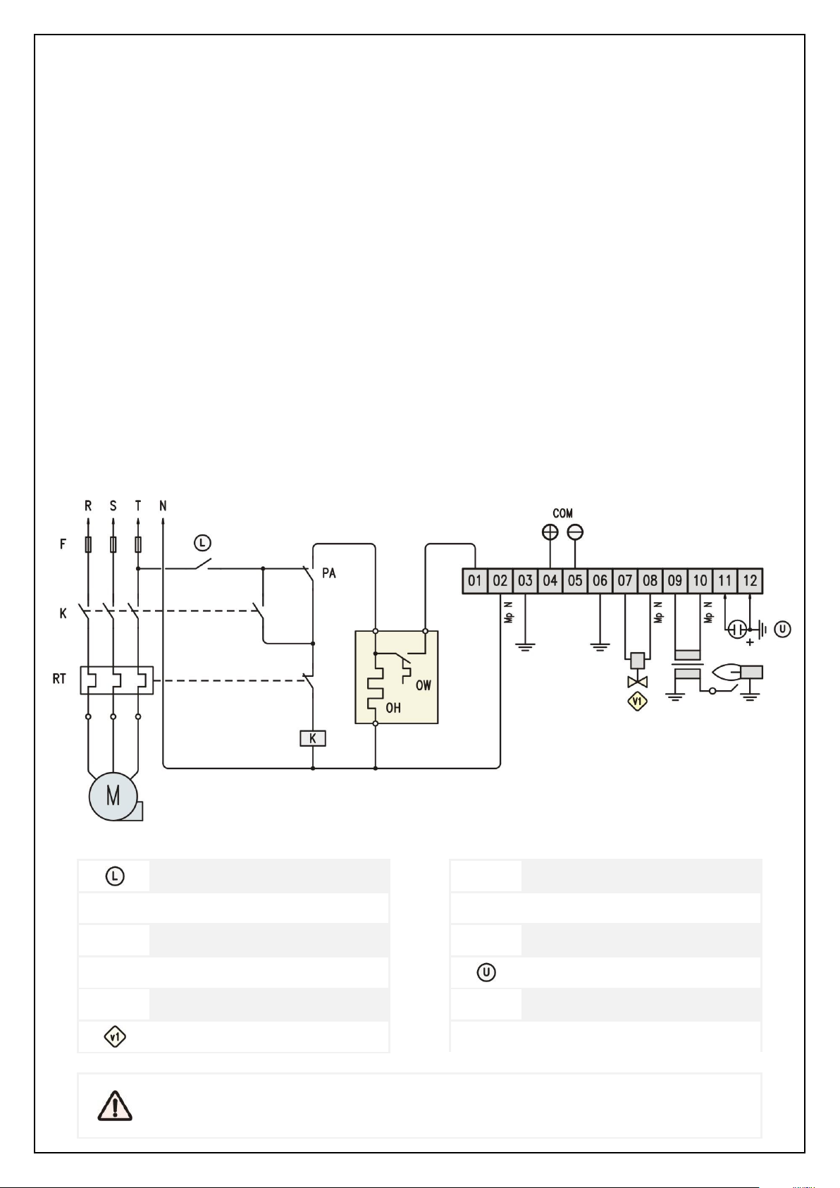
The burner control unit Quad is suitable for the
control of direct ignition burners up to 350 kW,
pursuant to EN 746-2.
Flame control by means of UV scanner or ionization
rod (even shared with ignition).
Time and cycle are configurable: the same device can
be used to control different types of gas and oil
burners, meeting all relevant requirements.
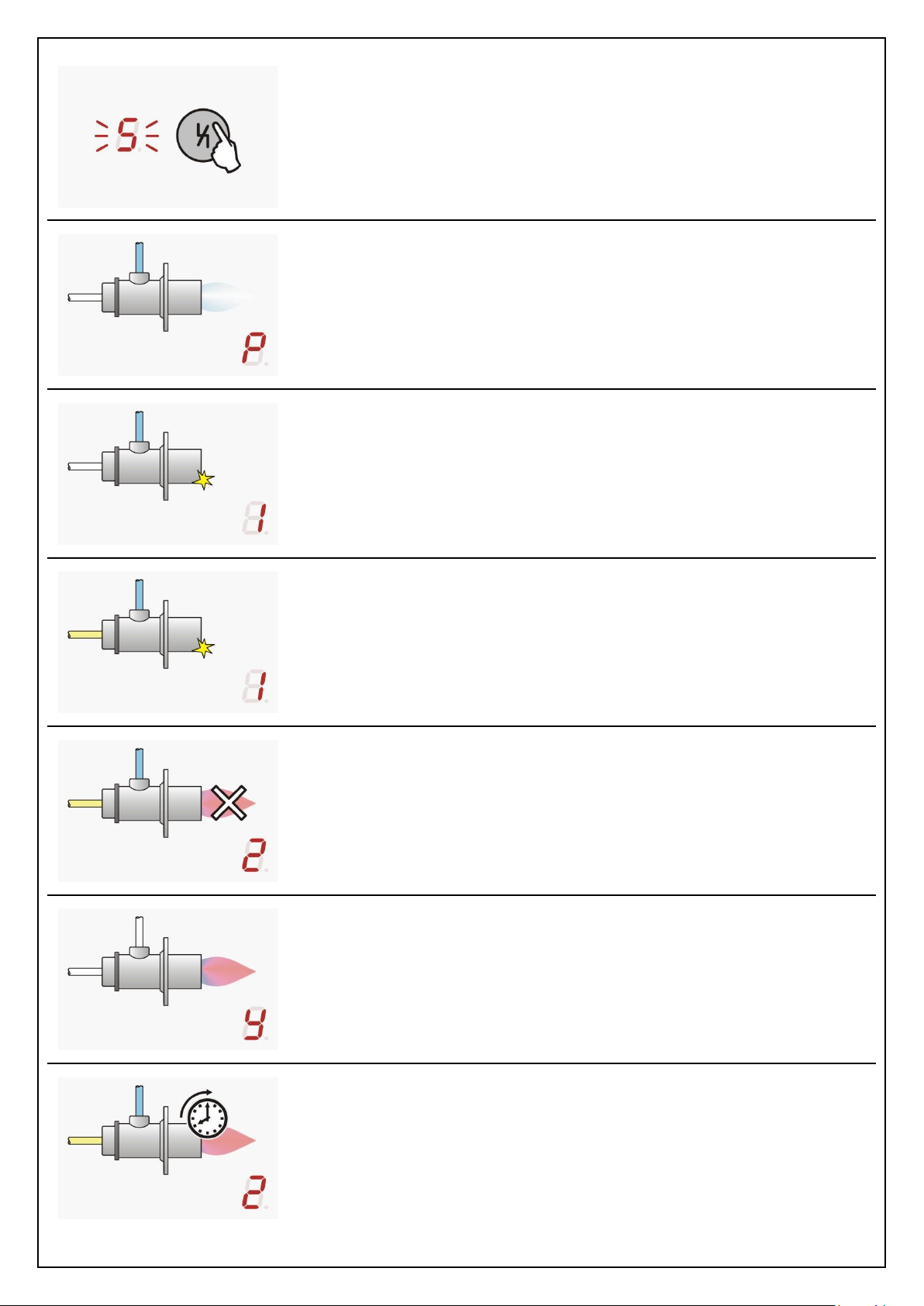
A led-bar flame signal indicator and an advanced self-
diagnostic system provides the display of either the
cycle status, lockouts and failures.
Remote control and supervision of the burner can be
implemented through traditional electrical wiring, or
through built-in communication line.
Optional TraxGateways are available for conversion of
TraxBus to standard fieldbus (like PROFIBUS-DP).
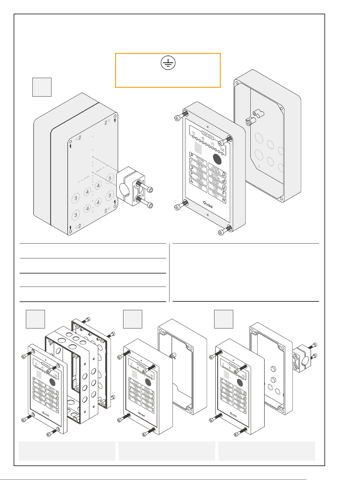
SAFETY INFORMATION
Read and understand this manual before installing, operating, or servicing this unit. This unit must be installed
according to this manual and local regulations. The drawings may show units without covers or safety shields to
illustrate details. Disconnect power supply and follow all usual safety precautions before carrying out any operation
on the device. Be sure to reinstall covers or shields before operating any devices.
The device is not user serviceable, a faulty device must be put out of order and sent back for servicing.
CONTRIVE manufactures products used as components in a wide variety of industrial systems and equipment. The
selection and application of products remain the responsibility of the equipment manufacturer or end user.
CONTRIVE accepts no responsibility for the way its products are incorporated into the final system design. All
systems or equipment designed to incorporate a product manufactured by CONTRIVE must be supplied to the end
user with appropriate warnings and instructions as to the safe use and operation of that part.
Any warnings provided by CONTRIVE must be promptly provided to the end user.
CONTRIVE guarantees for two years from the date of manufacture of its product to replace, or, at its option, to
repair any product or part thereof (except fuses and with some limitations for tubes and photocells) which is found
defective in material or workmanship or which otherwise fails to conform to the description of its sales order.
CONTRIVE makes no warranty of merchantability or any other warranty express or implied. CONTRIVE assumes no
liability for any personal injury, property damage, losses, or claims arising from misapplication of its products.
CONFORMITY
Gas Equipment Directive (90/396/EEC)
Low Voltage Equipment Directive (73/23/EEC)
Machinery Directive (89/392/EEC)
EMC Directive (89/336/EEC)
EN298 compliant
EN230 compliant
EN746-2 compliant
DVGW type certification No. CE-0085BM0346
Certified by Gosstandart pursuant to GOST-R

© 2000 CONTRIVE • B1401.EN 0211 2www.contrive.it
INTERNAL LABEL
Please perform the following tasks after receiving the product:
Inspect the unit for damage. If the product appears damaged upon receipt, contact the shipper immediately.
Verify receipt of the correct power supply voltage option by checking the label.
If you have received the wrong model or the device does not function properly, contact your supplier.
FRONT PANEL
INTERNAL
FITTING SCREWS
1
7
POWER SUPPLY FUSE
FLAME SIGNAL BARGRAPH
2
8
TERMINAL BOARD
STATUS DISPLAY
3
9
EXPANSION SOCKET
RESET / SHUTOFF BUTTON
4
DEVICE DATA
QRCODE
ORDER CODE
SERIAL NUMBER

© 2000 CONTRIVE • B1401.EN 0211 3www.contrive.it
WIRING DIAGRAM
01 POWER SUPPLY PHASE
02 POWER SUPPLY NEUTRAL
03 GROUND
04 TRAXBUS INTERFACE POSITIVE
05 TRAXBUS INTERFACE NEGATIVE
06 GROUND
07 GAS VALVE (V1)
08 POWER SUPPLY NEUTRAL
09 IGNITION TRANSFORMER OUTPUT
10 POWER SUPPLY NEUTRAL
11 FLAME DETECTOR INPUT (ROD, UV-)
12 GROUND
LEXTERNAL LIMITS
USE POWER, SIGNAL AND CONTROL CABLE SUITABLE FOR THE TYPE OF OPERATION AND COMPLYING WITH ALL REGULATIONS
DO NOT ROUTE CONNECTIONS TOGETHER WITH FREQUENCY CONVERTER CABLES OR CABLES EMITTING STRONG FIELDS
PROVIDE RELIABLE CONNECTION TO PE (PROTECTION EARTH) AND BURNER FRAME, RECOMMENDED WIRE GAUGE: 4 mm2
ALL ELECTRONIC SYSTEMS MUST BE SUPPLIED BY A DEDICATED TRANSFORMER IN A TN-S EARTHING SYSTEM
USE UNSCREENED HIGH-VOLTAGE CABLE FOR IGNITION AND IONIZATION ROD LINES, LAYING CABLES INDIVIDUALLY, AVOIDING
METAL CONDUITS. KEEP HIGH VOLTAGE IGNITION CABLES AS SHORT AS POSSIBLE, AVOIDING LOOPS AND KEEP ALL OTHER
CABLES, ESPECIALLY THOSE OF UV OR IONIZATION ROD, AS FAR APART AS POSSIBLE
POWER SUPPLY FUSE
The device and following burner loads are protected by means of an embedded POWER SUPPLY FUSE [7]:
TERMINAL 07 : GAS VALVE V1 TERMINAL 09 : IGNITION TRANSFORMER
This fuse must be replaced only with same type and value component: 3,15 A quickblow (5x20mm).
STATUS DISPLAY
The STATUS DISPLAY [3] gives, at any time, a clear indication about the working conditions of both the burner and
the equipment, making it easier to detect any failure occurring in the system or the device.
CYCLE
MANUAL SHUTDOWN
UNIT HAS BEEN PUT OUT OF SERVICE FROM
PUSH BUTTON. PUSH AGAIN TO RESTORE.
IGNITION
1ST SAFETY TIME. BURNER IGNITION TRIAL
WITH PILOT GAS OPEN.
TIMER SHUTDOWN
BURNER HAS BEEN TURNED OFF BY
OPTIONAL INTERNAL TIMER.
PILOT BURNER ON
PILOT GAS VALVE IS OPEN, BURNER ON
UNTIL SHUTDOWN, LOCKOUT OR FAILURE
REMOTE SHUTDOWN
BURNER HAS BEEN TURNED OFF BY REMOTE
CONTROL THROUGH FIELDBUS.
POSTCOMBUSTION
WAITING FOR FLAME QUENCHING AFTER
LOCKOUT OR SHUTDOWN REQUEST.
PREPURGE
PURGE OF COMBUSTION CHAMBER OR
DELAY FOR ILLEGAL FLAME PROVING.
POSTPURGE
PURGE OF COMBUSTION CHAMBER, SHOWN
TOGETHER WITH ASSOCIATED CODE.

© 2000 CONTRIVE • B1401.EN 0211 4www.contrive.it
WARNINGS
SELF-TEST
SELF DIAGNOSIS, EVERY TIME THE UNIT IS
POWERED OR THE BURNER IS STARTED.
CONFIGURATION
UNIT IN CONFIGURATION MODE THROUGH
COMMUNICATION LINK.
LIFETIME EXPIRED
MAINTENANCE REQUIRED AFTER 500.000
IGNITIONS. PUSH AGAIN TO START ANYWAY.
LOCKOUTS
STANDBY
WAITING FOR RESET WHEN PROGRAMMED
FOR STANDBY MODE AFTER POWER-ON.
FLAME LOSS
FLAME QUENCHING DURING NORMAL
BURNER OPERATION.
ILLEGAL DETECTION
PARASITE FLAME DETECTION DURING PRE-
PURGE, POSTPURGE OR POSTCOMBUSTION.
COMMUNICATION TIMEOUT
MISSING COMMANDS FROM REMOTE
SUPERVISOR.
IGNITION FAILURE
NO FLAME DETECTED AT THE END OF
IGNITION TRIAL, 1ST SAFETY TIME.
RESETABLE FAILURES
IGNITION DEVICE FAILURE
IGNITION DEVICE UNPLUGGED, DEFECTIVE OR
NOT WORKING PROPERLY.
MISSING GROUND JOINT | SOFT JUMP
POOR SPARK RETURN PATH (I.E.: BAD
GROUND CONNECTION TO BURNERS HEAD).
GAS VALVE FAILURE
GAS VALVE UNPLUGGED, DEFECTIVE OR NOT
WORKING PROPERLY.
STRONG EMI | CONFIG ERROR
ELECTRO MAGNETIC INTERFERENCE ABOVE
ADMISSIBLE LIMIT, CONFIGURATION ERROR.
OUTPUT RELAYS FAILURE
SHORT CIRCUIT ON OUTPUT RELAYS CONTACT
SAFETY RELAY WILL DISCONNECT LOADS.
TIMEBASE FAILURE
MISMATCH BETWEEN 1ST AND 2ND TIMEBASE
GENERATORS.
SUPERVISOR ILLEGAL COMMAND
SUPERVISOR SENT AN ILLEGAL COMMAND
(i.e.: RESET WHILE SYSTEM IS RUNNING).
SYSTEM WATCHDOG
MICROPROCESSOR ISN’T OPERATING
PROPERLY.
NON RESETABLE FAILURES
PUSH BUTTON FAILURE
PUSH BUTTON FOUND CLOSED AT SELF TEST.
FAILURE OR AVOID PUSHING DURING TEST.
MASTER SAFETY RELAY FAILURE
SHORT CIRCUIT ON SAFETY RELAY CONTACT.
OUTPUT RELAYS WILL DISCONNECT LOADS.
SYSTEM ERROR
PROGRAM ERRORS, CORRUPTION IN
FIRMWARE MEMORY.

© 2000 CONTRIVE • B1401.EN 0211 5www.contrive.it
GAS BURNER
When the equipment is used for gas burners, the prescriptions set forth in the European Standard EN298 (including
any further revision) must be completely fulfilled, along with the specific requirements of any National regulation in
force in the Country where the equipment is installed.
Combustion air and optional process limits are controlled by external circuitry.
A complete self test is deployed at power-on and at any reset from lockout, possible failures are reported on the
front panel display.
Depending on the configuration, the system starts the prepurge time (autostart) or waits for manual start-up
(standby mode). A flame simulation test is carried out during Prepurge.
The gas valve will be activated only if the ignition device is detected (power supply current) during preignition time.
The gas valve remains open during the programmed safety time, if a valid flame signal is detected within the safety
time the valve is kept open: the burner is on. The system will lockout if no flame is detected.
Flame quenching during burner operation will force the system to lockout, recycle or respark.
There are different options to stop the burner:
switching off the power supply;
pressing the front panel button (manual shutdown);
remote communication command (remote halt);
internal timer (if enabled).
A postcombustion time (max 20 seconds) is allowed after a lockout or shutdown request, followed by pospurge.
The device can stop the burner after programmed auto shutoff time (5m to 20h50m) of continuous operation and
restart again, providing that all the equipment and burner safety tests are successfully performed.
EXTERNAL LIMITS
PA
LOW AIR PRESSURE SWITCH
F
LINE FUSE
DUAL ROD CIRCUIT
K
BLOWER POWER RELAY
UV SENSOR
RT
BLOWER THERMAL PROTECTION
SINGLE ROD CIRCUIT
M
BLOWER MOTOR
COM
TraxBus INTERFACE
GAS VALVE
ALL SAFETY SWITCHES SHOULD BE APPROVED AS LIMIT CONTROLS
THE USE OF ELECTRONIC SWITCHES MAY CAUSE ERRATIC OPERATIONS

© 2000 CONTRIVE • B1401.EN 0211 6www.contrive.it
OIL BURNER
When the equipment is used for oil burners, the prescriptions set forth in the European Standard EN230 (including
any further revision must be completely fulfilled, along with the specific requirements of any National regulation in
force in the Country where the equipment is installed.
Combustion air and optional process limits are controlled by external circuitry.
A complete self test is deployed at power-on and at any reset from lockout, possible failures are reported on the
front panel display.
Depending on the configuration, the system starts the prepurge time (autostart) or waits for manual start-up
(standby mode). A flame simulation test is carried out during Prepurge.
Ignition device is activated during Prepurge time for oil burners (long preignition).
The fuel valve will be activated only if the ignition device is detected (power supply current) during preignition time.
The fuel valve remains open during the programmed safety time, if a valid flame signal is detected within the safety
time the valve is kept open: the burner is on. The system will lockout if no flame is detected.
Flame quenching during burner operation will force the system to lockout, recycle or respark.
There are different options to stop the burner:
switching off the power supply;
pressing the front panel button (manual shutdown);
remote communication command (remote halt);
internal timer (if enabled).
A postcombustion time (max 20 seconds) is allowed after a lockout or shutdown request, followed by pospurge.
The device can stop the burner after programmed auto shutoff time (5m to 20h50m) of continuous operation and
restart again, providing that all the equipment and burner safety tests are successfully performed.
EXTERNAL LIMITS
OH
OIL HEATHER
F
LINE FUSE
OW
OIL THERMOSTAT
K
BLOWER POWER RELAY
PA
LOW AIR PRESSURE SWITCH
RT
BLOWER THERMAL PROTECTION
UV SENSOR
M
BLOWER / PUMP MOTOR
COM
TraxBus INTERFACE
FUEL VALVE
QUAD USES UV SCANNER FOR OIL, INCREASING SAFETY AND RELIABILITY
IGNITION DEVICE MUST BE SUITABLE FOR LONG PREIGNITION TIMES

© 2000 CONTRIVE • B1401.EN 0211 7www.contrive.it
PARAMETERS
BEHAVIOUR AT POWER ON –LOCKOUT
Q101 START-UP MODE AUTOSTART A
STANDBY S
BEHAVIOUR DURING PREPURGE
Q305 PREPURGE TIME 1” … 001
DEFAULT 1”… 250” 250
BEHAVIOUR DURING IGNITION
Q401 PRE-IGNITION TIME 0,5”
Q402 STARTUP SAFETY TIME 2” … 02
DEFAULT 3”… 25” 25
BEHAVIOUR DURING OPERATION
Q507 OPERATING SAFETY TIME 1” … 01
DEFAULT 1”… 12” 12
Q508 ALLOWED POSTCOMBUSTION TIME < 20”
Q509 AUTO-SHUTOFF TIME 00:05 … 01
20:50 … FA
Q510 AUTO-SHUTOFF MODE OFF –
MANUAL M
AUTOMATIC A
Q512 FLAME LOSS LOCKOUT L
RECYCLE C
RESPARK K
BEHAVIOUR DURING POSTPURGE
Q602 POSTPURGE TIME 1” … 001
DEFAULT 1” … 250” 250
COMMUNICATION SETTINGS
Q701 ZONE (SEGMENT) 00 …
… ZZ
Q702 UNIT (NODE) 00 …
… ZZ
Q703 BAUD RATE 4800
9600
19200
38400
Q704 TIMEOUT OFF
00’ 04”…
… 16’ 40”
LOCKOUT DUE TO COMMUNICATION TIMEOUT CAN OCCUR DURING
NORMAL CYCLE, WHEN COMMUNICATION TIMEOUT IS ENABLED
GENERAL SETTINGS
Q801 BURNER TYPE GAS G
OIL O
F809 DEVICE NOTES
F810 DEVICE PASSWORD
HARDWARE
Q001 POWER SUPPLY VOLTAGE 230 Vac 230
115 Vac 115
Q002 ENCLOSURE LIGHT ALUMINIUM N
STANDARD ALUMINIUM A
LOW PROFILE ALUMINIUM B
POLYCARBONATE P
CONFIGURATION
The device is configurable using the free software tool
QPro thru the communication line (terminals 4 and 5, by
means of TraxInterface3 or TraxGateway) or from the
expansion socket (by means of specific adapter).
The unit must be in manual shutdown to enter confi-
guration environment: display shows an horizontal dash
while linked. Some parameters are password protected.
and can be modified by authorized users or by factory.

© 2000 CONTRIVE • B1401.EN 0211 8www.contrive.it
Q101 –START-UP MODE
At power-on, once the self-test has been successfully completed, the unit waits in
STANDBY mode until a reset operation is performed from local push button or
through a fieldbus remote command. Setting AUTOSTART mode, the cycle starts
automatically, unless the units has been turned off while in lockout.
Q305 –PREPURGE TIME
Set prepurge time in forced draught burners according to EN 676 requirements.
Any air valve and/or butterfly valve controlled by external process must be kept
open during the whole prepurge time.
During this time an illegal flame test is carried out.
Q401 –PRE-IGNITION TIME
The ignition transformer is turned on 500 ms before the gas valve to check the
correct operation before to open the gas.
This is a fixed time and cannot be changed.
Q402 –STARTUP SAFETY TIME
Set the correct time following EN 746-2 (or other relevant) requirements:
Natural draught burners ≤ 70 kW → 10” > 70 kW → 5”
IGNITION POWER ≤33% NOMINAL POWER WITH MAXIMUM OF 350 KW
Forced draught burners ≤ 350 kW → 5” >350kW→3”
IGNITION POWER ≤ 10% NOMINAL POWER WITH MAXIMUM OF 350 KW
Q507 –OPERATING SAFETY TIME
If the flame fails during operation, gas valve is switched off within this safety time
that must be in accordance with relevant application standards (default for EN 298
is 1” and must not exceed 3” including valves closing time for EN 746-2).
F508 –ALLOWED POST-COMBUSTION TIME
The flame signal is allowed for 20” once gas valve has been closed.
Lockout occurs if the flame is detected after the post-combustion time.
Q509 –AUTO SHUT-OFF TIME
An automatic shutoff is performed after the specified time since burner on.

© 2000 CONTRIVE • B1401.EN 0211 9www.contrive.it
Q510 –AUTO SHUT-OFF MODE
Behavior after an automatic shut-off. In AUTOMATIC mode a complete burner
restart cycle is deployed, performing the test of the whole system, as per Standard
requirements, within 24 hours of continuous operation.
In MANUAL mode the burner waits for reset.
Q512 –FLAME LOSS
Determines the behavior at flame loss during normal burner operation.
For burners with occasionally unstable flame signal a single recycle (including
prepurge) or direct respark can be attempted. The setting is to be determined on
the basis of burner capacity and relevant application standard.
Q602 –POSTPURGE TIME
Follow EN 676 requirements to set correct postpurge time in forced draught
burners. Any air valve and/or butterfly valve controlled by external process must
be kept open during the whole postpurge time.
During this time an illegal flame test is carried out.
Q701 –ZONE (SEGMENT)
Communication identifier: group or zone belonging the burner control.
All alphanumeric (uppercase/lowercase) characters are valid identifiers.
Q702 –UNIT (NODE)
Communication identifier: burner control unit within a given area, group or zone.
All alphanumeric (uppercase/lowercase) characters are valid identifiers.
Q703 –BAUD RATE
Communication baud rate: 4800, 9600, 19200, 38400.
Q704 –COMMUNICATION TIMEOUT
Communication timeout up to 1000 seconds (4” step). Set 0 to disable.
Q801 –BURNER TYPE
Selecting OIL type burner the ignition device will be activated also during the
prepurge to allow the detection of oil leakage that will be ignited, leading to an
illegal flame detection. Application and settings must be made in accordance to
EN 230 (or other relevant standard) requirements.
Q001 –POWER SUPPLY VOLTAGE
Power supply must be wired at terminal 01 and 02, for burner control unit and
loads (gas valve and ignition transformer), both protected by the embedded fuse.
Optional safety interlock limits could be wired on the main supply phase.

© 2000 CONTRIVE • B1401.EN 0211 10 www.contrive.it
Q002 –ENCLOSURE
Quad is available in 4 different enclosure options. Standard version is N, all other types are available on request.
According to European Standard EN60529 a minimum protection degree IP40 must be guaranteed, raised to IP54 for
open air application.
1 EXTERNAL FITTING HOLES (4) 106 x 186 mm
4.2 mm SELF TAPPING OR M5 THREAD FORMING SCREW
2 BREAKABLE FITTING HOLES (4) 77 x 182 mm
4,0 mm DIAMETER
3 BREAKABLE HOLES FOR WIRING (4) Ø 19,0 mm
SUITABLE FOR PG11 CABLE GLAND
4 BREAKABLE HOLES FOR WIRING (4) Ø 15,5 mm
SUITABLE FOR PG9 CABLE GLANDS
CAST ALLUMINIUM ALLOY EN AB 46100 IP65
OVERALL DIMENSION: 200 x 120 x 71 mm WEIGHT: 1130 g
ELECTROSTATIC POLYESTER POWDER COATING COLOR: GRAY
OPTIONAL FITTING CLAMPS FOR PIPES
VERTICAL MOUNTING OUTSIDE DIAMETER 6 … 76 mm
HORIZONTAL MOUNTING OUTSIDE DIAMETER 6 … 63 mm
N
ALUMINIUM ENCLOSURES MUST BE
CONNECTED TO PROTECTIVE EARTH
P
A
B
CAST ALUMINIUM ALLOY
200 x 120 x 92 mm | 1510 g
CAST ALUMINIUM ALLOY
200 x 120 x 71 mm | 1300 g
POLYCARBONATE UL-V0
200 x 120 x 96 mm | 750 g

© 2000 CONTRIVE • B1401.EN 0211 11 www.contrive.it
FIELDBUS REMOTE CONTROL
TraxBus using busbars or single wire lines
Ref. to TraxInterface3literature [B1300] for wiring details
Complete remote control and supervision is possible
through built-in serial communication interface using
proprietary fieldbus, designed for reliable operation in
harsh industrial environments with simplified wiring.
Communication protocol could be easily implemented
into any programmable controller for great efficiency
and low cost. Ready to use gateways are available to
convert TraxBus into standard industry fieldbus systems.
Typical communication time at different baud rates are
summarized below.
Since any supervisor takes some time for internal
processing, the real performance of the fieldbus must be
computed adding such delay.
POLLING TIME FOR 1 BURNER
4800 9600 19200 38400
COMMAND 15 ms 8 ms 4 ms 2 ms
ANSWER 15 ms 8 ms 4 ms 2 ms
OVERALL 30 ms 16 ms 8 ms 4 ms
POLLING TIME FOR 10 BURNERS
4800 9600 19200 38400
COMMAND 150 ms 80 ms 40 ms 20 ms
ANSWER 150ms 80 ms 40 ms 20 ms
OVERALL 300 ms 160 ms 80 ms 40 ms
POLLING TIME FOR 100 BURNERS
4800 9600 19200 38400
COMMAND 1,5 s 800 ms 400 ms 200 ms
ANSWER 1,5 s 800 ms 400 ms 200 ms
OVERALL 3,0 s 1600 ms 800 ms 400 ms
Messages to/from remote host supervisor must be ASCII
characters, 8 bits, no parity, 1 or 2 stop bits.
COMMAND FROM SUPERVISOR TO PERIPHERALS
Commands are issued to peripherals within a single
string terminated with Carriage Return.
< S N C KK <Cr> < Preamble (from master)
S Segment, Zone identifier
N Node, Unit identifier
C Command
KK Checksum
<Cr> Carriage return
STATUS FROM PERIPHERALS TO SUPERVISOR
Peripherals will acknowledge all valid command received
from supervisor:
> S N T KK <Cr> > Preamble (to master)
S Segment, Zone identifier
N Node, Unit identifier
T Status
KK Checksum
<Cr> Carriage return
S and N can be any alphanumeric character and must match the settings of the peripheral to be addressed.
Since Quad+Flair valid settings are within the range 01…FD, the maximum addressable units on a single bus are 252.
The special character * (star) can be used like wild card to send broadcast command: a star character instead of S will
address all existing nodes, a star character instead of N will address the whole segment, two star characters will
address all the connected units. Of course no acknowledge answer will be sent back after broadcast commands.

© 2000 CONTRIVE • B1401.EN 0211 12 www.contrive.it
CHECKSUM CALCULATION
Each command must include a valid checksum KK to be
executed, all the answers will include a valid checksum
KK that can be optionally evaluated by supervisor.
KK is the ASCII figure of the sum of all characters HEX
values, including Carriage Return. See example and use
only last two characters, ignoring trailing ones (if any).
< 0 8 S 04 <Cr> < Equals HEX 3C +
0 Equals HEX 30 +
1 Equals HEX 38 +
S Equals HEX 53 +
<Cr> Equals HEX 0D =
ASCII 104
COMMAND LIST
HBURNER HALT Q SHUTDOWN THE BURNER
RBURNER RUN Q RESTART THE BURNER FROM SHUTDOWN
BUNLOCK Q RESET THE BURNER FROM LOCKOUT, MUST BE CONFIRMED §1
YUNLOCK CONFIRM Q CONFIRM THE RESET FROM LOCKOUT
EEXTEND Q FORCE THE BURNER TO PREPURGE UNTIL A ‘COMPLETE’ COMMAND IS RECEIVED §2
CCOMPLETE Q COMPLETE THE PREPURGE TIME
SSTATUS Q NO ACTION BUT STATUS REQUEST
§1 THE SUPERVISOR MUST SEND A RESET CONFIRMATION WITHIN 25 SECONDS FROM PERIPHERAL ACKNOWLEDGE TO RESET COMMAND.
AN UNCONFIRMED RESET COMMAND WILL BE CANCELLED AFTER 25 SECONDS. RECEIVING AN ILLEGAL RESET COMMAND (i.e.: RESET
WHILE NOT IN LOCKOUT) A LOCKOUT WILL BE FORCED TO PREVENT DANGEROUS OPERATION.
§2 RECEIVING AN EXTEND COMMAND THE BURNER IS FORCED TO PREPURGE, IF THE BURNER IS RUNNING IT WILL BE TURNED OFF
PERFORMING A COMPLETE RECYCLE INCLUDING SELF TEST. WHEN A ‘COMPLETE’COMMAND IS RECEIVED, THE REMAINING PREPURGE
TIME (IF ANY) WILL BE COMPLETED PROCEEDING TO NEXT CYCLE STEP.
STATUS LIST
SSTOP Q BURNER LOCKOUT OR FAILURE
0MANUAL SHUTDOWN Q BURNER OUT OF SERVICE, SHUTDOWN FROM LOCAL PUSH BUTTON
HHALT Q BURNER SHUTDOWN
PPREPURGE Q PREPURGE IN PROGRESS
1IGNITION Q BURNER IGNITION TRIAL IN PROGRESS
2BURNER ON Q BURNER ON
gLIFE EXPIRED Q POST-LOCKOUT MAINTENANCE ALERT
YPOSTCOMBUSTION Q WAITING FOR FLAME QUENCHING
WPOSTPURGE Q POSTPURGE IN PROGRESS

© 2000 CONTRIVE • B1401.EN 0211 13 www.contrive.it
A SELF TEST IS PERFORMED IN LESS THAN 1”,
ONCE SUCCESSFULLY COMPLETED THE BURNER
IS READY TO START.
IF THE UNIT HAS BEEN TURNED OFF WHILE IN
LOCKOUT OR PARAMETER Q101 HAS BEEN SET
TO STANDBY,IT WILL BE NECESSARY TO RESET
THE UNIT BY MEANS OF LOCAL PUSH BUTTON,
OR FIELDBUS COMMAND.
A FLAME SIMULATION CHECK IS CONDUCTED
DURING WAITING OR PREPURGE TIME.
AFTER THE PRESET WAITING OR PREPURGE
TIME HAS ELAPSED, THE IGNITION DEVICE IS
ACTIVATED AND VERIFIED, THEN THE PILOT
VALVE IS OPEN.
PILOT PROVING PERIOD STARTS IF THE FLAME
IS DETECTED WITHIN THE SAFETY TIME.
IF NO FLAME IS DETECTED DURING THE SAFETY
TIME A FAULT LOCKOUT OCCURS.
FLAME FAILURES DURING OPERATION LEADS
TO LOCKOUT RESTART OR RECYCLE DEPENDING
ON Q512 PARAMETER SETTING.
A SHUTDOWN REQUEST FROM FIELDBUS
COMMAND OR LOCAL PUSH BUTTON TURNS
OFF THE BURNER, WAITING FOR ALLOWED
POSTCOMBUSTION AND POSTPURGE TIME.
AN AUTOMATIC SHUTOFF OF THE BURNER CAN
BE ACTIVATED, AFTER A PRESET TIME OF
BURNER RUNNING. THE BURNER CAN WAIT
FOR A MANUAL RESET OR RESTART IN
AUTOMATIC MODE. A SELF TEST IS MADE AT
EVERY RESTART.
THIS PARAMETER MAY BE SET IN THIS WAY
ONLY IF THE BURNER CAN RESTART AS
INTENDED IN ALL OPERATING PHASES.
PROGRAM SEQUENCE

© 2000 CONTRIVE • B1401.EN 0211 14 www.contrive.it
TECHNICAL DATA
POWER SUPPLY
VOLTAGE 115 or 230 V +10-15%
FREQUENCY 50/60 Hz §1
LINE FUSE 3,15 A QUICKBLOW - 5x20mm
POWER CONSUMPTION 3 VA MAX
POWER DISSIPATION 2 W MAX
LIFECYCLE COUNTER 524288 IGNITIONS
§1 SINEWAVE, QUASI-SINEWAVE, SQUAREWAVE
FLAME DETECTION
MINIMUM IONIZATION CURRENT > 1 A
CURRENT LIMITATION 1 mA
SIGNAL DISPLAY 0…100 A
DETECTOR LINE LENGTH < 30 m
SINGLE ROD LINE LENGTH < 1 m
DETECTOR VOLTAGE 250 Vac
DETECTOR INSULATION > 50 M
ENVIRONMENT
OPERATING TEMPERATURE 0…60 °C
STORAGE TEMPERATURE -20…80 °C
PROTECTION CLASS (EN 69529) IP65
RELATIVE HUMIDITY 90% MAX
MOUNTING POSITION ANY
OUTPUTS
RATED VOLTAGE 250 Vac MAX
SWITCHING VOLTAGE 277 Vac MAX
LOAD CURRENT 3 A MAX
MINIMUM CURRENT 1 mA @ 5 V
BREAKING CAPACITY 750 VA MAX
COMMUNICATION INTERFACE
VOLTAGE 30 Vdc MAX
FIELDBUS TraxBus
BAUD RATE 4800, 9600, 19200, 38400
C O N F I G U R A T I O N
Q002
Q001
Q 8 0 1
Q 1 0 1
Q 3 0 5
Q 4 0 2
Q 5 0 7
Q 6 0 2
Q 5 1 2
Q 5 1 0
Q U A D
N
230
G
A
020
03
01
001
L
-
DEFAULT
DEVICE CLASSIFICATION ACCORDING TO EN298
A / B
M / B
L / C / R
L
B
N (B)
DEVICE CLASSIFICATION ACCORDING TO EN230
A / B
I / T / M
L / C / R
L
B
N (B)
CONTRIVE S.r.l. I-24040 SUISIO (Bergamo) via Enrico Fermi 18
ANY ILLUSTRATIONS, PHOTOGRAPHS, OR EXAMPLES USED IN THIS MANUAL ARE PROVIDED AS EXAMPLES ONLY AND MAY NOT APPLY TO ALL PRODUCTS TO
WHICH THIS MANUAL IS APPLICABLE. THE PRODUCTS AND SPECIFICATIONS DESCRIBED IN THIS MANUAL OR THE CONTENT AND PRESENTATION OF THE
MANUAL MAY BE CHANGED WITHOUT NOTICE TO IMPROVE THE PRODUCT AND/OR THE MANUAL.
PRODUCT NAMES, CORPORATE NAMES, OR TITLES USED WITHIN THIS DOCUMENT MAY BE TRADEMARKS OR REGISTERED TRADEMARKS OF OTHER COMPANIES,
AND ARE MENTIONED ONLY IN AN EXPLANATORY MANNER TO THE READERS’ BENEFIT, AND WITHOUT INTENTION TO INFRINGE.
WHILE EVERY EFFORT HAS BEEN MADE TO MAKE SURE THE INFORMATION IN THIS DOCUMENT IS CORRECT, CONTRIVE CAN NOT BE LIABLE FOR ANY DAMAGES
WHATSOEVER FOR LOSS RELATING TO THIS DOCUMENT.
© COPYRIGHT 2009 CONTRIVE SRL ITALY. ALL RIGHT RESERVED.
Table of contents
Other Contrive Control Unit manuals
Popular Control Unit manuals by other brands

Emerson
Emerson Numatics DeviceLogix G2-2 Series Quick start manual

Burkert
Burkert 6014 operating instructions

Coreline
Coreline 150 Installation, operation & maintenance manual

ADTRAN
ADTRAN T200 H2TU-R manual

Nederman
Nederman TAV 100 user manual

UTC Fire and Security
UTC Fire and Security interlogix VT4010 Installation & operation instructions