manuals.online logo
Brands
  1. Home
  2. •
  3. Brands
  4. •
  5. Ublox
  6. •
  7. Control Unit
  8. •
  9. Ublox ZOE-M8 Series Quick setup guide

Ublox ZOE-M8 Series Quick setup guide

ZOE-M8 series
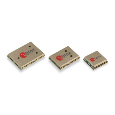
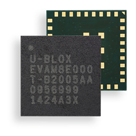
Ultra-small u-blox M8 SiP modules
Hardware integration manual
Abstract
This document describes the hardware features and specifications of the u-blox ZOE-M8G and
ZOE-M8Q GNSS SiP (system in package) modules.
www.u-blox.com
UBX-16030136 - R09
ZOE-M8 series - Hardware integration manual
UBX-16030136 - R09 Page 2 of 34
Production information Document information
Document information
Title
ZOE-M8 series
Subtitle
Ultra-small u-blox M8 SiP modules
Document type
Hardware integration manual
Document number
UBX-16030136
Revision and date
R09
4-May-2020
Document status
Production information
Product status
Corresponding content status
In Development /
Prototype
Objective Specification
Target values. Revised and supplementary data will be published later.
Engineering Sample
Advance Information
Data based on early testing. Revised and supplementary data will be published later.
Initial Production
Early Production Information
Data from product verification. Revised and supplementary data may be published later.
Mass Production /
End of Life
Production Information
Document contains the final product specification.
European Union regulatory compliance
ZOE-M8G and ZOE-M8Q SiPs comply with all relevant requirements for RED 2014/53/EU. The ZOE-M8G/Q Declaration of
Conformity (DoC) is available at www.u-blox.com under Support > Product resources > Conformity Declaration.
This document applies to the following products:
Product name
Type number
ROM/FLASH version
PCN reference
ZOE-M8G
ZOE-M8G-0-10
ROM SPG 3.01 / Flash FW SPG 3.01
N/A
ZOE-M8Q
ZOE-M8Q-0-10
ROM SPG 3.01 / Flash FW SPG 3.01
N/A
u-blox or third parties may hold intellectual property rights in the products, names, logos and designs included in this
document. Copying, reproduction, modification or disclosure to third parties of this document or any part thereof is only
permitted with the express written permission of u-blox.
The information contained herein is provided “as is” and u-blox assumes no liability for its use. No warranty, either express or
implied, is given, including but not limited to, with respect to the accuracy, correctness, reliability and fitness for a particular
purpose of the information. This document may be revised by u-blox at any time without notice. For the most recent
documents, visit www.u-blox.com.
Copyright © u-blox AG.
ZOE-M8 series - Hardware integration manual
UBX-16030136 - R09 Page 3 of 34
Production information Contents
Contents
Document information................................................................................................................................2
Contents ..........................................................................................................................................................3
1Hardware description...........................................................................................................................5
1.1 Overview........................................................................................................................................................ 5
2Design-in...................................................................................................................................................6
2.1 Power management ...................................................................................................................................6
2.1.1 Main supply voltage (VCC)................................................................................................................ 6
2.1.2 V_CORE (only on ZOE-M8Q).............................................................................................................6
2.1.3 DC/DC converter (only on ZOE-M8Q) ............................................................................................. 6
2.1.4 Backup power supply (V_BCKP)....................................................................................................... 7
2.2 Interfaces......................................................................................................................................................8
2.2.1 UART interface....................................................................................................................................8
2.2.2 Display data channel (DDC) interface.............................................................................................8
2.2.3 SPI interface ........................................................................................................................................9
2.2.4 SQI interface ........................................................................................................................................9
2.3 I/O pins.........................................................................................................................................................10
2.3.1 Time pulse ..........................................................................................................................................10
2.3.2 External interrupt .............................................................................................................................10
2.3.3 External LNA enable.........................................................................................................................10
2.3.4 Electromagnetic interference and I/O lines.................................................................................10
2.4 Real-time clock (RTC)...............................................................................................................................11
2.4.1 RTC using a crystal...........................................................................................................................11
2.4.2 RTC using an external clock ...........................................................................................................11
2.4.3 Time aiding.........................................................................................................................................11
2.5 RF input.......................................................................................................................................................12
2.5.1 Passive antenna................................................................................................................................12
2.5.2 Improved jamming immunity .........................................................................................................13
2.5.3 Active antenna ..................................................................................................................................13
2.6 Safe boot mode (SAFEBOOT_N)............................................................................................................14
2.7 System reset (RESET_N) ........................................................................................................................14
2.8 Pin description ...........................................................................................................................................14
2.9 Typical schematic .....................................................................................................................................17
2.10 Design-in checklist....................................................................................................................................18
2.10.1 General considerations....................................................................................................................18
2.10.2 Schematic design-in for ZOE-M8 GNSS SiPs.............................................................................18
2.11 Layout design-in checklist ......................................................................................................................19
2.12 Layout..........................................................................................................................................................19
2.12.1 Footprint.............................................................................................................................................20
2.12.2 Paste mask ........................................................................................................................................20
2.12.3 Placement ..........................................................................................................................................20
ZOE-M8 series - Hardware integration manual
UBX-16030136 - R09 Page 4 of 34
Production information Contents
2.13 Layout design-in: Thermal management.............................................................................................20
2.14 EOS/ESD/EMI precautions......................................................................................................................21
2.14.1 Electrostatic discharge (ESD)........................................................................................................21
2.14.2 ESD protection measures ...............................................................................................................21
2.14.3 Electrical overstress (EOS) .............................................................................................................21
2.14.4 EOS protection measures...............................................................................................................22
2.14.5 Electromagnetic interference (EMI) .............................................................................................22
2.14.6 Applications with cellular modules ...............................................................................................23
3Product handling and soldering ..................................................................................................... 25
3.1 Packaging, shipping, storage and moisture preconditioning ..........................................................25
3.2 ESD handling precautions.......................................................................................................................25
3.3 Safety precautions ...................................................................................................................................25
3.4 Soldering .....................................................................................................................................................26
3.4.1 Soldering paste .................................................................................................................................26
3.4.2 Reflow soldering................................................................................................................................26
3.4.3 Optical inspection.............................................................................................................................26
3.4.4 Repeated reflow soldering ..............................................................................................................26
3.4.5 Wave soldering ..................................................................................................................................26
3.4.6 Rework ................................................................................................................................................26
3.4.7 Use of ultrasonic processes ...........................................................................................................26
4Product testing ................................................................................................................................... 27
4.1 Test parameters for the OEM manufacturer......................................................................................27
4.2 System sensitivity test............................................................................................................................27
4.2.1 Guidelines for sensitivity tests ......................................................................................................27
4.2.2 ‘Go/No go’ tests for integrated devices........................................................................................27
Appendix ....................................................................................................................................................... 28
AComponent selection ........................................................................................................................ 28
A.1 External RTC (Y1)......................................................................................................................................28
A.2 RF band-pass filter (F1)...........................................................................................................................28
A.3 Optional SQI flash (U3).............................................................................................................................29
A.4 Inductor for the DC/DC converter (L1)..................................................................................................29
A.5 External LNA (U1) .....................................................................................................................................30
A.6 RF ESD protection diode..........................................................................................................................30
A.7 Ferrite beads (FB1) ...................................................................................................................................30
A.8 Feed-through capacitors.........................................................................................................................30
A.9 Standard capacitors.................................................................................................................................30
BGlossary ................................................................................................................................................. 31
Related documents ................................................................................................................................... 32
Revision history.......................................................................................................................................... 33
Contact.......................................................................................................................................................... 34
ZOE-M8 series - Hardware integration manual
UBX-16030136 - R09 Hardware description Page 5 of 34
Production information
1Hardware description
1.1 Overview
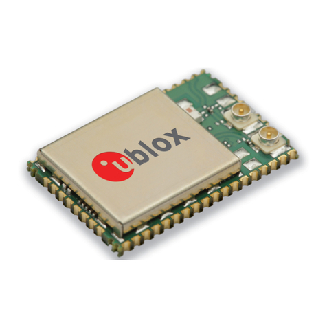
u-blox ZOE-M8 standard precision GNSS SiP (system in package) modules feature the high
performance u-blox M8 GNSS engine. ZOE-M8’s ultra-miniature form factor integrates a complete
GNSS receiver including SAW filter, LNA and TCXO.
The ZOE-M8 SiPs are targeted for applications that require a small size without compromising the
performance. For RF optimization, the ZOE-M8 SiPs integrate a front-end SAW filter and an
additional front-end LNA for increased jamming immunity and easier antenna integration. A passive
antenna can be used to provide a highly integrated system solution with a minimal eBOM.
The ZOE-M8 SiPs can be easily integrated in manufacturing thanks to the advanced S-LGA (soldered
land grid array) packaging technology, which enables easier and more reliable soldering processes
compared to a normal LGA (land grid Array) package.
☞For product features, see the ZOE-M8 Data sheet [1].
☞To determine which u-blox product best meets your needs, see the product selector tables on the
u-blox website www.u-blox.com.
ZOE-M8 series - Hardware integration manual
UBX-16030136 - R09 Design-in Page 6 of 34
Production information
2Design-in
To obtain good performance with ZOE-M8 GNSS receiver SiPs, there are a number of issues requiring
careful attention during the design-in. These include:
Power supply: Good performance requires a clean and stable power supply.
Interfaces: Ensure correct wiring, rate and message setup on the SiP and your host system.
Antenna interface: For optimal performance, seek short routing, matched impedance and no
stubs.
2.1 Power management
The ZOE-M8G is a 1.8 V variant, while the ZOE-M8Q is a 3.0 V variant and has an option to make use
of the built-in DC/DC converter to reduce the power consumption.
The ZOE-M8 GNSS SiPs provide two supply pins: VCC and V_BCKP. They can be supplied
independently or tied together, depending on the intended application.
Additionally, ZOE-M8Q has the option to make use of a built-in DC/DC converter and thus comes with
two additional supply pins, V_CORE and V_DCDC_OUT. The supply voltages are explained in the
following subsections.
2.1.1 Main supply voltage (VCC)
During operation, the ZOE-M8 GNSS SiPs are supplied through the VCC pin. Built-in LDOs generate
stabilized voltages for the core and RF domains of the chip, respectively. The current at VCC depends
heavily on the current state of the system and is in general very dynamic.
☞Do not add any series resistance (< 0.1 Ω) to the VCC supply, as it will generate input voltage noise
due to the dynamic current conditions.
The digital I/Os of the ZOE-M8 GNSS SiPs are also referred and supplied to the VCC voltage.
2.1.2 V_CORE (only on ZOE-M8Q)
V_CORE draws the main current of the ZOE-M8Q. The current at V_CORE depends heavily on the
current system state and in general exhibits very dynamic behavior. It can be supplied either by main
supply or with the built-in DC/DC converter, see section 2.1.3.
☞Do not add any series resistance greater than 0.1 Ωto the V_CORE supply as it will generate input
voltage noise due to the dynamic current conditions.
☞If a DC/DC converter is not used, supply V_CORE with the same supply as used for the VCC.
2.1.3 DC/DC converter (only on ZOE-M8Q)
ZOE-M8Q comes with a built-in DC/DC converter to supply V_CORE, thus enabling significant power
savings. For more information, see the ZOE-M8 Data sheet [1]. It requires an external inductor (L1)
and capacitor (C1). For the recommended inductor and capacitor, see Appendix A.4 and Appendix A.9.
ZOE-M8 series - Hardware integration manual
UBX-16030136 - R09 Design-in Page 7 of 34
Production information
Figure 1 : Circuit for DC/DC converter with ZOE-M8Q
The DC/DC converter block provides an energy conversion efficiency of up to 85%. The actual value
depends on the current drawn and which external inductor (L1) and capacitor (C1) are used.
To enable the DC/DC converter there are two options.
Option 1: In production, send a one-time command to the ZOE-M8Q, which enables the DC/DC
converter permanently in ZOE-M8Q’s internal OTP memory. The command to be sent is “B5 62 06 41
0C 00 00 00 03 1F C5 90 E1 9F FF FF FE FF 45 79” and it will be acknowledged (UBX-ACK). After doing
a reset, it can be verified by checking the UBX-MON-LLC message.
☞Ensure a stable VCC supply when sending the command to enable the DC/DC converter.
Option 2: Alternatively, if no SQI flash is used, the DC/DC converter can be enabled by defining the SQI
flash pins as shown in Table 1.
Pin #
Name
State
Remarks
D1
SQI_D0
Open
Must be left open!
C1
SQI_D1
GND
Must be connected to GND!
E3
SQI_D2
GND
Must be connected to GND!
F3
SQI_D3
Open
Must be left open!
E1
SQI_CLK
GND
Must be connected to GND!
D3
SQI_CS_N
GND
Must be connected to GND!
Table 1: Enable DC/DC converter
☞If the SQI flash pins are used to enable the DC/DC converter, ensure that the SQI flash pins are set
exactly as mentioned in Table 1, otherwise it can cause malfunction of the ZOE-M8Q.
2.1.4 Backup power supply (V_BCKP)
In the case of a power failure at main supply VCC, the backup domain and optional RTC oscillator are
supplied by V_BCKP. Providing a V_BCKP supply maintains the time (RTC) and the GNSS orbit data
in the backup RAM. This ensures that any subsequent re-starts after a VCC power failure will benefit
from the stored data, providing a faster TTFF.
The GNSS satellite ephemeris data is typically valid for up to 4 hours. To enable hot starts, ensure
that the battery or capacitor at V_BCKP is able to supply the backup current for at least 4 hours. For
warm starts or when using the AssistNow Autonomous, the V_BCKP source must be able to supply
current for up to a few days.
☞If no backup supply is available, V_BCKP can be connected to the reserved neighbor pin G9.
☞Avoid high resistance on the V_BCKP line: during the switch from main supply to backup supply, a
short current adjustment peak can cause high voltage drop on the pin with possible malfunctions.
☞For description of the different power operating modes, see the ZOE-M8 Data sheet
[1].
ZOE-M8 series - Hardware integration manual
UBX-16030136 - R09 Design-in Page 8 of 34
Production information
2.2 Interfaces
The ZOE-M8 GNSS SiPs provide UART, SPI and DDC (I2C-compatible) interfaces for communication
with a host CPU. Additionally, an SQI interface is available for connecting the ZOE-M8 GNSS SiPs with
an optional external flash memory.
The UART, SPI and DDC pins are supplied by VCC and operate at this voltage level.
Four dedicated pins can be configured as either 1 x UART and 1 x DDC or a single SPI interface
selectable by the D_SEL pin. Table 2 below provides the port mapping details.
Pin #
Pin D4 (D_SEL) = “high” (left open)
Pin D4 (D_SEL) = “Low” (connected to GND)
J5
UART TXD
SPI MISO
J4
UART RXD
SPI MOSI
B1
DDC SCL
SPI CLK
A2
DDC SDA
SPI CS_N
Table 2: Communication interfaces overview
☞It is not possible to use the SPI interface simultaneously with the DDC or UART interface.
☞For debugging purposes, it is recommended to have a second interface, for example, DDC available
that is independent from the application and accessible via test-points.
For each interface, define a dedicated pin to indicate that data is ready to be transmitted. The TXD
Ready signal indicates that the receiver has data to transmit. Each TXD Ready signal is associated
with a particular interface and cannot be shared. A listener can wait on the TXD Ready signal instead
of polling the DDC or SPI interfaces. The UBX-CFG-PRT message lets you configure the polarity and
the number of bytes in the buffer before the TXD Ready signal goes active. The TX Ready signal can
be mapped, for example, to UART TX. The TXD Ready function is disabled by default.
☞The TXD Ready functionality can be enabled and configured by using suitable AT commands sent
to the u-blox cellular module in question that supports the feature. For more information, see the
GPS Implementation and Aiding Features in u-blox wireless modules [5].
☞The TXD Ready feature is supported on several u-blox cellular module products.
2.2.1 UART interface
A UART interface is available for serial communication to a host CPU. The UART interface supports
configurable data rates with the default at 9600 baud. Signal levels are related to the VCC supply
voltage. An interface based on RS232 standard levels (+/- 7 V) can be realized using level shifter ICs
such as the Maxim MAX3232.
Hardware handshake signals and synchronous operation are not supported.
A signal change on the UART RXD pin can also be used to wake up the receiver in power save mode
(see the u-blox 8 / u-blox M8 Receiver Description including Protocol Specification
[2]).
☞Designs must allow access to the UART and the SAFEBOOT_N pin for future service, updates, and
reconfiguration.
2.2.2 Display data channel (DDC) interface
An I2C-compatible display data channel (DDC) interface is available for serial communication with a
host CPU.
ZOE-M8 series - Hardware integration manual
UBX-16030136 - R09 Design-in Page 9 of 34
Production information
☞The SCL and SDA pins have internal pull-up resistors sufficient for most applications. However,
depending on the speed of the host and the load on the DDC lines additional external pull-up
resistors might be necessary. For the speed and clock frequency, see the ZOE-M8 Data sheet [1].
☞To make use of DDC interface, the D_SEL pin must be left open.
☞The ZOE-M8 GNSS SiPs DDC interface provides serial communication with u-blox cellular
modules. See the specification of the applicable cellular module to confirm compatibility.
2.2.3 SPI interface
Use the SPI interface to provide a serial communication with a host CPU. If the SPI interface is used,
UART and DDC are deactivated, because they share the same pins.
☞To make use of the SPI interface, the D_SEL pin must be connected to GND.
2.2.4 SQI interface
An external SQI (Serial Quad Interface) flash memory can be connected to the ZOE-M8 GNSS SiPs.
The SQI interface provides the following options:
Store the current configuration permanently
Save data logging results
Hold AssistNow Offline and AssistNow Autonomous data
☞In addition, the ZOE-M8 GNSS SiPs can make use of a dedicated flash firmware with an external
SQI flash memory. The flash memory with these SiPs can be used to run firmware out of flash and
to update the firmware as well. Running the firmware from the SQI flash requires a minimum SQI
flash size of 8 Mbit.
☞If the flash is not used to run the firmware, it has to be programmed with the FIS-only option.
☞The voltage level of the SQI interface follows the VCC level. Therefore, the SQI flash must be
supplied with the same voltage as VCC of the ZOE-M8 SiPs. It is recommended to place a
decoupling capacitor (C4) close to the supply pin of the SQI flash.
☞Make sure that the SQI flash supply range matches the voltage supplied at VCC.
Figure 2: Connecting an external SQI flash memory
An SQI flash size of 8 Mbit is sufficient to save AssistNow Offline and AssistNow Autonomous
information as well as current configuration data. However, for ZOE-M8 SiPs to run firmware from the
SQI flash and provide space for logging results, a minimum size of 8 Mbit may not be sufficient
depending on the amount of data to be logged.
ZOE-M8 series - Hardware integration manual
UBX-16030136 - R09 Design-in Page 10 of 34
Production information
☞For more information about supported SQI flash devices, see section A.3.
☞Make sure that the SAFEBOOT_N pin is available for entering safe boot mode. Programming the
SQI flash memory with a flash firmware is done typically at production. For this purpose, the ZOE-
M8 GNSS SiPs must enter the safe boot mode. For more information about SAFEBOOT_N pin, see
section 2.6.
2.3 I/O pins
All I/O pins make use of internal pull-ups to VCC. Thus, there is no need to connect unused pins to
VCC.
2.3.1 Time pulse
A configurable time pulse signal is available with the ZOE-M8 GNSS SiPs.
The TIMEPULSE output generates pulse trains synchronized with GPS or UTC time grid with intervals
configurable over a wide frequency range. Thus, it may be used as a low frequency time
synchronization pulse or as a high frequency reference signal.
By default, the time pulse signal is configured to 1 pulse per second. For more information, see the u-
blox 8 / u-blox M8 Receiver Description including Protocol Specification [2].
2.3.2 External interrupt
EXTINT is an external interrupt pin with fixed input voltage thresholds with respect to VCC (see the
ZOE-M8 Data sheet
[1] for more information). It can be used for wake-up functions in power save
mode on all u-blox M8 SiPs and modules and for aiding, leave open if unused. By default, the external
interrupt is disabled.
If the EXTINT is not used for an external interrupt function, it can be used for some other purpose, for
example, as an output pin for the TXD Ready feature to indicate that the receiver has data to transmit.
For further information, see the u-blox 8 / u-blox M8 Receiver Description Including Protocol
Specification [2].
☞If the EXTINT is configured for on/off switching of the ZOE-M8 GNSS SiPs, the internal pull-up
becomes disabled. Therefore ensure that the EXTINT input is always driven within the defined
voltage level by the host.
2.3.3 External LNA enable
LNA_EN pin can be used to turn on and off an external LNA. The external LNA will be turned off in
power save mode in on/off operation in OFF stage, or in software backup mode the external LNA will
also be turned off.
2.3.4 Electromagnetic interference and I/O lines
Any I/O signal line (length > ~3 mm) can act as an antenna and may pick up arbitrary RF signals
transferring them as noise into the GNSS receiver. This specifically applies to unshielded lines, lines
where the corresponding GND layer is remote or missing entirely, and lines close to the edges of the
printed circuit board. If for example, a cellular signal radiates into an unshielded high-impedance line,
it is possible to generate noise in the order of volts and not only distort receiver operation but also
damage it permanently.
On the other hand, noise generated at the I/O pins will emit from unshielded I/O lines. Receiver
performance may be degraded when this noise is coupled into the GNSS antenna (see Figure 17).
ZOE-M8 series - Hardware integration manual
UBX-16030136 - R09 Design-in Page 11 of 34
Production information
In case of improper shielding, it is recommended to use resistors or ferrite beads (see Appendix A.7)
on the I/O lines in series. Choose these components with care because they also affect the signal rise
times. Alternatively, feed-through capacitors with good GND connection close to the GNSS receiver
can be used (see Appendix A.8).
EMI protection measures are particularly useful when RF emitting devices are placed next to the
GNSS receiver and/or to minimize the risk of EMI degradation due to self-jamming. An adequate
layout with a robust grounding concept is essential in order to protect against EMI. For more
information, see section 2.14.6.3.
2.4 Real-time clock (RTC)
The use of the RTC is optional to maintain time in the event of power failure at VCC. It requires
V_BCKP to be supplied in case of power failure at VCC. The RTC is required for hot start, warm start,
AssistNow Autonomous, AssistNow Offline and in some power save mode operations.
The time information can either be generated by connecting an external RTC crystal to the SiP, by
connecting an external 32.768 kHz signal to the RTC input, or by time aiding of the GNSS receiver at
every start-up.
If a power save mode is used, an external RTC crystal must be connected. Optionally an external
32.768 kHz signal can be provided.
2.4.1 RTC using a crystal
The easiest way to provide time information to the receiver is to connect an RTC crystal to the
corresponding pins of the RTC oscillator, RTC_I and RTC_O. There is no need to add load capacitors
to the crystal for frequency tuning because they are already integrated in the chip. Using an RTC
crystal provides the lowest current consumption to V_BCKP in case of a power failure. On the other
hand, it increases the BOM costs and requires space for the RTC crystal.
Figure 3: RTC crystal
2.4.2 RTC using an external clock
Some applications can provide a suitable 32.768 kHz external reference to drive the SiP RTC. The
external reference can simply be connected to the RTC_I pin. Make sure that the 32.768 kHz reference
signal is always turned on and the voltage at the RTC_I pin does not exceed 350 mVpp. Adjustment
of the voltage level (typically 200 mVpp) can be achieved with a resistive voltage divider followed by a
DC blocking capacitor in the range of 1 nF to 10 nF. Also make sure that the frequency versus
temperature behavior of the external clock is within the recommended crystal specifications shown
in section A.1.
2.4.3 Time aiding
Time can also be sent by UBX message at every start-up of the ZOE-M8 GNSS SiPs. This can be done
to enable warm starts, AssistNow Autonomous and AssistNow Offline. This can be done when no RTC
is maintained.
To enable hot starts correctly, the time information must be known accurately and thus the
TimeMark feature must be used.
ZOE-M8 series - Hardware integration manual
UBX-16030136 - R09 Design-in Page 12 of 34
Production information
For more information about time aiding or TimeMark, see the u-blox 8 / u-blox M8 Receiver Description
including Protocol Specification
[2].
☞For information on this use case, it is mandatory to contact u-blox support team.
☞For power save mode operations where the RTC is needed, the time aiding cannot be used. This is
because the host does not have any information about when the ZOE-M8 GNSS SiPs turns from
OFF status to ON status during an ON/OFF operation of power save mode.
2.5 RF input
The ZOE-M8 GNSS SiPs RF-input is already matched to 50 Ohms and has an internal DC block. The
ZOE-M8 SiPs are optimized to work with a passive antenna.
The ZOE-M8 GNSS SiPs can receive and track multiple GNSS systems (for example, GPS, Galileo,
GLONASS, BeiDou and QZSS signals). Because of the dual-frequency RF front-end architecture, two
GNSS signals (from GPS L1C/A, GLONASS L1OF, Galileo E1B/C and BeiDou B1) can be received and
processed concurrently. This concurrent operation is extended to 3-GNSS systems whenever GPS
and Galileo are used in addition to GLONASS or BeiDou.
2.5.1 Passive antenna
ZOE-M8 SiPs are optimized to work with passive antennas. The internal SAW filter inside followed by
an LNA is a good compromise for most applications from jamming and performance point of view.
Figure 4: Typical circuit with passive antennas
Where best performance needs to be achieved and no jamming sources are present, an LNA (U1) can
be placed close to the antenna.
Figure 5: Circuit for best performance
The LNA (U1) can be selected to deliver the performance needed by the application in terms of:
Noise figure (sensitivity)
Selectivity and linearity (robustness against jamming)
Robustness against RF power and ESD
ZOE-M8 series - Hardware integration manual
UBX-16030136 - R09 Design-in Page 13 of 34
Production information
☞The external LNA (U1) must be placed close to the passive antenna to achieve the best
performance.
If power save mode is used and the minimum current consumption has to be achieved, the external
LNA should also be turned off. The LNA_EN pin can be used to turn off the external LNA.
ESD discharge into the RF input cannot always be avoided during assembly and / or field use with this
approach! To provide additional robustness, an ESD protection diode, as listed in Appendix A.6, can
be placed in front of the LNA to GND.
☞If the VCC supply is also used to supply the external LNA, make sure some good filtering is in place
for the external LNA supply because of the noise on the VCC. This means that a series ferrite bead
FB1 and a decoupling capacitor to GND must be used (see section A.7).
2.5.2 Improved jamming immunity
If strong out-band jammers are close to the GNSS antenna (for example, a GSM antenna), GNSS
performance can be degraded or the maximum input power of the ZOE-M8 GNSS SiPs RF input can
be exceeded. In that case, the SAW filter (F1) must be put in front of the external LNA (U1).
It should be noted that the insertion loss of the SAW filter (F1) directly affects the system noise figure
and hence the system performance.
Figure 6: Circuit for improved jamming immunity
2.5.3 Active antenna
In case an active antenna is used, the active antenna supply circuit must be added just in front of the
SiPs RF-input.
Figure 7: Active antenna supply circuit
ZOE-M8 series - Hardware integration manual
UBX-16030136 - R09 Design-in Page 14 of 34
Production information
2.6 Safe boot mode (SAFEBOOT_N)
If the SAFEBOOT_N pin is “low” at startup, the ZOE-M8 GNSS SiPs start in safe boot mode and does
not begin GNSS operation. In safe boot mode, the SiP runs from an internal LC oscillator and starts
regardless of any configuration provided by the configuration pins. Thus, it can be used to recover
from situations where the SQI flash has become corrupted.
For communication by UART in safe boot mode, a training sequence (0x 55 55 at 9600 baud) can be
sent by the host to the ZOE-M8 GNSS SiPs in order to enable communication. After sending the
training sequence, the host must wait for at least 2 ms before sending messages to the receiver. For
further information, see the u-blox 8 / u-blox M8 Receiver Description including Protocol Specification
[2].
Safe boot mode is used in production to program the SQI flash. It is recommended to have the
possibility to pull the SAFEBOOT_N pin “low” when the SiP starts up. This can be provided using an
externally connected test point or via a host CPUs digital I/O port.
2.7 System reset (RESET_N)
The ZOE-M8 GNSS SiPs provide a RESET_N pin to reset the system. The RESET_N is input-only with
internal pull-up resistor. It must be at low level for at least 10 ms to make sure RESET_N is detected.
Leave RESET_N open for normal operation. The RESET_N complies with the VCC level and can be
actively driven high.
☞Use RESET_N in critical situations only to recover the system. The real-time clock (RTC) will also
be reset and thus immediately afterwards the receiver cannot perform a hot start.
☞In reset state, the SiP consumes a significant amount of current. It is therefore recommended to
use RESET_N only as a reset signal and not as an enable/disable.
2.8 Pin description
Pin #
SiP
Name
I/O
Description
Remark
A1
All
GND
Ground
Ensure good GND connection
A2
All
SDA / SPI CS_N
I/O
Serial interface.
See section 2.2
A3
All
GND
Ground
Ensure good GND connection
A4
All
RF_IN
I
GNSS signal input
See section 2.5
A5
All
GND
Ground
Ensure good GND connection
A6
All
Reserved
I/O
Reserved. Do not connect.
Must be left open!
A7
All
GND
Ground
Ensure good GND connection
A8
All
GND
Ground
Ensure good GND connection
A9
All
GND
Ground
Ensure good GND connection
B1
All
SCL / SPI CLK
I
Serial interface.
See section 2.2
B9
All
GND
Ground
Ensure good GND connection
C1
All
SQI_D1
I
Data line 1 to external SQI flash memory
or DC/DC configuration pin.
Leave open if not used.
C3
All
TIMEPLUSE
O
Time pulse output
Leave open if not used.
C4
All
SAFEBOOT_N
I
Used for programming the SQI flash
memory and testing purposes.
Leave open if not used.
C5
All
LNA_EN
O
LNA on/off signal connected to internal
LNA
Leave open if not used.
C6
All
PIO15
I/O
Digital I/O
Leave open if not used.
C7
All
GND
Ground
Ensure good GND connection
ZOE-M8 series - Hardware integration manual
UBX-16030136 - R09 Design-in Page 15 of 34
Production information
C9
All
GND
Ground
Ensure good GND connection
D1
All
SQI_D0
I/O
Data line 0 to external SQI flash memory
or DC/DC configuration pin.
Leave open if not used.
D3
All
SQI_CS_N
I/O
Chip select for external SQI flash memory
or DC/DC enable pin.
Leave open if not used.
D4
All
D_SEL
I
Interface selector
See section 2.2
D6
All
GND
Ground
Ensure good GND connection
D9
All
GND
Ground
Ensure good GND connection
E1
All
SQI_CLK
I/O
Clock for external SQI flash memory or
DC/DC configuration pin.
Leave open if not used.
E3
All
SQI_D2
I/O
Data line 2 to external SQI flash memory
or DC/DC configuration pin.
Leave open if not used.
E7
All
GND
Ground
Ensure good GND connection
E9
All
Reserved
I/O
Reserved
Do not connect. Must be left open!
F1
All
Reserved
I/O
Reserved
Do not connect. Must be left open!
F3
All
SQI_D3
I/O
Data line 3 to external SQI flash memory
or DC/DC configuration pin.
Leave open if not used.
F4
All
Reserved
I/O
Reserved
Do not connect. Must be left open!
F6
All
PIO14
I/O
Digital I/O
Leave open if not used.
F7
All
GND
Ground
Ensure good GND connection
F9
All
Reserved
I/O
Reserved
Do not connect. Must be left open!
G1
ZOE-M8G
VCC
I
Supply voltage
Clean and stable supply needed
ZOE-M8Q
V_CORE
I
Core supply voltage
Connect to VCC if DCDC not used
G3
All
GND
Ground
Ensure good GND connection
G4
All
PIO13 / EXTINT
I
External interrupt
Leave open if not used.
G5
All
Reserved
I/O
Reserved
Do not connect. Must be left open!
G6
All
GND
Ground
Ensure good GND connection
G7
All
GND
Ground
Ensure good GND connection
G9
All
Reserved
I/O
Reserved
Do not connect. Must be left open!
Only exception is V_BCKP, which can
be connected to this pin if not used.
H1
ZOE-M8G
VCC
I
Supply voltage
Clean and stable supply needed
ZOE-M8Q
V_DCDC_OUT
O
DC/DC converter output
Connect to VCC if DCDC not used
H9
All
V_BCKP
I
Backup supply
J1
All
VCC
I
Supply voltage
Clean and stable supply needed
J2
All
VCC
I
Supply voltage
Clean and stable supply needed
J3
All
GND
Ground
Ensure good GND connection
J4
All
RXD/SPI MOSI
I
Serial interface
See section 2.2.
J5
All
TXD/SPI MISO
O
Serial interface
See section 2.2.
J6
All
RESET_N
I
System reset
See section 2.7.
J7
All
RTC_I
I
RTC input
Connect to GND if no RTC Crystal
attached.
J8
All
RTC_O
O
RTC output
Leave open if no RTC crystal
attached.
J9
All
GND
Ground
Ensure good GND connection
Table 3: Pinout
ZOE-M8 series - Hardware integration manual
UBX-16030136 - R09 Design-in Page 16 of 34
Production information
Figure 8: ZOE-M8G pin assignment
Figure 9: ZOE-M8Q pin assignment
☞For more information about the pin assignments, see the ZOE-M8 Data sheet
[1].
ZOE-M8 series - Hardware integration manual
UBX-16030136 - R09 Design-in Page 17 of 34
Production information
2.9 Typical schematic
Figure 10: Typical schematic for the ZOE-M8G
Figure 11: Typical schematic for the ZOE-M8Q using a DC/DC converter
ZOE-M8 series - Hardware integration manual
UBX-16030136 - R09 Design-in Page 18 of 34
Production information
Figure 12: Typical schematic for the ZOE-M8Q without a DC/DC converter
2.10 Design-in checklist
2.10.1 General considerations
Check power supply requirements and schematic:
Is the power supply voltage within the specified range? See how to connect power in section 2.1
and section 2.9.
Compare the peak current consumption of ZOE-M8 GNSS SiPs with the specification of your
power supply.
GNSS receivers require a stable power supply. Avoid series resistance in your power supply line
(the line to VCC) to minimize the voltage ripple on VCC.
Backup battery
For achieving a minimal time-to-first-fix (TTFF) after a power down (warm starts, hot starts),
make sure to connect a backup battery to V_BCKP, and use an RTC. If not used, make sure
V_BCKP is connected to neighbor pin G9.
Antenna/ RF input
Make sure the antenna is not placed close to noisy parts of the circuitry and is not facing noisy
parts (such as micro-controller, display).
Make sure your RF front end is chosen according your design, see section 2.5.
☞For more information on dealing with interference issues, see the GPS Antenna Application Note
[3].
2.10.2 Schematic design-in for ZOE-M8 GNSS SiPs
For a minimal design with the ZOE-M8 GNSS SiPs, the following functions and pins need to be
considered:
Connect the power supply to VCC and V_BCKP.
If you use DC/DC converter on the ZOE-M8Q, ensure the external inductor and capacitor are in
place in between V_DCDC_OUT and V_CORE.
ZOE-M8 series - Hardware integration manual
UBX-16030136 - R09 Design-in Page 19 of 34
Production information
Ensure an optimal ground connection to all ground pins of the ZOE-M8 GNSS SiPs.
Choose the required serial communication interfaces (UART, SPI or DDC) and connect the
appropriate pins to your application.
If you need hot or warm start in your application, connect a backup battery to V_BCKP and add an
RTC circuit.
2.11 Layout design-in checklist
Follow this checklist for the layout design to get an optimal GNSS performance.
Layout optimizations (see section 2.12)
Is the ZOE-M8 GNSS SiP placed according to the recommendation in section 2.12.3?
Is the grounding concept optimal?
Are all the GND pins well connected with GND?
Is the 50 Ohm line from the antenna to the SiP (micro strip / coplanar waveguide) as short as
possible?
Assure low serial resistance in VCC power supply line (choose a line width > 400 µm).
Assure all VCC pins are well connected with the power supply line.
Keep the power supply line as short as possible.
If DC/DC is used on the ZOE-M8Q, ensure the inductor and capacitor are connected close to the
ZOE-M8Q V_CORE and V_DCDC_OUT pins and the capacitor has a good GND connection.
Design a GND guard ring around the optional RTC crystal lines and GND below the RTC circuit.
Add a ground plane underneath the GNSS SiP to reduce interference. This is especially important
for the RF input line.
For improved shielding, add as many vias as possible around the micro strip/coplanar waveguide,
around the serial communication lines, underneath the GNSS SiP, and so on.
Calculation of the micro strip for RF input
The micro strip / coplanar waveguide must be 50 Ohms and routed in a section of the PCB where
minimal interference from noise sources can be expected. Make sure around the RF line is only
GND, as well as under the RF line.
In case of a multi-layer PCB, use the thickness of the dielectric between the signal and the 1st
GND layer (typically the 2nd layer) for the micro strip / coplanar waveguide calculation.
If the distance between the micro strip and the adjacent GND area (on the same layer) does not
exceed 5 times the track width of the micro strip, use the “Coplanar Waveguide” model in AppCad
to calculate the micro strip and not the “micro strip” model.
2.12 Layout
This section provides important information for designing a reliable and sensitive GNSS system.
GNSS signals at the surface of the earth are about 15 dB below the thermal noise floor. Signal loss at
the antenna and the RF connection must be minimized as much as possible. When defining a GNSS
receiver layout, the placement of the antenna with respect to the receiver, as well as grounding,
shielding and jamming from other digital devices are crucial issues and need to be considered very
carefully.
ZOE-M8 series - Hardware integration manual
UBX-16030136 - R09 Design-in Page 20 of 34
Production information
2.12.1 Footprint
Figure 13: Recommended footprint (bottom view)
Symbol
Typical [mm]
e
0.50
g
0.25
f
0.25
D1
4.50
E1
4.50
P
0.27 diameter
Table 4: Footprint dimensions
2.12.2 Paste mask
The paste mask shall be same as the copper pads with a paste thickness of 80 µm.
☞These are recommendations only and not specifications. The exact geometry, distances, stencil
thicknesses and solder paste volumes must be adapted to the customer’s specific production
processes (for example, soldering).
2.12.3 Placement
A very important factor in achieving maximum GNSS performance is the placement of the receiver on
the PCB. The connection to the antenna must be as short as possible to avoid jamming into the very
sensitive RF section.
Make sure that RF-critical circuits are clearly separated from any other digital circuits on the system
board. To achieve this, position the receiver digital part towards your digital section of the system
PCB.
2.13 Layout design-in: Thermal management
During design-in do not place the module near sources of heating or cooling. The receiver oscillator is
sensitive to sudden changes in ambient temperature which can adversely impact satellite signal
tracking.
Sources can include co-located power devices, cooling fans or thermal conduction via the
PCB.
Take into account the following questions when designing in the module.
Is the receiver placed away from heat sources?
Is the receiver placed away from air-cooling sources?
Is the receiver shielded by a cover/case to prevent the effects of air currents and rapid
environmental temperature changes?

This manual suits for next models

4

Other Ublox Control Unit manuals

Ublox TOBY-L1 series Quick setup guide

Ublox

Ublox TOBY-L1 series Quick setup guide

Ublox NORA-W10 Series Quick setup guide

Ublox

Ublox NORA-W10 Series Quick setup guide

Ublox NEO-M8N Quick setup guide

Ublox

Ublox NEO-M8N Quick setup guide

Ublox NINA-B1 Series User manual

Ublox

Ublox NINA-B1 Series User manual

Ublox LEXI-R422 Quick setup guide

Ublox

Ublox LEXI-R422 Quick setup guide

Ublox SARA-R42 User manual

Ublox

Ublox SARA-R42 User manual

Ublox MAX-7C-0 User manual

Ublox

Ublox MAX-7C-0 User manual

Ublox VERA-P171 User manual

Ublox

Ublox VERA-P171 User manual

Ublox C027-U20 User manual

Ublox

Ublox C027-U20 User manual

Ublox NEO-8Q Series Quick setup guide

Ublox

Ublox NEO-8Q Series Quick setup guide

Ublox SARA-R5 Series Quick setup guide

Ublox

Ublox SARA-R5 Series Quick setup guide

Ublox EVK-W262U User manual

Ublox

Ublox EVK-W262U User manual

Ublox TIM-5H Quick setup guide

Ublox

Ublox TIM-5H Quick setup guide

Ublox MPCI-L2 series Quick setup guide

Ublox

Ublox MPCI-L2 series Quick setup guide

Ublox SAM-M8Q Use and care manual

Ublox

Ublox SAM-M8Q Use and care manual

Ublox ODIN-W260 Quick setup guide

Ublox

Ublox ODIN-W260 Quick setup guide

Ublox NINA-B222-04B Quick setup guide

Ublox

Ublox NINA-B222-04B Quick setup guide

Ublox NINA-B1 Series Quick setup guide

Ublox

Ublox NINA-B1 Series Quick setup guide

Ublox EVK-NORA-B1 User manual

Ublox

Ublox EVK-NORA-B1 User manual

Ublox ZED-F9H Use and care manual

Ublox

Ublox ZED-F9H Use and care manual

Ublox TOBY-L2 series Quick setup guide

Ublox

Ublox TOBY-L2 series Quick setup guide

Ublox NORA-W36 Series Quick setup guide

Ublox

Ublox NORA-W36 Series Quick setup guide

Ublox NINA-B50 Series Quick setup guide

Ublox

Ublox NINA-B50 Series Quick setup guide

Ublox MIA-M10Q Use and care manual

Ublox

Ublox MIA-M10Q Use and care manual

Popular Control Unit manuals by other brands

Miele Con@ctivity 2.0-Stick installation instructions

Miele

Miele Con@ctivity 2.0-Stick installation instructions

Pepperl+Fuchs VAA-2E-KE1-S Original instructions

Pepperl+Fuchs

Pepperl+Fuchs VAA-2E-KE1-S Original instructions

Kobelt 2544 Owner's Operation, Installation & Maintenance Manual

Kobelt

Kobelt 2544 Owner's Operation, Installation & Maintenance Manual

Monacor ATT-212H/WS instructions

Monacor

Monacor ATT-212H/WS instructions

Honeywell REDLINK ERM5220R Product data

Honeywell

Honeywell REDLINK ERM5220R Product data

Satel INT-AV manual

Satel

Satel INT-AV manual

Enerpac VM33VAC instruction sheet

Enerpac

Enerpac VM33VAC instruction sheet

Leadshine DM542 user manual

Leadshine

Leadshine DM542 user manual

Roger Technology H70/200AC Instruction and warnings for the installer

Roger Technology

Roger Technology H70/200AC Instruction and warnings for the installer

Pickering 40-290-021 user manual

Pickering

Pickering 40-290-021 user manual

Jflow controls DM4800 SERIES Installation and maintenance manual

Jflow controls

Jflow controls DM4800 SERIES Installation and maintenance manual

NTI ENVIROMUX-RKS Wiring instruction

NTI

NTI ENVIROMUX-RKS Wiring instruction

Texas Instruments TPS5430 user guide

Texas Instruments

Texas Instruments TPS5430 user guide

Numerik Jena SCM-1000 user manual

Numerik Jena

Numerik Jena SCM-1000 user manual

Mitsubishi Electric MELSEC iQ-R-RD75P4 user manual

Mitsubishi Electric

Mitsubishi Electric MELSEC iQ-R-RD75P4 user manual

Dixon Bayco 2182 Maintenance & Operating Instructions

Dixon Bayco

Dixon Bayco 2182 Maintenance & Operating Instructions

Yoshitake DP-200 Series manual

Yoshitake

Yoshitake DP-200 Series manual

Cervis Wireless Smart HH 10 Series manual

Cervis

Cervis Wireless Smart HH 10 Series manual

manuals.online logo
manuals.online logoBrands
  • About & Mission
  • Contact us
  • Privacy Policy
  • Terms and Conditions

Copyright 2025 Manuals.Online. All Rights Reserved.