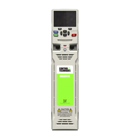
Control Techniques SM-Universal Encoder Plus User manual

EF
www.controltechniques.com
User Guide
SM-Universal
Encoder Plus
Solutions module for
Unidrive SP
Part Number: 0471-0005-06
Issue Number: 6
Version: 04.xx.xx

General Information
The manufacturer accepts no liability for any consequences resulting from
inappropriate, negligent or incorrect installation or adjustment of the optional
operating parameters of the equipment or from mismatching the variable speed
drive with the motor.
The contents of this guide are believed to be correct at the time of printing. In the
interests of a commitment to a policy of continuous development and improvement,
the manufacturer reserves the right to change the specification of the product or its
performance, or the contents of this guide, without notice.
All rights reserved. No parts of this guide may be reproduced or transmitted in any
form or by any means, electrical or mechanical including photocopying, recording or
by an information storage or retrieval system, without permission in writing from the
publisher.
Drive software version
The SM-Universal Encoder Plus can only be used with drive software version
00.11.00 onwards.
Some features of the SM-Universal Encoder Plus may not be available if the drive
software is not the latest version (01.07.00)
Option module software version
The issue 4 SM-Universal Encoder Plus option module must only be programmed
with software versions 04.xx.xx.
Failure to comply with this will result in module failure.
Copyright © May 2005 Control Techniques Drives Ltd
Issue Code: 6

SM-Universal Encoder Plus User Guide 3
Issue Number: 6 www.controltechniques.com
Contents
1 How to use this guide ................................................... 5
1.1 Intended personnel .................................................................................5
1.2 Information ..............................................................................................5
2 Safety Information ......................................................... 6
2.1 Warnings, Cautions and Notes ...............................................................6
2.2 Electrical safety - general warning ..........................................................6
2.3 System design and safety of personnel ..................................................6
2.4 Environmental limits ................................................................................7
2.5 Compliance with regulations ...................................................................7
2.6 Motor .......................................................................................................7
2.7 Adjusting parameters ..............................................................................7
3 Introduction .................................................................... 8
3.1 Features ..................................................................................................8
3.2 Solutions Module identification ................................................................8
3.3 Set-up parameters ..................................................................................9
3.4 Compatible with encoder types ...............................................................9
4 Encoder feedback selection ....................................... 18
4.1 Encoder selection ..................................................................................18
4.2 Considerations ......................................................................................20
4.3 Drive resolution / Feedback accuracy ...................................................22
5 Installing the SM-Universal Encoder Plus ................. 24
5.1 Solutions Module slots ..........................................................................24
5.2 Installation .............................................................................................24
5.3 Terminal descriptions ............................................................................26
5.4 Power supply .........................................................................................28
5.5 Encoder shield connections ..................................................................28
5.6 Grounding hardware .............................................................................29
6 Getting Started ............................................................. 37
6.1 Installation .............................................................................................37
6.2 Termination resistors .............................................................................44
6.3 Simulated encoder outputs ...................................................................45
6.4 Marker inputs ........................................................................................51
6.5 Marker outputs ......................................................................................51
6.6 Freeze inputs ........................................................................................52
6.7 Thermistor input ....................................................................................55
7 Encoder feedback positional information ................. 56
7.1 Encoder feedback positional information ..............................................56
8 Advanced Operation ................................................... 58
8.1 Serial communications ..........................................................................58
8.2 Electronic nameplate transfers ..............................................................66

4SM-Universal Encoder Plus User Guide
www.controltechniques.com Issue Number: 6
9 Parameters ...................................................................70
9.1 Introduction ............................................................................................70
9.2 Single line descriptions ..........................................................................71
9.3 Parameter descriptions ..........................................................................76
10 Diagnostics ..................................................................98
10.1 Display ...................................................................................................98
10.2 Displaying the trip history ......................................................................99
10.3 Fault finding .........................................................................................103
11 Terminal Data .............................................................104
11.1 Encoder inputs SK2 .............................................................................104
11.2 Simulated encoder outputs SK2 ..........................................................105
11.3 Drive encoder power supply ................................................................106
11.4 Encoder inputs PL1 .............................................................................107
11.5 Encoder outputs PL1 ...........................................................................107

SM-Universal Encoder Plus User Guide 5
Issue Number: 6 www.controltechniques.com
1 How to use this guide
1.1 Intended personnel
This guide is intended for personnel who have the necessary training and experience in
system design, installation, commissioning and maintenance.
1.2 Information
This guide contains information covering the identification of the Solutions Module,
terminal layout for installation, fitting of the Solutions Module to the drive, parameter
details and diagnosis information. Additional to the aforementioned are the
specifications of the Solutions Module.

6SM-Universal Encoder Plus User Guide
www.controltechniques.com Issue Number: 6
2 Safety Information
2.1 Warnings, Cautions and Notes
2.2 Electrical safety - general warning
The voltages used in the drive can cause severe electrical shock and/or burns, and
could be lethal. Extreme care is necessary at all times when working with or adjacent to
the drive.
Specific warnings are given at the relevant places in this User Guide.
2.3 System design and safety of personnel
The drive is intended as a component for professional incorporation into complete
equipment or a system. If installed incorrectly, the drive may present a safety hazard.
The drive uses high voltages and currents, carries a high level of stored electrical
energy, and is used to control equipment which can cause injury.
Close attention is required to the electrical installation and the system design to avoid
hazards either in normal operation or in the event of equipment malfunction. System
design, installation, commissioning and maintenance must be carried out by personnel
who have the necessary training and experience. They must read this safety information
and this User Guide carefully.
The STOP and SECURE DISABLE functions of the drive do not isolate dangerous
voltages from the output of the drive or from any external option unit. The supply must
be disconnected by an approved electrical isolation device before gaining access to the
electrical connections.
With the sole exception of the SECURE DISABLE function, none of the drive
functions must be used to ensure safety of personnel, i.e. they must not be used
for safety-related functions.
Careful consideration must be given to the functions of the drive which might result in a
hazard, either through their intended behaviour or through incorrect operation due to a
fault. In any application where a malfunction of the drive or its control system could lead
to or allow damage, loss or injury, a risk analysis must be carried out, and where
necessary, further measures taken to reduce the risk - for example, an over-speed
protection device in case of failure of the speed control, or a fail-safe mechanical brake
in case of loss of motor braking.
A Warning contains information, which is essential for avoiding a safety hazard.
A Caution contains information, which is necessary for avoiding a risk of damage to the
product or other equipment.
A Note contains information, which helps to ensure correct operation of the product.
WARNING
CAUTION
NOTE

SM-Universal Encoder Plus User Guide 7
Issue Number: 6 www.controltechniques.com
The SECURE DISABLE function has been approved1as meeting the requirements of
EN954-1 category 3 for the prevention of unexpected starting of the drive. It may be
used in a safety-related application. The system designer is responsible for
ensuring that the complete system is safe and designed correctly according to
the relevant safety standards.
1Independent approval by BIA has been given for sizes 1 to 5.
2.4 Environmental limits
Instructions in the Unidrive SP User Guide regarding transport, storage, installation and
use of the drive must be complied with, including the specified environmental limits.
Drives must not be subjected to excessive physical force.
2.5 Compliance with regulations
The installer is responsible for complying with all relevant regulations, such as national
wiring regulations, accident prevention regulations and electromagnetic compatibility
(EMC) regulations. Particular attention must be given to the cross-sectional areas of
conductors, the selection of fuses or other protection, and protective earth (ground)
connections.
The Unidrive SP User Guide contains instruction for achieving compliance with specific
EMC standards.
Within the European Union, all machinery in which this product is used must comply
with the following directives:
98/37/EC: Safety of machinery.
89/336/EEC: Electromagnetic Compatibility.
2.6 Motor
Ensure the motor is installed in accordance with the manufacturer’s recommendations.
Ensure the motor shaft is not exposed.
Standard squirrel cage induction motors are designed for single speed operation. If it is
intended to use the capability of the drive to run a motor at speeds above its designed
maximum, it is strongly recommended that the manufacturer is consulted first.
Low speeds may cause the motor to overheat because the cooling fan becomes less
effective. The motor should be fitted with a protection thermistor. If necessary, an
electric forced vent fan should be used.
The values of the motor parameters set in the drive affect the protection of the motor.
The default values in the drive should not be relied upon.
It is essential that the correct value is entered in parameter 0.46 (Pr 5.09) motor rated
current. This affects the thermal protection of the motor.
2.7 Adjusting parameters
Some parameters have a profound effect on the operation of the drive. They must not
be altered without careful consideration of the impact on the controlled system.
Measures must be taken to prevent unwanted changes due to error or tampering.

8SM-Universal Encoder Plus User Guide
www.controltechniques.com Issue Number: 6
3Introduction
3.1 Features
The SM-Universal Encoder Plus allows for various types of feedback device to be
connected to the Unidrive SP, and to be configured for either reference or main
feedback. The SM-Universal Encoder Plus also has a simulated encoder output which
can be programmed to operate in either Ab, Fd or SSI mode (software simulation). Or
alternatively use a hardware simulated encoder output from either the modules encoder
input or the drives main encoder input. No scaling is possible with the hardware
simulated encoder outputs.
A total of three Solutions Modules can be fitted to the drive at any one time, with these
being used for position and speed feedback. See Figure 5-1 Location of slots 1, 2 and 3
on the Unidrive SP on page 24
Figure 3-1 SM-Universal Encoder Plus
Figure 3-2 SM-Universal Encoder Plus connectors
3.2 Solutions Module identification
The SM-Universal Encoder Plus can be identified by:
1. The label located on the underside of the Solutions Module.
2. The colour coding across the front of the Solutions Module. All Unidrive SP
Solutions Modules are colour coded, with the SM-Universal Encoder Plus being
light green.
3. The packaging label which identifies the module as either an issue 3 or issue 4
module e.g (firmware V04.xx.xx being an issue 4 module).
4. Pr x.02 e.g (04.xx) being an issue 4 module (Pr x.02 where x refers to either menu
15, 16 or 17 as detailed in section 4.1).
234567189
PL1
SK2

SM-Universal Encoder Plus User Guide 9
Issue Number: 6 www.controltechniques.com
Figure 3-3 SM-Universal Encoder Plus label
3.2.1 Date code format
The date code is split into two sections: a letter followed by a number.
The letter indicates the year, and the number indicates the week number (within the
year) in which the Solutions Module was built.
The letters go in alphabetical order, starting with A in 1990 (B in 1991, C in 1992 etc.).
Example:
A date code of L35 would correspond to week 35 of year 2002.
3.3 Set-up parameters
All parameters associated to the SM-Universal Encoder Plus can be found in either
menu 15, 16, or 17. Each of menus 15, 16, and 17 refer to one of the available slots into
which the SM-Universal Encoder Plus can be fitted. See Figure 5-1 on page 24.
3.4 Compatible with encoder types
The SM-Universal Encoder Plus will allow for the following encoders to be used with
Unidrive SP:
3.4.1 Incremental encoders Ab, Fd, Fr and SC
These types of encoders give incremental position and can only be used for control in
Closed Loop Vector mode, or alternatively could be used for operation in servo mode. If
used in servo mode a phasing test is required at every power-up.
Quadrature detection logic determines rotation from the phase relationship of the two
channels.
These encoders are available with a marker pulse, which identifies each individual
rotation of the disc, and is also used to reset the drive position parameter. The
incremental encoder can be used when operating in Closed Loop Vector mode, with the
optional marker pulse not being required for correct operation.
SM-Universal
Encoder Plus
StdJ41
Ser No : 3000005001
Solutions Module
name
Customer
and date cod
e
Serial number
Firmware
Firmware
04.xx.xx
Type Encoder Description Pr x.15
Incremental
Ab Quadrature incremental encoder.
With or without marker pulse. 0
Fd Incremental encoder with frequency and direction outputs.
With or without marker pulse. 1
Fr Incremental encoder with forward and reverse outputs.
With or without marker pulse. 2
SC SinCos encoder with no serial communications
No optional marker pulse. 6
Withthistypeoffeedback the Unidrive SPmust carry outa phasing testto find thephase
offset angle on power up for operation in servo mode.
NOTE

10 SM-Universal Encoder Plus User Guide
www.controltechniques.com Issue Number: 6
SC
In this case the incremental positional information and rotation is determined from the
phase relationship of the analogue sine/cosine feedback signals. The incremental
SinCos encoder can be used when operating in the Closed Loop Vector mode.
* Max input frequency = LPR x max rpm / 60
3.4.2 SinCos encoder feedback signals
For the SinCos encoder to be compatible with the SM-Universal Encoder Plus, the
output signals from the encoder must be a 1V peak to peak differential voltage (across
sinref to sin and cosref to cos).
Figure 3-4 Stegmann SinCos encoder feedback signals
Refer to for section 3.4.6 Comms only, (absolute encoders) SSI and EndAt on page 15
for further information on the SinCos encoder feedback signals.
NOTE
Limitations
Type Encoder Max Input Frequency Max no. of Lines (LPR)
Incremental
Ab
50,000
Fd 600kHz*
Fr
SC 115kHz* (full resolution)
250kHz (reduced resolution)
The maximum speed in rpm which an encoder connected to the SM-Encoder Plus can
reach can be calculated from:
Max rpm = (60 x Max input frequency) / Encoder LPR
e.g. For a 4096 line encoder the maximum rpm would be:
(60 x 600 x 103) / 4096 = 8789rpm
NOTE
The absolute maximum input frequency for any SC, SinCos encoder used with the SM-
Universal Encoder Plus is 250 kHz.
NOTE
Withthis type offeedback the Unidrive SP must carry out a phasing test to find the phase
offset angle on power up for operation in servo mode.
NOTE
2.5Vdc
.
0.5 Vdc
0.5 Vdc
SIN
COS
REFSIN,
REFCOS

SM-Universal Encoder Plus User Guide 11
Issue Number: 6 www.controltechniques.com
Stegmann
Stegmann encoders typically have a 2.5Vdc offset. The sinref and cosref are a flat DC
level at 2.5Vdc and the cos and sin signals have a 1V peak to peak waveform biased at
2.5Vdc.
The result is a 1V peak to peak differential voltage as show in Figure 3-4.
Heidenhain
The Heidenhain Sin and Cos signals with respect to zero volts are offset at 2.5Vdc as
shown in Figure 3-5.
The feedback signals which are seen by the SM-Universal Encoder Plus are the
differential signals Sin - Sin\ and Cos - Cos\ as in Figure 3-5, these being 90° phase
shifted and at 1Vdc peak to peak.
Figure 3-5 Heidenhain SinCos encoder feedback signals
Encoders are available which have a 1V peak to peak voltage on sinref, sin, cos and
cosref. This results in a 2V peak to peak voltage seen at the Solutions Module terminals.
The drive will still function with this type of encoder, however reduced performance in
the form of speed and torque ripple at four times the line rate will result.
(line rate = no. of lines per revolution x revolutions per second.)
COS
2.5Vdc SIN
0.25Vdc
SIN, COS signals
with respect to 0V
(offset at 2.5Vdc)
COS
SIN
0.5Vdc
0.5Vdc
Differential signal
s
received by
SM-Universal
Encoder Plus
0Vdc
COS ref SIN ref
0.25Vdc
It is recommended that encoders of this type are not used with Unidrive SP, and that the
encoder feedback signals should meet the above parameters (1V peak to peak).
NOTE

12 SM-Universal Encoder Plus User Guide
www.controltechniques.com Issue Number: 6
3.4.3 SinCos Signal Values
When operating with a SinCos encoder, which has no comms or commutation signal
inputs (Pr x.15 = 6), the internal differential SinCos signal values are written to both
Pr x.42 (Sin) and Pr x.43 (Cos) as an unsigned numbers.
For further details refer to both Pr x.42 and Pr x.43
3.4.4 Incremental plus commutation, (absolute encoders) Ab.SErvo, Fd.SErvo,
Fr.SErvo and SC.SErvo.
The incremental encoder with commutation works in the same way as the incremental
encoder except that multiple channels are used to give a discrete code for every
position increment.
When operating the drive in closed loop servo absolute position of the machine shaft is
required as soon as the drive is enabled. Because the marker signal is not effective until
the shaft passes a particular position, this cannot be used to determine the absolute
position. Therefore an encoder with additional commutation is required.
Therefore with a 6 pole machine the U, V and W commutation signals will repeat three
times per mechanical revolution, or with an 8 pole machine four times per mechanical
revolution etc.
The U, V and W commutation signals are used when the drive is enabled to locate the
position of the machine shaft within 60°electrical so that the current vector can be
applied within 30°electrical either side of the correct position for maximum torque
production. At certain positions of the shaft, the torque capability of the drive during this
period is reduced to 0.866 of the nominal level during initialisation.
Once the shaft has moved through a maximum of 60°electrical, one of the U, V or W
signals will change state. The location of the waveform edge is used to locate the
machine position exactly. This information is then stored by the option module and used
until power-down to place the current vector in the correct position for maximum torque.
To ensure that this process is carried out correctly the control algorithm waits for two
changes of the state of the U,V and W waveforms, at this point there will be no
additional torque ripple and maximum torque is available for all shaft positions.
Using this type of encoder does not result in any jump in position when the drive is first
enabled after power-up, but only the small reduction in specification described above for
the first 60 to 120°electrical of movement.
Type Encoder Description Pr x.15
Incremental
plus
commutation
(absolute
encoders)
Ab.SErvo Quadrature incremental encoder with commutation
outputs.
With or without marker pulse. 3
Fd.SErvo
Incremental encoder with frequency, direction and
commutation outputs.
With or without marker pulse. 4
Fr.SErvo Incremental encoder with forward, reverse and
commutation outputs
With or without marker pulse. 5
SC.SErvo Absolute SinCos encoder plus commutation signals
without marker pulse. 12
The U, V and W commutation signals should have a period that is one electrical
revolution as shown in Figure 3-6.
NOTE

SM-Universal Encoder Plus User Guide 13
Issue Number: 6 www.controltechniques.com
Figure 3-6 Example of encoder feedback signals
* Max input frequency = LPR x max rpm / 60
In Ab.SErvo, Fd.SErvo or Fr.SErvo mode only, the value in Pr x. 42 provides information
on the commutation signal inputs (UVW). Pr x.42 permits the user to determine the
current segment and status of the commutation signal inputs.
For further details refer to Pr x.42
NOTE
Limitations
Type Encoder Max Input Frequency Max no. of
Lines (LPR)
Incremental
plus
commutation
Ab.SErvo 600kHz* 50,000
Fd.SErvo
Fr.SErvo
SC.SErvo 115kHz* (full resolution)
250kHz (reduced resolution)
Incremental
signals
360 electrical degrees (encoder)
°
90 separation of A and B
°
Index
alignment
reference
1
/
3
1
/
2
2
/
3
1
Mechanical revolution
A
/A
B
/B
Z
/Z
U
V
W
Marker
signals
Commutation
signals
min max

14 SM-Universal Encoder Plus User Guide
www.controltechniques.com Issue Number: 6
3.4.5 Incremental plus comms (absolute encoders) SC.HiPEr, SC.EndAt and
SC.SSI
The SC.HiPEr and SC.EndAt encoders can be considered as a mixture of an
incremental encoder (analogue SinCos feedback signals) and an absolute encoder
(serial link used for absolute position). The only difference between the encoders being
the serial link protocol.
The RS 485 serial link allows the drive at power up to interrogate the SinCos encoder in
comms channel order to determine the initial absolute position of the encoder shaft.
When the interrogation is complete and the initial absolute position is known the position
is incremented from the absolute value using the analogue sine/cosine interface.
The comms channels can then be used for either error checking, Pr x.17 or data
transfer, Pr x.42 to Pr x.43. The incremental SinCos encoder can be used when
operating in either Closed Loop Vector or Closed Loop Servo modes.
The maximum speed in rpm which an encoder connected to the SM-Universal Encoder
Plus can reach can be calculated from:
Max rpm = (60 x Max input frequency) / Encoder LPR
e.g. For a 4096 line encoder the maximum rpm would be:
(60 x 600 x 103) / 4096 = 8789rpm
NOTE
Type Encoder Description Pr x.15
Incremental
plus
comms
(absolute
encoders)
SC.HiPEr
Absolute SinCos encoder using Stegmann RS485
comms protocol (HiperFace).
The option module checks the position from the sine
and cosine waveforms against the internal encoder
position using serial communications.
If an error occurs the drive trips.
7
SC.EndAt
Absolute SinCos encoder using EndAt comms
protocol
The option module checks the position from the sine
and cosine waveforms against the internal encoder
position using serial communications.
If an error occurs the drive trips.
9
SC.SSI
Absolute SinCos encoder using SSI comms protocol
The option module checks the position from the sine
and cosine waveforms against the internal encoder
position using serial communications.
11
It should be noted that the SC.HiPEr, SC.EndAt and SC.SSI encoders must be initialised
before their position data can be used. The encoder is automatically initialised at power-
up, after all trips are reset, or when the initialisation parameter (Pr 3.47) is set to 1. If the
encoder is not initialised or the initialisation is invalid, the Solutions Module initiates a trip
7, and the drive will trip on SLX.Er.
NOTE
A flux alignment test is required during set up to determine the phase offset angle for
operation in servo mode.
NOTE

SM-Universal Encoder Plus User Guide 15
Issue Number: 6 www.controltechniques.com
* Max input frequency = LPR x max rpm / 60
3.4.6 Comms only, (absolute encoders) SSI and EndAt
SSI, EndAt
Encoders with either an EndAt (transfer standard from Heidenhain) or SSI
(Synchronous Serial) interface can transmit data synchronised with a CLOCK signal
provided from the drive. This makes it possible to transmit position values quickly and
reliably with only four signal lines.
The main difference between the SSI and the EndAt being that the standard SSI
encoder is Uni-directional whereas the EndAt is Bi-directional. The data transfer for both
the SSI and the EndAt takes the form of EIA Standard RS 485.
The SSI (Synchronous Serial interface) and EndAt (Encoder Data) encoders have a
serial link between the encoder and drive which passes all positional information.
The encoder operates in the following manner:
1. A clock signal at a user defined frequency is sent out to the encoder.
2. Once a downward latching signal is detected by the encoder.
3. Followed by the data request.
4. The encoder then returns data to the drive at the clock frequency.
Limitations
Type Encoder Max Input Frequency * Max no. of
Lines (LPR) Max Baud
Rate (bits/s)
Incrementalplus
commutation SC.HiPEr 115khz (full resolution)
250kHz (reduced resolution)
50,000 9600k
SC.EndAt 2M
SC.SSI
The maximum speed in rpm which an encoder connected to the SM-Encoder Plus can
reach can be calculated from:
Max rpm = (60 x Max input frequency) / Encoder LPR
e.g. For a 4096 line encoder the maximum rpm would be:
(60 x 600 x 103) / 4096 = 8789rpm
NOTE
The absolute maximum input frequency for any SC, SinCos encoder used with the SM-
Universal Encoder Plus is 250 kHz.
NOTE
Type Encoder Description Pr x.15
Comms
(absolute)
EndAt Absolute EndAt only encoder
Additional communications with the encoder is not
possible. 8
SSI Absolute SSI only encoder.
Additional communications with the encoder is not
possible. 10
It should be noted that EndAt and SSI encoders must be initialised before their position
data can be used. The encoder is automatically initialised at power-up, after trips 1 - 8
are reset, or when the initialisation parameter (Pr 3.47) is set to 1. If the encoder is not
initialisedor theinitialisation isinvalid theSolutions Module initiates atrip 7,and thedrive
will trip on SLX.Err.
NOTE

16 SM-Universal Encoder Plus User Guide
www.controltechniques.com Issue Number: 6
3.4.7 Linear Encoders
Linear Quadrature / SinCos Encoder
These types of encoder are purely incremental and have no information for
commutation. With this type of feedback the Unidrive SP must carry out a phasing test
to find the phase offset angle on every power up for operation in servo mode.
Digital Hall Effect + Linear Quadrature / SinCos Incremental encoder
These types of encoder have digital hall effect signals U, V, W plus complements that
supply the necessary signals for deriving the position at power-up. The quadrature
signals, incremental or SinCos are used for speed feedback. A flux alignment test is
required during set-up to determine the phase offset angle for operation in servo mode.
Linear Absolute SinCos encoder
These types of encoder derive the absolute position at power-up via the comms
protocol, Hiperface, EndAt or SSI with the incremental signals, SinCos, being used for
incremental position and speed feedback.
A flux alignment test is required during set-up to determine the phase offset angle for
operation in servo mode.
Linear Absolute encoder
These types of feedback are comms only encoders, which derive the position at power-
up via either the EndAt or SSI comms protocols. The position feedback is also passed
via comms during operation. The comms only encoders operate with the drive being the
master and passing the required clock signal. A flux alignment test is required during
set-up to determine the phase offset angle for operation in servo mode.
Limitations
Type Encoder Max Baud
Rate (bits/sec) Max Speed
rpm
Comms Only EndAt 2Mbits/sec 40,000rpm
SSI 2Mbits/sec
The SSI input at default is configured to operate in Gray code through Pr x.18, this can
be configured to operate in binary format by setting Pr x.18 = 1. The simulated SSI
encoder output will operate with both binary format and Gray code, the mode being
configured through Pr x.28.
NOTE
A flux alignment test is required during set up to determine the phase offset angle for
operation in servo mode.
NOTE
Type Encoder Description Pr x.15
Linear
encoder
Ab Linear quadrature encoder 0
SC Linear SinCos encoder 6
Ab.SErvo Digital hall effect + Linear quadrature incremental encoder 3
SC.SErvo Digital hall effect + Linear SinCos incremental encoder 12
SC.HiPEr Linear absolute SinCos encoder 7
SC.EndAt 9
SC.SSI 11
EndAt Linear absolute encoder 8
SSI 10
Refer to section 3.4.2 SinCos encoder feedback signals on page 10 for further
information on the SinCos encoder feedback signals.
NOTE

SM-Universal Encoder Plus User Guide 17
Issue Number: 6 www.controltechniques.com
Limitations
Type Encoder Max input frequency Max no. of
lines Max baud
rate
Linear
encoder
Ab 600kHz
50,000
Ab.SErvo
SC
115kHz (full resolution)
250kHz (reduced resolution)
SC.SErvo
SC.HiPEr 9600k
SC.EndAt
2Mbits/sec
SC.SSI
EndAt
SSI
In some applications using Closed Loop Vector control, the maximum speed of the
system is above the speed at which the encoder feedback frequency is too high to be
used by the drive. For these types of applications Pr 3.24 Closed Loop Vector Mode
should be set to 2 (Closed Loop Vector Mode with no maximum speed limit) for low
speed operation and 3 (Closed Loop Vector Mode without position feedback and with
no maximum speed limit) for high-speed operation. It should be noted that the drive no
longer checks that the maximum encoder frequency cannot be exceeded, and so the
user must ensure that Pr 3.24 is set to 3 before the encoder frequency limit is reached.
NOTE

18 SM-Universal Encoder Plus User Guide
www.controltechniques.com Issue Number: 6
4 Encoder feedback selection
4.1 Encoder selection
The SM-Universal Encoder Plus option module supports a total of 12 encoder types.
These range from Quadrature relative encoders to Quadrature plus Commutation,
SinCos plus Comms and Comms only absolute encoders.
When selecting an encoder there are essentially two groups these being absolute and
relative. Absolute encoders providing the absolute position at power-up to the drive and
only requiring a phasing test during the initial set-up when used for closed loop servo
operation. Relative encoders requiring a phasing test at every power up when used for
closed loop servo operation.
Either absolute or relative encoders can be used for closed loop vector operation.
4.1.1 Absolute encoders
The absolute encoders which are compatible with Unidrive SP are as follows:
• Ab.SErvo, Fd.SErvo, Fr.SErvo, SC.SErvo
• SC.HiPEr, SC.EndAt, SC.SSI
• EndAt, SSI
4.1.2 Non absolute encoders
At power up the encoder counters will start to increment from the incremental position
as the encoder rotates, the position is reset to zero on detection of the first marker.
Compatible relative encoders being:
• Ab, Fd, Fr
•SC
4.1.3 Standard feedback
Basic encoder (Ab, Fd, Fr)
• 6 wire (+ 2 for marker if required)
• Up to 50,000ppr
• Ab - quadrature signals (best noise immunity)
• Fd - frequency and direction
• Fr - forward and reverse
• Marker input (only connect if needed, low noise immunity)
• Freeze based directly on the encoder counter
• Termination control
• Wirebreak detection
Servo encoders (Ab.SErvo, Fd.SErvo, Fr.SErvo, SC.SErvo)
• 12 wire (+ 2 for marker if required not SC.SErvo)
• Commutation signals used for motor control until two valid changes
• Ab, Fd, Fr and SC signals used for motor control after initial movement, and
continuously for speed feedback.
• PPR non power of 2 from S/W version 1.06.01
• Marker input (not SC.SErvo)
• Freeze based directly on the encoder counter
• Termination control (not for commutation signals)
• Wirebreak detection
• Phase error detection based on commutation signals
A quadrature encoder will provide sufficient performance for most applications once tuned.
NOTE

SM-Universal Encoder Plus User Guide 19
Issue Number: 6 www.controltechniques.com
Non-absolute SINCOS encoder (SC)
•6wire
• Nominally the feedback resolution is sine waves per revolution plus 9 additional bits
of interpolation information
• High resolution speed feedback, generally for induction motors but also servo
motors with use of minimal movement phasing test
• No marker input
• Freeze is based on the time of the freeze event and interpolation between samples
• Wirebreak detection
• Initialisation required to align the analogue signals with the encoder counter
4.1.4 High resolution feedback
Stegmann Hiperface SINCOS encoders (SC.HiPEr)
•8wire
• 8 - 12V supply
• Absolute position determined via asynchronous comms
• Nominally the feedback resolution is sine waves per revolution plus 9 additional bits
of interpolation information
• No marker input
• Freeze is based on the time of the freeze event and interpolation between samples
• Wirebreak detection
• Auto-configuration is possible
• Encoder phase error detection using comms
• Comms includes message XOR checksum
• Initialisation required to obtain the absolute position via comms and to align the
analogue signals with the encoder counter
Heidenhain EndAt SINCOS encoders (SC.EndAt)
• 10 wire
• 5V supply
• Absolute position determined via synchronous comms
• Nominally the feedback resolution is sine waves per revolution plus 9 additional bits
of interpolation information
• No marker input
• Freeze is based on the time of the freeze event and interpolation between samples
• Wirebreak detection
• Encoder phase error detection using comms
• Comms includes CRC check
• Auto-configuration is possible
• Initialisation required to obtain the absolute position via comms and to align the
analogue signals with the encoder counter
• Compatible with EndAt 2.1
An SC.HiPEr encoder will provide high performance and is recommended for precision
applications.
NOTE
An SC.EndAt encoder will provide high performance and is recommended for precision
applications.
NOTE

20 SM-Universal Encoder Plus User Guide
www.controltechniques.com Issue Number: 6
SSI SINCOS encoders (SC.SSI)
• 10 wire
• Absolute position determined via synchronous comms
• Nominally the feedback resolution is sine waves per revolution plus 9 additional bits
of interpolation information
• No marker input
• Freeze is based on the time of the freeze event and interpolation between samples
• Wirebreak detection
• Auto-configuration is not possible
• Encoder phase error detection using comms
• The comms protocol does not include any error checking
• Initialisation required to take the absolute position via comms and to align the
analogue signals with the encoder counter
• Gray code or binary format encoders
• Power supply fail bit monitoring
SSI only encoder (SSI)
•8wire
• Position obtained via synchronous comms
• Not auto configurable, no error checking, too slow for use as motor feedback
• Feedback resolution defined by comms resolution
• No marker input
• Freeze is based on the time of the freeze event and interpolation between samples
• Wirebreak detection by comms error
• Gray code or binary format encoders
• Power supply fail bit monitoring
EndAt only encoders (EndAt)
•8wire
• 5V supply
• Position obtained via synchronous comms
• Feedback resolution defined by comms resolution
• No marker input
• Freeze is based on the time of the freeze event and interpolation between samples
• Wirebreak detection by comms error
• Comms includes CRC check
• Auto-configuration is possible
• Compatible with EndAt 2.1 (present version)
• Will allow access to interpolated position, but not extended functions with EndAt 2.2
4.2 Considerations
When selecting an encoder there are a number of considerations, as follows, with these
being application, drive operation, and encoder specification dependant.
4.2.1 Application dependant
1. Operating mode
2. Is the application a positioning application where high resolution is required
SSI only encoders are not recommended for use as motor feedback, but can be used
for either positioning or reference.
NOTE
An EndAt encoder will provide high performance and is recommended for precision
applications.
NOTE
Table of contents
Other Control Techniques Media Converter manuals
Popular Media Converter manuals by other brands

TR-Electronic
TR-Electronic CES582M-4096/4096 SSI DMS 10H7 KRF Assembly instructions

Kiloview
Kiloview N6 quick start guide

GRASS VALLEY
GRASS VALLEY 8960ENC - instruction manual

Solid State Logic
Solid State Logic XLogic Alpha-Link AX user guide

Gefen
Gefen GEF-HDMI1.3-2-3GSDI user manual

Audio Analogue
Audio Analogue Fortissimo CD-DAC owner's manual