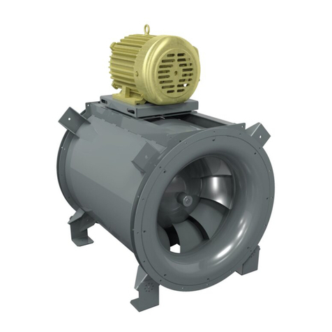
COOK JetStream User manual

1JET STREAM IO&M P0000313-000
®
JetStream
Tube Axial Fans/Jet Tunnel Fan
INSTALLATION, OPERATION AND MAINTENANCE MANUAL
Receiving and Inspection
Carefully inspect the fan and accessories for any dam-age
and shortage immediately upon receipt of the fan.
• Turn the propeller by hand to ensure it turns freely and does
not bind
• Record on the Delivery Receipt any visible sign of damage
Handling
Lift JetStream fans by placing a sling around the fan hous-
ing or through lifting eyes.
NOTICE! Never lift by the motor or inlet/outlet silencers.
Storage
If the fan is stored for any length of time prior to installa-
tion, rotate the propeller several revolutions every three to ve
days. This keeps a coating of grease on all internal bearing
parts. Block propeller to prevent natural rotation and store it in
its original shipping crate and protect it from dust, debris and
weather.
Rotating Parts & Electrical Shock Hazard:
Fans should be installed and serviced by qualied person-
nel only.
Disconnect electric power before working on unit (prior to re-
moval of guards or entry into access doors).
Follow proper lockout/tagout procedures to ensure the unit
cannot be energized while being installed or serviced.
A disconnect switch should be placed near the fan in order
that the power can be swiftly cut o, in case of an emergency
and in order that maintenance personnel are provided com-
plete control of the power source.
Grounding is required. All eld-installed wiring must be com-
pleted by qualied personnel. All eld installed wiring must
comply with National Electric Code (NFPA 70) and all ap-
plicable local codes. Ensure the power supply (voltage, fre-
quency and current carrying capacity of wires) is in accor-
dance with the motor nameplate.
Fans and blowers create pressure at the discharge and vac-
uum at the inlet. This may cause objects to get pulled into the
unit and objects to be propelled rapidly from the discharge.
The discharge should always be directed in a safe direction
and inlets should not be left unguarded. Any object pulled
into the inlet will become a projectile capable of causing se-
rious injury or death.
When air is allowed to move through a non-powered fan, the
impeller can rotate, which is referred to as windmilling. Wind-
milling will cause hazardous conditions due to unexpected
rotation of components. Impellers should be blocked in posi-
tion or air passages blocked to prevent draft when working
on fans.
Friction and power loss inside rotating components will
cause them to be a potential burn hazard. All components
should be approached with caution and/or allowed to cool
before contacting them for maintenance.
Under certain lighting conditions, rotating components may
appear stationary. Components should be veried to be sta-
tionary in a safe manner, before they come into contact with
personnel, tools or clothing.
Failure to follow these instructions could result in death or
serious injury.
The attachment of roof mounted fans to the roof curb as well
as the attachment of roof curbs to the building structure must
exceed the structural requirements based on the environ-
mental loading derived from the applicable building code for
the site. The local code ocial may require variations from
the recognized code based on local data. The licensed engi-
neer of record will be responsible for prescribing the correct
attachment based on construction materials, code require-
ments and environmental eects specic to the installation.
This publication contains the installation, operation and
maintenance instructions for standard unit of the JetStream
Tube Axial Fans/Jet Tunnel Fan.
Carefully read this publication and any
supplemental documents prior to any
installation or maintenance procedure.
Loren Cook catalog, JetStream, provides additional infor-
mation describing the equipment, fan performance, available
accessories and specication data.
For additional safety information, refer to AMCA Publication
410 -96, Safety Practices for Users and Installers of Industrial
and Commercial Fans.
All of the publications listed above can be obtained from:
• lorencook.com
• 417-869-6474 ext. 166
For information and instructions on special equipment, con-
tact Loren Cook Company at 417-869-6474.
JetStream

2JET STREAM I0&M P0000313-000
Ceiling Mounted Spring Isolator Rubber-in-Shear Ceiling Isolator
Figure 2 - Ceiling Mount Isolators
Wiring Installation
Some fractional motors have to be removed in order to make
the connection with the terminal box at the end of the motor.
NOTICE! Follow the wiring diagram in the disconnect
switch and the wiring diagram provided with the mo-
tor. Correctly label the circuit on the main power box
and always identify a closed switch to promote safety
(i.e., red tape over a closed switch).
Direct Drive Fans
1. Pull the wire into the motor wiring box. Restrain the wire to
prevent it from being pulled into the shaft.
2. For nal connections, follow the wiring diagram provided
on the motor.
Final Installation Steps
1. Inspect fasteners and setscrews, particularly fan mount-
ing and then tighten according to Recommended Torque
for Setscrews/Bolts.
2. Inspect for correct voltage with voltmeter.
3. Ensure all silencers, wire guards and accessories are
installed.
4. Check the fan to see if it is a directional or reversible prop.
5. For directional fans: Test the fan to be sure the rotation
is the same as indicated by the arrow marked Rotation.
For Reversible fans: Test the fan to ensure proper rotation
for the correct airow direction.
NOTICE! Do not allow the fan to run in the wrong direc-
tion. This will overheat the motor and cause serious
damage. For 3-phase motors, if the fan is running in
the wrong direction, check the control switch. It is pos-
sible to interchange two leads at this location so that
the fan is operating in the correct direction.
Operation
Pre-Start Checks
1. Lock out all the primary and secondary power sources.
2. Inspect fasteners and setscrews, particularly those used
for mounting the unit, and tighten if necessary.
3. Inspect motor wiring.
4. Rotate the propeller to ensure it does not rub against the
housing.
5. Ensure fan, silencers, and wire guard are clean and free
of debris.
6. For directional fans: Test the fan to be sure the rotation
is the same as indicated by the arrow marked Rotation.
For Reversible fans: Test the fan to ensure proper rotation
for the correct airow direction.Restore power to unit.
Installation
Isolation Installation
To help prevent vibration and noise from being transferred to
the building, isolators are recommended.
Floor Mounted Spring Isolators
1. Mount fan on isolation base or rails (if supplied).
2. Elevate fan (or isolation base) to operating height and in-
sert blocks to hold in position.
3. Position isolators under the fan and vertically align by in-
serting leveling bolt through mounting holes in the fan or
the base. The isolator must be installed on a level surface.
4. Adjust the isolators by turning the leveling nut counter-
clockwise several turns at a time alternately on each iso-
lator until the fan weight is transferred onto the isolators
and the fan raises uniformly o the blocks. Then remove
the blocks.
5. Turn lock nut onto leveling bolt and secure rmly in place
against the top of the mounting ange or frame.
6. Secure isolators to mounting surface.
Spring Isolator Rubber-in-Shear Isolator
Figure 1 - Floor Mount Isolators
Floor Mounted Rubber-In-Shear (RIS) Isolators
1. Mount fan on isolation base or rails (if supplied).
2. Elevate fan to provide room to insert isolators between the
fan and foundation and block in position.
3. Position isolators under fan and secure bolts.
4. Remove blocks and allow fan to rest on oor. Isolators
must be installed on a level surface (leveling should not
be required).
5. Secure isolators to mounting surface.
Ceiling Mounted Spring and Rubber-in-Shear (RIS)Isola-
tors
1. Elevate fan to operating height and brace.
2. Attach threaded rod to overhead support structure directly
above each mounting hole. Rod should extend to within a
few feet of fan.
3. Attach isolator to end of threaded rod using a nut on each
side of isolator bracket.
4. Insert another section of threaded rod through the fan
mounting hole and isolator.
5. Attach two nuts to threaded rod in isolator.
6. Place adjusting nut and locking nut on threaded rod near
fan mounting bracket.
7. Alternately rotate adjusting nut at each mounting location
until the fan weight is uniformly transferred to the isolators.
Remove bracing.

3JET STREAM IO&M P0000313-000
Recommended Torque for Setscrews/Bolts (IN-LB)
Setscrews Hold Down Bolts
Size
Key Hex
Across
Flats
Recommended
Torque Size Recommended
Torque
Min. Max.
#8 5/64” 15 21 3/8”-16 324
#10 3/32” 27 33 1/2”-13 780
1/4 1/8” 70 80 5/8 ”-11 1440
5/16 5/32” 140 160 3/4”-10 2400
3/8 3/16” 250 290 7/8”-9 1920
7/16 7/32” 355 405 1”-8 2700
1/2 1/4” 560 640 1-1/8”-7 4200
5/8 5/16” 1120 1280 1-1/4”-7 6000
3/4 3/8” 1680 1920 - -
7/8 1/2” 4200 4800 - -
19/16” 5600 6400 - -
Start-Up
Ensure free rotation of the prop. Turn on the fan. In variable
speed units, set fan to its lowest speed and inspect for the fol-
lowing:
• Direction of rotation
• Excessive vibration
• Unusual noise
• Bearing noise
• Improper motor amperage or voltage
NOTICE! If a problem is discovered, immediately shut
o the fan. Lock out all electrical power and check for
the cause of the trouble. Refer to Troubleshooting.
Inspection
Inspection of the fan should be conducted at the rst 30
minute, 8 hour and 24 hour intervals of satisfactory opera-
tion. During the inspections, stop the fan and inspect as per
the following:
30 Minute Interval
Inspect bolts, setscrews and motor mounting bolts. Adjust
and tighten as necessary.
8 Hour Interval
Inspect bolts, setscrews and motor mounting bolts. Adjust
and tighten as necessary.
24 Hour Interval
Inspect bolts, setscrews and motor mounting bolts. Adjust
and tighten as necessary.
Wiring Diagrams
Single Speed, Single Phase Motor
T-
1
T-
4
Ground B
L2
L1
Ground A
Line
When ground is required, attach to ground A or B with No. 6 thread
forming screw. To reverse, interchange T-1 and T-4.
2 Speed, 2 Winding, Single Phase Motor
Ground A
Ground B
T-1
T-
4
Low Speed
High Speed
L1
L2
Line
When ground is required, attach to ground A or B with No. 6 thread
forming screw. To reverse, interchange T-1 and T-4 leads.
Single Speed, Single Phase, Dual Voltage
Ground B
J-10
T-5
Ground A
Link A
Link B
Low Voltage
Line
L2
L1
Ground A
Link A
and B
L1
L2
Line
Ground B
T-5
J-10
When ground is required, attach to ground A or B with No. 6 thread
forming screw. To reverse, interchange T-5 and J-10 leads.
3 Phase, 9 Lead Motor
456
1
7
2
8
3
9
L1L2L3
456
789
12 3
L1L2L3
Low Voltage
208/230 Volts
High Voltage
460 Volts
3 Phase, 9 Lead Motor
Y-Connection
7
1
6789
456
12 3
Low Voltage
208/230 V
olts
High V
oltage
460 Volts
8
2
4
9
3
5
L
1
L
3
L
2
L1L3
L2
3 Phase, 9 Lead Motor
Delta-Connection
To reverse, interchange any two line leads.
2 Speed, 1 Winding, 3 Phase Motor
Motor
1
2
3
4
5
6
Together
High Speed
Line
L1
L2
L
3
1
2
3
4
5
6
Open
Low Speed
Line
L1
L2
L3
Motor
To reverse, interchange any two line leads. Motors require magnetic
control.
2 Speed, 2 Winding, 3 Phase
L
1
T
1
T
2
T
3
Low Speed
Low Speed
Low Speed
High Speed
High Speed
High Speed
Motor
T
13
T
12
T
11
L
2
Line
L
3
To reverse, High Speed: interchange leads T11 and T12; Low
Speed: interchange leads T1 and T2; Both Speeds: interchange any
two line leads.

4JET STREAM I0&M P0000313-000
3. Remove the propeller retaining plate from the motor shaft.
4. Remove the propeller from the motor shaft.
5. Unhook the motor leads.
6. Remove motor from the motor mounting plate. Inspect all
hardware and replace worn components.
7. Attach the replacement motor to the motor mounting plate.
Tighten hold-down bolts to the proper torque.
8. See motor label for correct motor wiring.
9. Replace propeller on motor shaft in the location initially
marked in step 2.
10. Check for proper rotation. To reverse, see previous wiring
diagrams.
11. Replace the retaining plate and propeller side silencer that
was initially removed to gain access to the motor.
After 24 hours of continuous operation, tighten the set-
screws to the appropriate torque. This assures the full locking
of the inner race to the shaft. Ensure the socket key or driver
is in good condition with no rounded corners. The key should
be fully engaged in the setscrew and held squarely to prevent
the rounding out of the setscrew socket when applying maxi-
mum torque.
Motor Replacement Precautions
• If the shaft is dropped and bent, it may cause unbalanced
operation of the fan
• When handling the propeller separately from the shaft,
place a support through the hub for lifting, making sure not
to injure the nished bore of the propeller
• Never allow the propeller to rest its entire weight on the
blades. The propeller and shaft can be lifted by slings
around the shaft on each side of the propeller so the propel-
ler is supported by its hub
• If using a chain to lift the propeller, make sure there is suf-
cient padding on the shaft and propeller. This pre-vents the
scoring of the shaft or injury to the propeller. The chain or
cable should be spread with timbers, or braced by some
other method to prevent damage to the propeller side plates
Maintenance
Establish a schedule for inspecting all parts of the fan. The
frequency of inspection depends on the operating conditions
and location of the fan.
Inspect fans exhausting corrosive or contaminated air within
the rst month of operation. Fans exhausting contaminated air
(airborne abrasives) should be inspected every three months.
Clean the propeller and air inlets if material build-up is ex-
cessive. Excessive build-up can cause imbalance and failure
of the propeller. Always clean the entire propeller as partial
cleaning will cause imbalance and fan failure.
Regular inspections are recommended for fans exhausting
non-contaminated air.
It is recommended the following inspections be con-
ducted twice per year:
• Inspect bolts and setscrews for tightness. Tighten as
necessary
• Inspect for cleanliness and clean as necessary. Removing
dust and grease on motor housing assures proper motor
cooling and proper air performance. Clean using com-
pressed air and/or dry rags. No liquid/solvent cleaners are
to be used.
• Inspect Inlet/outlet guards and the silencers. Remove any
build up or debris.
Motor Bearings
Motors are provided with prelubricated bearings. Any lubri-
cation instructions shown on the motor nameplate supersede
instructions below.
Motor bearings without provisions for relubrication will op-
erate up to 10 years under normal conditions with no mainte-
nance. In severe applications, high temperatures or excessive
contaminates, it is advisable to have the maintenance depart-
ment disassemble and lubricate the bearings after 3 years of
operation to pre-vent interruption of service.
For motors with provisions for relubrication, follow intervals
of the table below.
Relubrication Intervals
Service
Conditions
NEMA Frame Size
Up to and
including 184T 213T–365T 404T and larger
1800
RPM
and
less
Over
1800
RPM
1800
RPM
and
less
Over
1800
RPM
1800
RPM
and less
Over 1800
RPM
Standard 3 yrs. 6 months 2 yrs. 6 months 1 yr. 3 months
Severe 1 yr. 3 months 1 yrs. 3 months 6 months 1 month
Motors are provided with a polyurea mineral oil NGLI #2
grease. All additions to the motor bearings are to be with
a compatible grease such as Exxon Mobil Polyrex EM and
Chevron SRI.
The above intervals should be reduced to half for vertical
shaft installations.
Motor Services
Should the motor prove defective within a one-year period,
contact your local Loren Cook representative or your nearest
authorized electric motor service representative.
Motor Replacement
1. Remove the propeller side silencer to gain access to the
motor.
2. Mark the location of the propeller in the housing.

5JET STREAM IO&M P0000313-000
Troubleshooting
Problem and Potential Cause
Low Capacity or Pressure:
• Incorrect direction of rotation. Make sure the fan rotates in
same direction as the arrows on the rotation label
• Poor fan inlet conditions.
• Improper propeller alignment
Excessive Vibration and Noise:
• Damaged or unbalance propeller
• Speed too high
• Incorrect direction of rotation. Make sure the fan rotates in
same direction as the arrows on the rotation label
• Fan surge
Overheated Motor:
• Motor improperly wired
• Incorrect direction of rotation. Make sure the fan rotates
in same direction as the arrows on the motor or belt drive
assembly
• Cooling air diverted or blocked
• Improper inlet clearance
• Incorrect fan RPMs
• Incorrect voltage
Parts List
JetStream
1
2
3
4
5
6
7
Part
No. Description
1Inlet/Outlet Guard
2Inlet/Outlet Silencer
3Housing
4Cast Aluminum
Propeller
5Prop Retaining Plate
6Bushing
7Motor

6JET STREAM I0&M P0000313-000
or Replacement
(This page is intentionally left black)

7JET STREAM IO&M P0000313-000
or Replacement
(This page is intentionally left black)

8JET STREAM I0&M P0000313-000
Limited Warranty
Loren Cook Company warrants that your Loren Cook fan was manufactured free of defects in materials and workmanship, to the extent stated herein. For a
period of one (1) year after date of shipment, we will replace any parts found to be defective without charge, except for shipping costs which will be paid by you.
This warranty is granted only to the original purchaser placing the fan in service. This warranty is void if the fan or any part thereof has been altered or modied
from its original design or has been abused, misused, damaged or is in worn condition or if the fan has been used other than for the uses described in the com-
pany manual. This warranty does not cover defects resulting from normal wear and tear. To make a warranty claim, notify Loren Cook Company, General Oces,
2015 East Dale Street, Springeld, Missouri 65803-4637, explaining in writing, in detail, your complaint and referring to the specic model and serial numbers of
your fan. Upon receipt by Loren Cook Company of your written complaint, you will be notied, within thirty (30) days of our receipt of your complaint, in writing, as
to the manner in which your claim will be handled. If you are entitled to warranty relief, a warranty adjustment will be completed within sixty (60) business days of
the receipt of your written complaint by Loren Cook Company. This warranty gives only the original purchaser placing the fan in service specically the right. You
may have other legal rights which vary from state to state. For fans provided with motors, the motor manufacturer warrants motors for a designated period stated
in the manufacturer’s warranty. Warranty periods vary from manufacturer to manufacturer. Should motors furnished by Loren Cook Company prove defective dur-
ing the designated period, they should be returned to the nearest authorized motor service station. Loren Cook Company will not be responsible for any removal
or installation costs.
Corporate Oces: 2015 E. Dale St. Springeld, MO 65803
Phone 417-869-6474 | Fax 417-862-3820 | lorencook.com
August 2021
Table of contents
Other COOK Fan manuals
Popular Fan manuals by other brands

Kruger
Kruger TDA General instructions

Trotec
Trotec TTW 25000 S operating instructions

Swann
Swann Retro SFA12610 manual

Monte Carlo Fan Company
Monte Carlo Fan Company 3TAHR56 D Series Owner's guide and installation manual

Uberhaus
Uberhaus PRO FE45-H1 Operator's manual

CTC Union
CTC Union Clatronic VL 3601 instruction manual