4PROPELLER WALL IO&M B51091-003
30 Minute Interval
Inspect bolts, setscrews, and motor mounting bolts.
Adjust and tighten as necessary.
8 Hour Interval
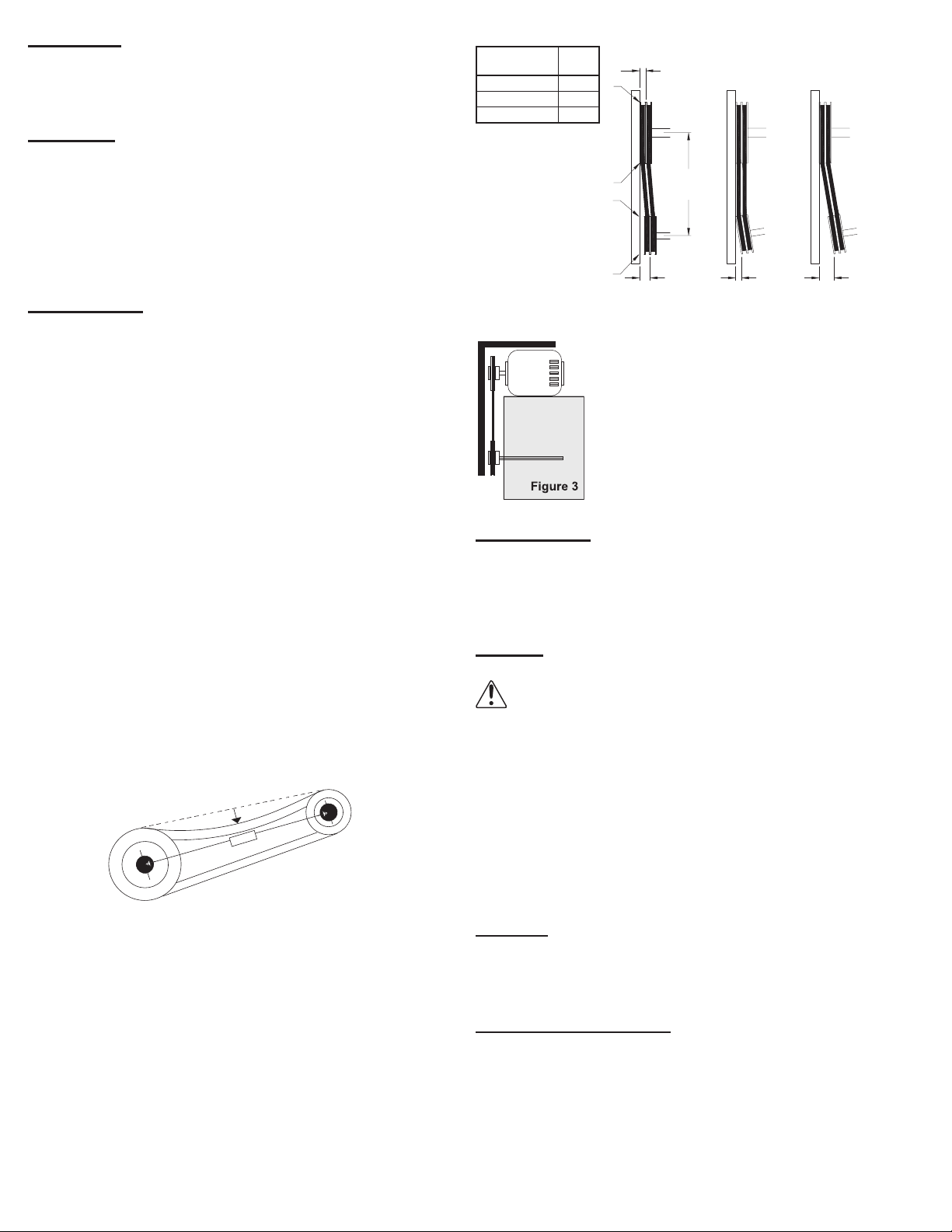
Inspect belt alignment and tension. Adjust and tighten as
necessary.
24 Hour Interval
Inspect belt tension. Adjust and tighten as necessary.
Maintenance
Establish a schedule for inspecting all parts of the fan.
The frequency of inspection depends on the operating
conditions and location of the fan.
Inspect fans exhausting corrosive or contaminated air
within the rst month of operation. Fans exhausting con-
taminated air (airborne abrasives) should be inspected ev-
ery three months. Clean the propeller and air inlets if ma-
terial build-up is excessive. Excessive build-up can cause
imbalance and failure of the propeller. Regular inspections
are recommended for fans exhausting non-contaminated
air. It is recommended the following inspections be con-
ducted twice per year.
• Inspect bolts and setscrews for tightness. Tighten as
necessary
• Inspect belt wear and alignment. Replace worn belts with new
belts and adjust alignment as needed. See Belt and Pulley
Installation, on page 2
• Bearings should be inspected as recommended in the
Conditions Chart, page 5
• Inspect for cleanliness. Clean exterior surfaces only.
Removing dust and grease on motor housing assures proper
motor cooling
Lubricants
Loren Cook Company uses petroleum lubricant in a lith-
ium base conforming to NLGI grade 2 consistency. Other
grades of grease should not be used unless the bearings
and lines have been ushed clean. If another grade of
grease is used, it should be lithium-based.
An NLGI grade 2 grease is a light viscosity, low-torque,
rust-inhibiting lubricant that is water resistant. Its tempera-
ture range is from -30°F to +200°F and capable of intermit-
tent highs of +250°F.
Motor Bearings
Motors are provided with prelubricated bearings. Any
lubrication instructions shown on the motor nameplate su-
persede instructions below.
Direct Drive 1050/1075, 1200, 1300 and 1500 RPM units
use a prelubricated sleeve bearing that has a oil saturated
wicking material surrounding it. The initial factory lubrica-
tion is adequate for up to 10 years of operation under nor-
mal conditions. However, it is advisable to add lubricant
after 3 years. Use only LIGHT grade mineral oil or SAE
10W oil up to 30 drops. If the unit has been stored for a
year or more it is advisable to lubricate as directed above.
For units in severe conditions, lubrication intervals should
be reduced to half.
Motors without sleeve bearings (as described above) will
have grease lubricated ball or roller bearings. Motor bear-
ings without provisions for relubrication will operate up to
10 years under normal conditions with no maintenance.
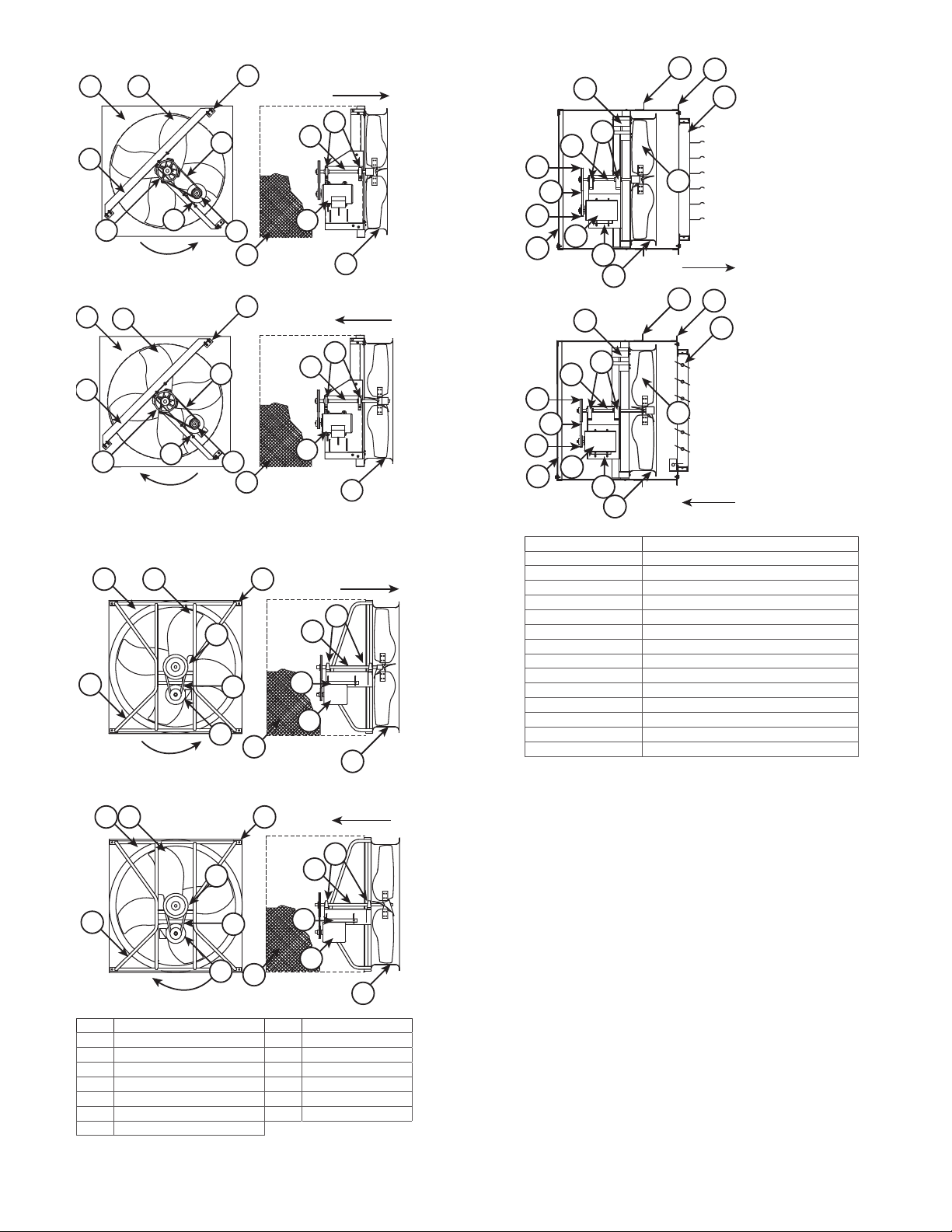
Typical Installation
Refer to page 7.
Final Installation Steps
1. Inspect fasteners and setscrews, particularly fan
mounting and bearing fasteners, and tighten accord-
ing to the recommended torque shown in the table be-
low, Recommended Torque for Setscrews/Bolts.
2. Inspect for correct voltage with voltmeter.
3. Ensure all accessories are installed.
4. Test the fan to be sure the rotation is the same as indi-
cated by the arrow marked Rotation.
Operation
Pre-Start Checks
1. Lock out all the primary and secondary power sources.
2. Inspect fasteners and setscrews, particularly those used for
mounting the unit, and tighten if necessary.
3. Inspect belt tension and pulley alignment. (Remember, if
belt tension is correct, a loud squeal occurs as the fan in-
creases to full power.)
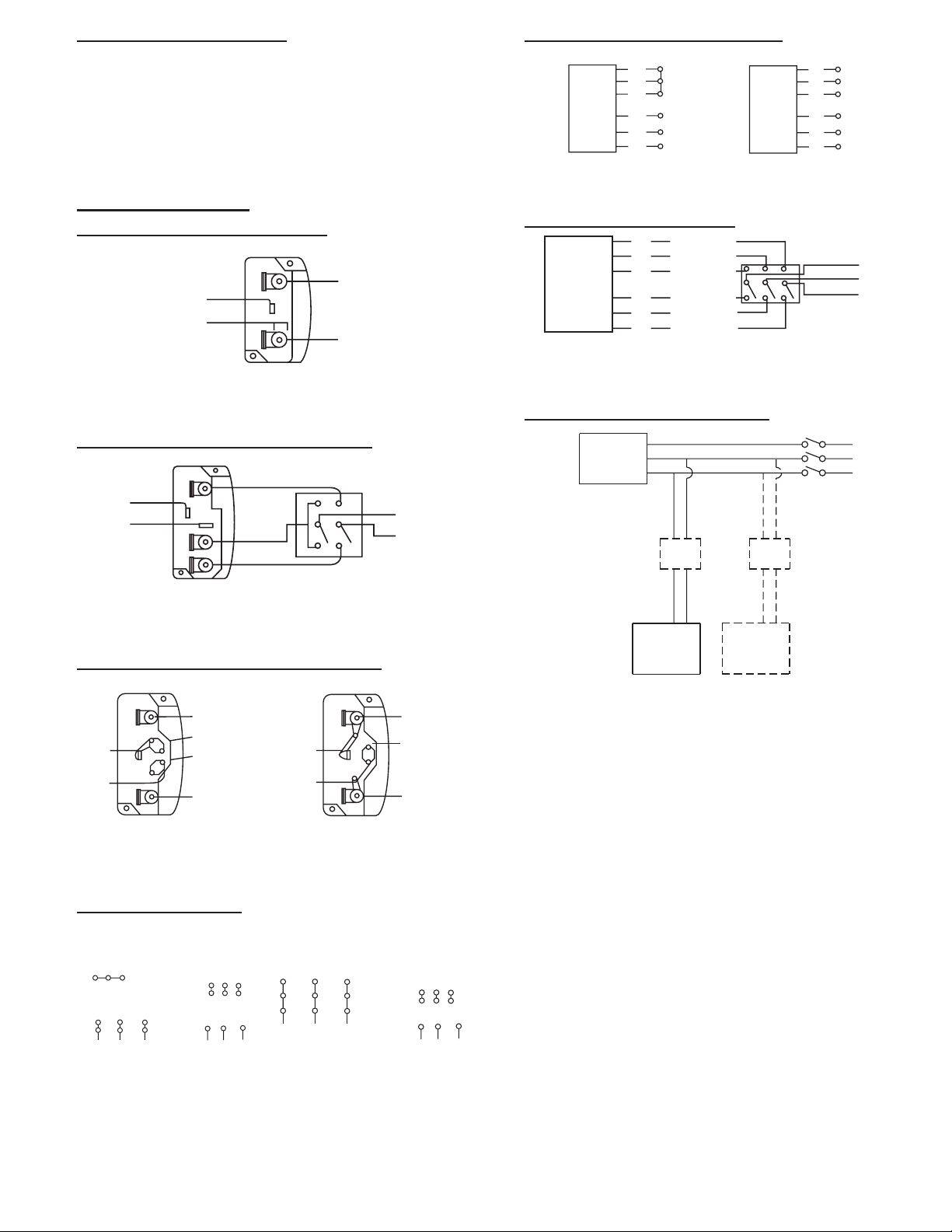
4. Inspect motor wiring.
5. Ensure the belt touches only the pulleys.
6. Rotate the prop to ensure it does not rub against the venturi.
7. Ensure fan and ductwork are clean and free of debris.
8. Test the fan to ensure the rotation of the propeller is the
same as indicated by the rotation label.
9. Close and secure all access doors.
10. Restore power to unit.
Start Up
Turn the fan on. In variable speed units, set the fan to its
lowest speed. Inspect for the following:
• Direction of rotation
• Excessive vibration
• Unusual noise
• Bearing noise
• Improper belt alignment or tension (listen for a continuous
squealing noise)
• Improper motor amperage or voltage
NOTICE! If a problem is discovered, immediately shut
o the fan. Lock out all electrical power and check for
the cause of the trouble. Refer to Troubleshooting.
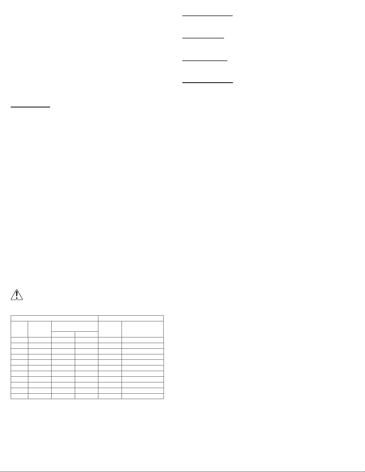
Recommended Torque for Setscrews/Bolts (IN-LB)
Setscrews Hold Down Bolts
Size
Key Hex
Across
Flats
Recommended
Torque Size Recommended
Torque
Min. Max.
#8 5/64” 15 21 3/8”-16 324
#10 3/32” 27 33 1/2”-13 780
1/4 1/8” 70 80 5/8”-11 1440
5/16 5/32” 140 160 3/4”-10 2400
3/8 3/16” 250 290 7/8”-9 1920
7/16 7/32” 355 405 1”-8 2700
1/2 1/4” 560 640 1-1/8”-7 4200
5/8 5/16” 1120 1280 1-1/4”-7 6000
3/4 3/8” 1680 1920 - -
7/8 1/2” 4200 4800 - -
19/16” 5600 6400 - -
Inspection
Inspection of the fan should be conducted at the rst 30
minute, 8 hour and 24 hour intervals of satisfactory op-
eration. During the inspections, stop the fan and inspect as
per the following directions.