American Coolair Corp. Form No. 610-40-13 (August 2021) 1
Operation and Maintenance Instructions for Type S
Manual & Motor Operated Wall Shutters
Single-Panel Motor Operated
Shutter Models S24 - S36
Manually Operated Shutter
Models S24 - S60
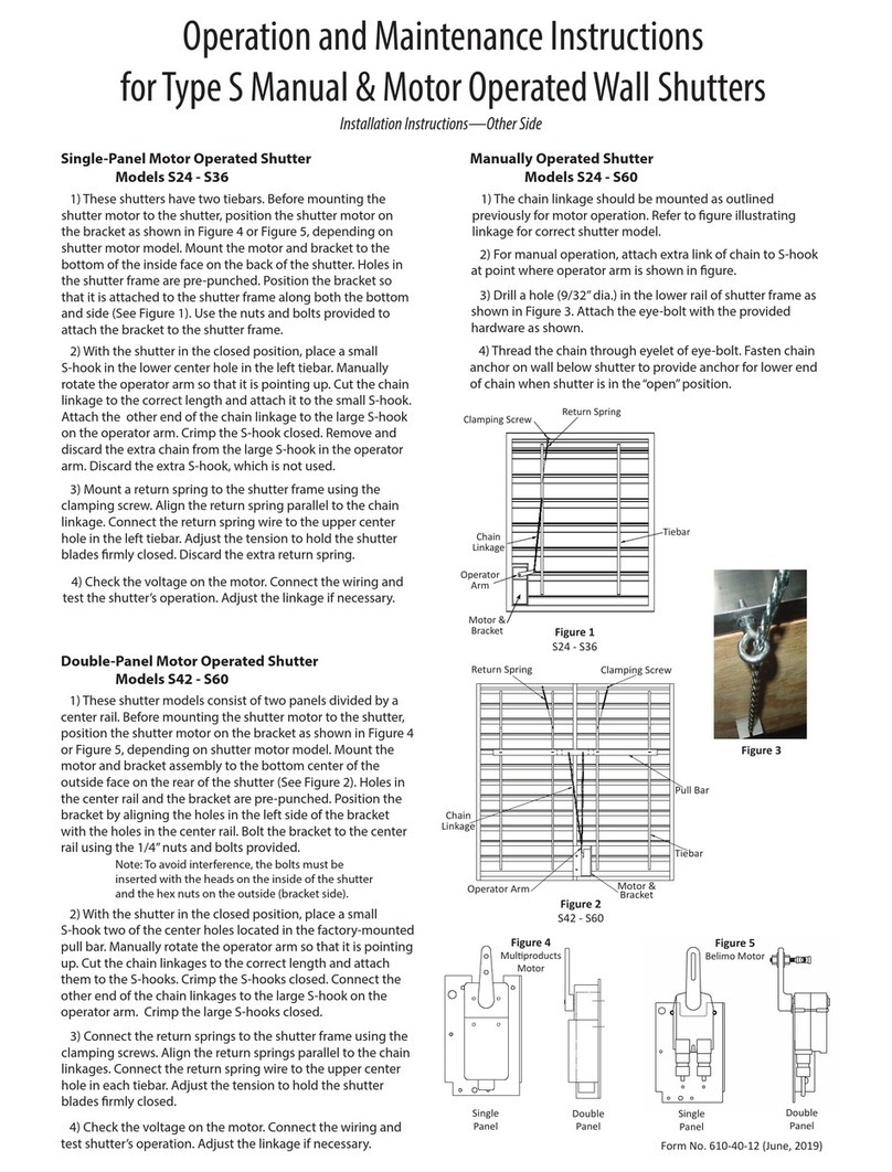
1) These shutters have two tiebars. Before mounting the
shutter motor to the shutter, position the shutter motor on
the bracket as shown in Figure 4 or Figure 5, depending on
shutter motor model. Mount the motor and bracket to the
bottom of the inside face on the back of the shutter. Holes in
the shutter frame are pre-punched. Position the bracket so
that it is attached to the shutter frame along both the
bottom and side (Figure 1). Use the nuts and bolts provided
to attach the bracket to the shutter frame.
2) With the shutter in the closed position, place a small
S-hook in the lower center hole in the left tiebar. Manually
rotate the operator arm so that it is pointing up. Cut the
chain linkage to the correct length and attach it to the small
S-hook. Attach the other end of the chain linkage to the
large S-hook on the operator arm. Crimp the S-hook closed.
Remove and discard the extra chain from the large S-hook in
the operator arm. Discard the extra S-hook, which is not
used.
3) Mount a return spring to the shutter frame using the
clamping screw. Align the return spring parallel to the chain
linkage. Connect the return spring wire to the upper center
hole in the left tiebar. Adjust the tension to hold the shutter
blades firmly closed. Discard the extra return spring.
4) Check the voltage on the motor. Connect the wiring and
test the shutter’s operation. Adjust the linkage if necessary.
Double-Panel Motor Operated
Shutter Models S24 - S36
1) These shutter models consist of two panels divided by a
center rail. Before mounting the shutter motor to the
shutter, position the shutter motor on the bracket as shown
in Figure 4 or Figure 5, depending on shutter motor model.
Mount the motor and bracket assembly to the bottom center
of the outside face on the rear of the shutter (See Figure 2).
Holes in the center rail and the bracket are pre-punched.
Position the bracket by aligning the holes in the left side of
the bracket with the holes in the center rail. Bolt the bracket
to the center rail using the 1/4” nuts and bolts provided.
Note: To avoid interference, the bolts must be
inserted with the heads on the inside of the shutter
and the hex nuts on the outside (bracket side).
2) With the shutter in the closed position, place a small S-
hook in two of the center holes located in the factory-
mounted pull bar. Manually rotate the operator arm so that it
is pointing up. Cut the chain linkages to the correct length
and attach them to the S-hooks. Crimp the S-hooks closed.
Connect the other end of the chain linkages to the large S-
hook on the operator arm. Crimp the large S-hooks closed.
3) Connect the return springs to the shutter frame using the
clamping screws. Align the return springs parallel to the
chain linkages. Connect the return spring wire to the upper
center hole in each tiebar. Adjust the tension to hold the
shutter blades firmly closed.
4) Check the voltage on the motor. Connect the wiring
and test shutter’s operation. Adjust the linkage if necessary.
1) The chain linkage should be mounted as outlined
previously for motor operation. Refer to figure
illustrating linkage for correct shutter model.
2) For manual operation, attach extra link of chain to S-
hook at point where operator arm is shown in figure.
3) Drill a hole (9/32” dia.) in the lower rail of shutter
frame as shown in Figure 3. Attach the eye-bolt with the
provided hardware as shown.
4) Thread the chain through eyelet of eye-bolt. Fasten
chain anchor on wall below shutter to provide anchor for
lower end of chain when shutter is in the “open”
position.
Return Spring
Clamping Screw
Chain Linkage
Operator Arm
Motor &
Bracket
Tiebar
Figure 1
S24 - S36
Figure 2
S42 - S60
Figure 3
Manual Chain Eyebolt
Return Spring
Clamping Screw
Pull Bar
Tiebar
Chain Linkage
Operator Arm
Motor &
Bracket
Figure 4
Multiproducts Motor
Figure 5
Belimo Motor
Clockwise Motor
Rotation
Orange Side
Facing Out
Single Panel
Mount Holes
Double Panel
Mount Holes


