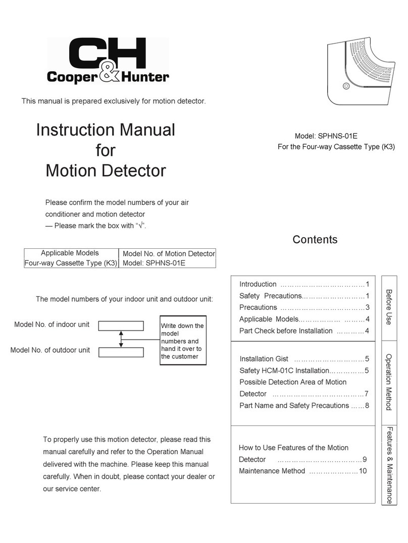
Cooper & Hunter SPHNS-S01E Instruction Manual

1.
1
DO NOT install the indoor unit, outdoor unit, controller and cable at places such as;
1. Where there is oil vapor and the oil is dispersed.
2. Where hot springs are located nearby (in a sulfuric environment).
3. Where generation, flowing, staying or leaking of flammable gas is detected.
4. Where the sea is located nearby (in the salty environment).
5. An acid or alkaline environment.
DO NOT install the indoor unit, outdoor unit, controller and cable within approximately 3 meters
from strong electromagnetic wave radiators such as medical equipment. In case that the controller
is installed in a place where there is electromagnetic wave direct-radiation, shield the controller
and cables by covering with the steel box and running the cable through the metal conduit tube.
In case that there is electric noise at the power source for the indoor unit, provide a noise filter.
1. Safety Summary
DANGER
DO NOT pour water into the Motion. This product is equipped with electrical parts that may cause serious
electrical shock when in contact with water.
WARNING
DO NOT perform installation and electrical wiring connection by yourself. Contact your distributor or dealer
and ask them for installation work and electrical wiring by service person.
CAUTION
The box □ is for checking work .Check the box after checkig.
(Model: SPHNS-S01E )
IMPORTANT:
READ AND UNDERSTAND THIS MANUAL BEFORE USING THIS CONTROLLER . KEEP THIS MANUAL FOR
FUTURE REFERENCE.
IMPORTANT NOTICE:
No part of this manual may be reproduced without written permission.
Signal words (DANGER, WARNING, and CAUTION) are used to identify levels of hazard seriousness. Definitions of
identifying hazard levels are provided below with their respective signal words.
DANGER
WARNING
CAUTION
: Immediate hazards which WILL result in severe personal injury or death.
: Hazards or unsafe practices which COULD result in severe personal injury or death.
: Hazards or unsafe practices which COULD result in minor personal injury or product or property
damage.
NOTE: Useful information for operation and/or maintenance.
2. Installation
[2.1 Selection of Installation Place]
□1)
●
●where the air from the air conditioner is directly discharged, keep a distance at least 1.2M from
air conditioner.
Select a suitable place for handling and determining the installation place of the Motion with the customer's
acceptance. Do not install the Motion at places such as;
●where place close to light.
where children can reach.
Motion Installation & Maintenance Manual

2
[2.2 Before Installation]
□
This package contains the following parts.
Installation Spot check specification……1
User Manual……1
[2.3 Installation Procedures]
□Insert the edge of the slotted
screwdriver into the groove at the
bottom of the holding bracket, push
and turn the slotted screwdriver and
then remove the controller from the
holding bracket.
1)
Slotted Screw
Figure Seen from
The Side Groove
Part for Removing
Motion
Approx. 6mm Slotted Screw Driver
□2) Attach the Motion to the holding bracket and connect the cable as follows.
(A) Fix the holding bracket onto the fixed
surface with screws
(accessory), including but not limited to
reinforced concrete wall and wooden board.
Please choose the best fixation method
based on actual situation.
Assembling screw M4*5/8in.(16mm)……2
1)
Motion……1
(B)Peel the insulation at the end of the cable
and clamp the M3 solderless terminals.
The Motion can project a standard rectangle in the condition of the area is large enough. The
connection between sensor and LED is perpendicular to the long side. Please according to actual
situation to choose suitable installation form.
●
Ceiling Mounted Wall Mounted
Keep the rotating part parallel
to front surface. The hight of
roof should be 8.2~9.8ft.
(2.53m).
Keep the rotating part fixed in
wall mounting angle. The hight of
fixed point should be 8.2~9.8ft.
(2.5~3m).Please refer chapter 4
and make sure DSW setting is
correct.
Note:
Rotating part should
be pressed until
steady and without
shaking.
□2) Select a suitable Installation form for maximum range of monitoring.

3
The max indoor units depends on remote controller.
number of
Remote control Switch
REMOCON REMOCON
of Indoor Unit
Terminal Board Terminal Board
Screws
Twist Pair Cable with Shield Tube: 1P-18AWG(0.75MM²)or more
ATTENTION:Always make sure to turn off the power supply of
the indoor unit when performing electrical wiring. Performing
electrical wiring work with the power on can damage the circuit
boards of the indoor unit and the remote control switch.
Electrical Box Electrical Box
of Indoor Unit
M3.5
Screws
M3.5
3. Electrical Wiring
Motion
(C)Fix the decorative ring to the holding
bracket and make sure the special
positioning feature in right position like
figure above.
(D)Fix the front panel to the holding bracket and
make sure the positioning feature in a straight line.
CAUTION
Refer to the Technical Catalog provided with each indoor unit when performing electrical wiring work between the remote control switch and
indoor units for setting the refrigerant cycle number and the indoor unit address.
Use a 22 to 18AWG(0.3 to 0.75mm ) cable for connecting. The maximum total cable length is 98.4ft.(30m).If the total cable length exceeds 98.4ft.(30m), use a twist pair cable
with shield tube(1P-18AWG(0.75mm ) or more).In that case, the maximum total cable length is up to 1640.4ft.(500m).If using in combination with the control timer, the
allowable total cable length is up to 328.1ft.(100m).The use of a cable other than specified above can cause of malfunction due to the effects of noise.
2
2
Keep a distance more than 12in.(0.3m) between the transmission line (remote control switch cable and transmission wires) and power source of the
indoor units. If not, the air-conditioner may not operate properly or malfunction may occur due to effect of power source noise.
In case of simultaneously controlling multiple indoor units, set the refrigerant cycle numbers and addresses of the indoor units without overlapping.
No gap shall exist between the remote control switch cable and hole of the remote control switch case. If there is a gap, cover the gap with vinyl tape.
If not, malfunction may occur due to entrance of water droplets or insects.

4
If LED flash at stable frequency, it means that Motion has failed.
6.. Specification
Diameter 3-30/32in.(100mm) Hight 1-7/64in.(28mm)
Operating Temperature range 32℉(0℃) to 95℉(35℃); Indoor use only
Connection
Dimensions
Wall mounted
7.. Guideline for Detection Area
Ceiling mounted
4. DSW Setting
DSW1
Default Setting
Note:
The default setting of
DSW2 is corresponding
to ceiling mounted. If wall
mounted is needed,
DSW2-2 should be ON.
ON ON
5.. Fault Information
1 Motion per wired remote group
DSW2
Default Setting
T00528Q 05.2022 V00
8.2~9.9ft.
26.3ft.
13.13ft.
8.2~9.9ft.
7-7/8in.
18.7ft.
3.3ft.
17.4ft.
18.7ft.
18.4ft.
20.4ft.
Other manuals for SPHNS-S01E
1
Other Cooper & Hunter Security Sensor manuals
Popular Security Sensor manuals by other brands

System Sensor
System Sensor CO1224T Frequently asked questions

ETC
ETC Echo Dual Tech installation guide

GST
GST DC-M9103 quick start guide

PCB Piezotronics
PCB Piezotronics 8120F-410A Installation and operating manual

Floodstop
Floodstop FS34NPT Installation and operating manual

VIDICON
VIDICON STAR installation instructions

BGB
BGB 33333-A instruction manual

PCB Piezotronics
PCB Piezotronics ICP 356A32 Installation and operating manual

Sensitron
Sensitron SMART3H-FM LITE instruction manual

Visonic
Visonic Logica installation instructions

Aura Light
Aura Light Kvill CE installation manual

Bornack
Bornack RAILSTOP RS S06 user manual