Cooper Crouse-Hinds CEAG AB 05 Ex-nR Series User manual

Bulkhead lighting fitting for hazardous
areas for zone 2 / 22
Serie: AB 05 Ex-nR
Explosionsgeschützte
Wand und Deckenleuchte
für Zone 2 / 22
Serie: AB 05 Ex-nR
Hublots pour atmosphères explosives
les zones 2 / 22
Série: AB 05 Ex-nR
GHG 860 7002 P0002 (a)
&=7HQWRQiYRGNSRXåLWtVLPåHWHY\åiGDW
YHVYpPPDWHĜVNpPMD]\FHXSĜtVOXãQp R
]DVWRXSHQtVSROHþQRVWL&RRSHU&URXVH
+LQGV&($*YHYDãt]HPL
'.0RQWDJHYHMOHGQLQJHQNDQRYHUVWWHVWLO
DQGUH(8VSURJRJUHNYLUHUHV RV'HUHV
&RRSHU&URXVH+LQGV&($*OHYHUDQG¡U
((QFDVRQHFHVDULRSRGUiVROLFLWDUGHVX
UHSUHVHQWDQWH&RRSHU&URXVH+LQGV&($*
HVWDVLQVWUXFFLRQHVGHVHUYLFLRHQRWURLGLRPD
GHOD8QLRQ(XURSHD
(676HGDNDVXWXVMX HQGLWRPDULLJLNHHOHV
Y}LWHNVLGDRPDULLJLVDVXYDVWDVMDRPDVHVW
&RRSHU&URXVH+LQGVL&($*HVLQGXVHVW
),17DUYLWWDHVVDWlPlQNl\WW|R MHHQNllQQ|V
RQVDDWDYLVVDWRLVHOOD(8QNLHOHOOl7HLGlQ
&RRSHU&URXVH+LQGV&($*HGXVWDMDOWDQQH
*5ǼĮȞȤȡİȚĮıșİȚİIJĮȡĮıȘIJȦȞȠįȘȖȚȦȞȤȡȘıİ
ȦȢıİĮȜȜȘȖȜȦııĮIJȘȢǼǼʌȠȡİȚȞĮȗȘIJȘșİȚĮʌȠ
IJȠȞǹȞIJȚʌȡȠıȦʌȠIJȘȢ&RRSHU&URXVH
+LQGV&($*³
+$NH]HOpVL~WPXWDWyWD]DGRWWRUV]iJ
Q\HOYpQD&RRSHU&URXVH+LQGV&($*FpJ
HO\LNpSYLVHOHWpQLJpQ\HO HWLPHJ
,6HGHVLGHUDWHODWUDGX]LRQHGHOPDQXDOH
RSHUDWLYRLQXQDOWUDOLQJXDGHOOD&RPXQLWj
(XURSHDSRWHWHULF LHGHUODDOYRVWUR
UDSSUHVHQWDQWH&RRSHU&URXVH+LQGV&($*
/7âLRVQDXGRMLPRLQVWUXNFLMRVLãYHUVWRVƳ-njVǐ
JLPWąMąNDOEąJDOLWHSDUHLNDODXWLDWVDNLQJRMH
&RRSHU&URXVH+LQGV&($*DWVWRY\EHMHVDYR
ãDO\MH
/9âRHNVSOXDWƗFLMDVLQVWUXNFLMXYDOVWVYDORGƗ
YDUDWSLHSUDVƯWMXVXYDOVWVDWELOGƯJDMƗ&RRSHU
&URXVH+LQGV&($*SƗUVWƗYQLHFƯEƗ
0-LVWJƫXMLWROEXGDQLOPDQZDOILOOLQJZD
QD]]MRQDOLWDJƫRPPLQJƫDQGLUUDSSUHĪHQWDQW
WD&RRSHU&URXVH+LQGV&($*ISDMMLĪRP
1/,QGLHQQRRG]DNHOLMNNDQGHYHUWDOLQJYDQ
GH]HJHEUXLNVLQVWUXFWLHLQHHQDQGHUH(8WDDO
ZRUGHQRSJHYUDDJGELM8Z&RRSHU&URXVH
+LQGV&($*YHUWHJHQZRRUGLJLQJ
36HIRUQHFHVViULDDWUDGXomRGHVWDV
LQVWUXo}HVGHRSHUDomRSDUDRXWURLGLRPDGD
8QLmR(XURSHLDSRGHVROLFLWDODMXQWRGRVHX
UHSUHVHQWDQWH&RRSHU&URXVH+LQGV&($*
3/1LQLHMV]ąLQVWUXNFMrREV XJLZRGSRZLHGQLHM
ZHUVMLMĊ]\NRZHMPRĪQD]DPyZLüZ
SU]HGVWDZLFLHOVWZLHILUP\&RRSHU&URXVH
+LQGV&($*QDGDQ\NUDM
6(Q|YHUVlWWQLQJDYGHQQDPRQWDJHRF
VN|WVHOLQVWUXNWLRQWLOODQQDW(8VSUnNNDQYLG
EH RYEHVWlOODVIUnQ(U&RRSHU&URXVH
+LQGV&($*UHSUHVHQWDQW
6.7HQWRQiYRGQDREVOX X9iPYR9DãRP
URGQRPMD]\NXSRVN\WQH]DVW~SHQLHVSRORþQRVWL
&RRSHU&URXVH+LQGV&($*YR9DãHMNUDMLQH
6/21DYRGLOD]DXSRUDERY9DãHPMH]LNX
OD NR]D WHYDWHSULSULVWRMQHP]DVWRSQLãWYX
SRGMHWMD&RRSHU&URXVH+LQGV&($*Y9DãL
GUåDYL
Betriebsanleitung
Operating instructions
Mode d’emploi
COOPER Crouse-Hinds GmbHCOOPER Crouse-Hinds GmbH
COOPER Crouse-Hinds GmbH
Neuer Weg - Nord 49
D 69412 Eberbach / Germany
Fone +49 (0) 6271/806 - 500
Fax +49 (0) 6271/806 - 476
Internet: http://www.CEAG.de
E-Mail: [email protected]

2Cooper Crouse-Hinds
N
L
N
PE
L
Fig. 1 Netzanschluss / mains connection / Raccordement au secteur
Kennzeichnung Gas
Leuchtmittel
der Leitungen
Ambient temperature
Wandmontage Einführung unten
Deckenmontage
Deckenmontage
Wandmontage Einführung unten
Mindesttemperaturbeständigkeit
Wall assembly entry from below
Montage mural, introduction par le bas
Ceiling assembly
Montage au plafond
Wall assembly entry from below
Montage mural, introduction par le bas
Ceiling assembly
Montage au plafond
Température ambiante
Umgebungstemperatur
der Einführungen
Explosion category gas
Marquage selon gaz
Kennzeichnung Staub
Explosion category dust
Marquage selon poussière
Lampe
Lampe
Minimum temperature resistance
Résistance minimale aux températures
of cables
câbles of cable entries
Entrées de câble
II3 DExtc IIIC IP66 T125°C Dc
II 3 D Ex tc IIIC IP66 T125°C Dc
II3 DExtc IIIC IP66 T125°C Dc
II3 DExtc IIIC IP66 T 100°C Dc
II3 DExtc IIIC IP66 T125°C Dc
II3 DExtc IIIC IP66 T140°C Dc
HSE/HST 70 W
HSE/HST 70 W
HME 80 W
HME 80 W
Glühlampe 60W
Glühlampe 60W
Glühlampe 100W
Glühlampe 100W
Glühlampe 200W
Glühlampe 200W
80
95
80
90
50
65
60
75
75
90
85
115
80
95
80
95
50
65
60
75
75
90
100
115
70
85
70
85
55
70
55
70
70
85
70
85
70
85
70
85
55
70
55
70
70
85
80
95
-25 < Ta< +40
-25 < Ta< +551)
-25 < Ta< +40
-25 < Ta< +551)
-25 < Ta< +40
-25 < Ta< +55
-55 < Ta< +40
-55 < Ta< +55
-55 < Ta< +40
-55 < Ta< +551)
-55 < Ta< +401)
-55 < Ta< +551)
Energiesparlampe
Typ PL 23 W
Energiesparlampe
Typ PL 23 W
°C
°C
°C
°C
°C
II 3 G Ex nR IIC T4 Gc
II 3 G Ex nR IICT4 Gc
II 3 G Ex nR IIC T4 Gc
II 3 G Ex nR IIC T3 Gc
II 3 G Ex nR IICT3 Gc
284,00
380,00
85,00
175,00
230,00
253,00
L
N
Z
PE
BLp N
L
N
Z
PE
HSE /
HST
HME
Bei Wandmontage Leitungseinführung von unten/
For wall assembly cable entry from bottom/
En cas de montage mural : introduction du câble par le bas
Fig. 2 Maße in mm/ Dimensions in mm/ Dimensions en mm
Fig. 3 Tabelle 1
table 1
tableau 1
1) Für Temperaturwerte über 70° C wärmebeständige Leitungseinführungen verwenden.
Für Temperaturwerte über 80° C zusätzlich wärmebeständige Anschlussleitungen verwenden.
Use heat-resistant cable entries for temperature values above 70° C.
Use heat-resistant connecting cables for temperature values above 80° C
Pour les températures supérieures à 70 ° C, utilisez des entrées de câble résistant à la chaleur.
Pour les températures supérieures à 80 ° C, utilisez en plus des câbles de raccordement résistant à la chaleur
Prüfanschluss M 6

Cooper Crouse-Hinds 3
1. Sicherheitshinweise:
Zielgruppe:
Elektrofachkräfte gem. EN 60079-14 und unter-
wiesene Personen.
- Diese Leuchte darf nicht in explosions-
gefährdeten Bereichen der Zone 0 , 1und
Zone 20 , 21 eingesetzt werden.
- Die Anforderungen der EN 60079-31 u.a. in
Bezug auf übermäßige Staubablagerungen und
Temperatur, sind vom Anwender zu beachten.
- Die auf der Leuchte angegebenen technischen
Daten sind zu beachten!
- Umbauten oder Veränderungen an der Leuchte
sind nicht zulässig!
- Die Leuchte ist bestimmungsgemäß in unbeschä-
digtem und einwandfreiem Zustand zu betreiben!
- Als Ersatz dürfen nur Originalteile von Cooper
Crouse-Hinds (CCH)/CEAG verwendet werden!
- Reparaturen, die den Explosionsschutz
betreffen, dürfen nur von CCH/CEAG oder einer
qualifizierten „Elektrofachkraft“ durchgeführt
werden!
Beachten Sie die nationalen Unfallverhütungs- und
Sicherheitsvorschriften und die nachfolgenden
Sicherheitshinweise, die in dieser Betriebsanleitung
mit einem ( ) gekennzeichnet sind!
Beachten Sie die Warnschilder auf der Leuchte:
"Nicht unter Spannung öffnen".
"Nach dem Abschalten 10 Minuten vor dem Öffnen
warten".
"Nach Wartungsarbeiten alle Dichtungen wieder
Anbringen".
3. Normenkonformität
Das Betriebsmittel ist gemäß DIN EN ISO 9001
entwickelt, gefertigt und geprüft worden.
Es entspricht den aufgeführten Normen, in der
separat beigelegten Konformitätserklärung.
94/9/ EG: Geräte und Schutzsysteme zur
bestimmungsgemäßen Verwendung in explosions-
gefährdeten Bereichen.
4 Verwendungsbereich
Die Leuchte ist zum Einsatz in explosions-
gefährdeten Bereichen der Zonen 2 oder 22 gemäß
EN 60079-10 geeignet!
5. Installation
5.1 Allgemein
Für das Errichten / Betreiben sind die relevanten
nationalen Vorschriften sowie die allgemein
anerkannten Regeln der Technik maßgebend.
Unsachgemäße Installation / Betrieb der Leuchte
kann zum Verlust der Garantie führen.
Transport und Lagerung der Leuchte ist nur in
Originalverpackung und der angegebenen Lage
gestattet!
Achten Sie auf Beschädigungen der Glasoberfläche
während der Montage oder Reparatur! Abrieb oder
Sandstrahlen kann die mechanische Festigkeit
aufheben!
5.2 Montage
Montagemaße: siehe Fig. 2
Zubehör für die Montage: siehe CCH-Katalog
Bei Wandmontage Kabeleinführung von unten.
Die drei Befestigungslaschen sind für Schrauben mit
einem Durchmesser vom 8 mm und entspre-
chenden Unterlegscheiben vorgesehen.
Das Gehäuse darf nur an den vorgesehenen
Befestigungspunkten eben aufliegen und ver-
windungsfrei befestigt werden.
Bei übermäßigem Anziehen kann das Gerät
beschädigt werden.
5.3 Kabel-und Leitungseinführungen
(KLE); Verschlussstopfen
Die Leitungen, Leitungseinführungen und
Veschlussstopfen müssen für die Zündschutzart der
Leuchte zugelassen sein und der
Mindestemperaturbeständigkeit in Abhängigkeit des
Leuchtmittels der Fig. 3 Tabelle 1 entsprechen.
Alle nicht benutzten metrischen CEAG / Cooper
Crouse-Hinds KLE sind mit dem bescheinigten
Verschluss für metrische KLE zu verschließen, um
die Schutzart herzustellen (siehe technische Daten).
Die für die eingesetzten KLE maßgebenden
Montagerichtlinien sind zu beachten.
Bei übermäßigem Anziehen kann die Schutzart
beeinträchtigt werden.
Achtung: Beim Anziehen der Hutmutter der Metall -
KLE ist die Verschraubung mit einem geeigneten
Werkzeug gegen Verdrehen zu sichern.
Zugbelastete Anschlussleitungen sind mit geeigneten
Maßnahmen zu entlasten.
5.3.15.3.1
5.3.15.3.1
5.3.1 „nR“„nR“
„nR“„nR“
„nR“ SchwadensicherSchwadensicher
SchwadensicherSchwadensicher
Schwadensicher (Zone 2)(Zone 2)
(Zone 2)(Zone 2)
(Zone 2)
Es ist sicherzustellen, dass durch, z.B. Einsatz von
ausreichend dichten Kabel und Leitungen, die „nR“
Eigenschaften erhalten bleiben. (siehe auch IEC/EN
60079-14).
Werden die im Auslieferzustand vorhandenen KLE
durch andere KLE ersetzt, ist vor Inbetriebnahme
generell eine Überprüfung der „nR“ Eigenschaften
erforderlich.
Eine Überprüfung der Schwadensicherheit kann
entsprechend Abschnitt 9 erfolgen.
5.3.25.3.2
5.3.25.3.2
5.3.2 „t“ Staub (Zone 22)„t“ Staub (Zone 22)
„t“ Staub (Zone 22)„t“ Staub (Zone 22)
„t“ Staub (Zone 22)
Werden die im Auslieferzustand vorhandenen KLE
durch andere KLE ersetzt, müssen KLEs und
Verschlussstopfen in Übereinstimmung mit IEC
60079-31 verwendet werden.
5.4 Öffnen und Schließen der
Leuchte /
Elektrischer Anschluss
5.4.1 Allgemein
Der elektrische Anschluss der Leuchte darf nur
durch Elektrofachpersonal erfolgen.
5.4.2 Öffnen der Leuchte
Die 6 Gehäuse-Kombischrauben lösen und Oberteil
aufklappen.
Die Schutzfolie auf dem Metallreflektor entfernen.
5.4.3 Elektrischer Anschluss
Die Anschlussleitung durch die Kabel und Leitungs-
einführung einführen.
Bei ausschneidbaren Dichtungseinsätzen ist
sicherzustellen, dass der Einsatz ordnungsgemäß
dem Leitungsdurchmesser angepasst wird.
Zur Sicherstellung der erforderlichen
Mindestschutzart sind die KLE fest anzuziehen.
Bei übermäßigem Anziehen kann die Schutzart
beeinträchtigt werden.
Die Anschlussleitung, muss entsprechend dem
Einsatz der Leuchte, den Temperaturanforderungen
von Fig. 3, Tabelle 1 entsprechen.
Mit dem Klebeband auf der Keramik-Lampen-
fassung sind Silikonschläuche befestigt.
- Klebeband auf der Keramik-Lampenfassung
entfernen.
Die Silikonschläuche über die Anschlussleiter
schieben.
Anschlussleitung gemäß Klemmenbeschriftung und
Schaltbild anschließen.
Zur Aufrechterhaltung der Zündschutzart
ist der Leiteranschluss mit besonderer
Sorgfalt durchzuführen.
Die Isolation muss bis an die Klemme
heranreichen.
Der Leiter selbst darf nicht beschädigt sein.
Die minimale und maximale anschließbaren
Leiterquerschnitte beachten (siehe technische
Daten).
Bei der Verwendung von mehr- oder fein-drähtigen
Anschlusskabel /-leitungen sind die Aderenden
entsprechend den geltenden nationalen und
internationalen Vorschriften zu behandeln (z.B.
Verwendung von Aderendhülsen).
Alle Schrauben und/oder Muttern der
Anschlussklemmen, auch die der nicht
Benutzten, sind fest anzuziehen.
2. Technische Daten, allgemein
EG-Baumusterprüfbe-
scheinigung: BVS 07 ATEX E151
Kennzeichnung nach 94/9 EG und Norm:
ATEX II 3 G Ex nR IIC T... °C Gc
II 3 D Ex tc IIIC IP66 T... °C Dc IP66
( Besondere Bedingungen siehe Fig. 3 Tabelle 1)
IEC Ex Prüfbescheinigung:
IECEx BVS 10.0071
Kennzeichnung nach IECEx:
IEXEx Ex nR IIC T... °C Gc
Ex tc IIIC IP66 T... °C Dc IP66
( Besondere Bedingungen siehe Fig. 3 Tabelle 1)
Schutzart nach EN 60529:IP 66
Lampe: Lampen mit Fassung E27
nach EN 60061-1
Schutzklasse
nach EN 61140: I
zul. Umgebungstemp.: Fig. 3 Tabelle 1
Bemessungsspannung : bis 230 V AC/DC
Gehäusematerial Leichtmetalldruckguss, mit
grauer Polyesterfarbe
Schutzglas Borosilikat
Lagertemperatur -55 °C bis + 60 °C
Klemmvermögen der Anschlussklemme:
1,5 mm² ... 4,0 mm²
Abmessungen: siehe Fig. 2
Prüfdrehmomente:
Gehäuseschrauben M8x40 10 Nm
Anschlussklemmen: 2,5 Nm
Kabel und
Leitungseinführungen: M20 x 1,5
M25 x 1,5
NPT Gewinde 1/2"
NPT Gewinde 3/4"
(Abhängig von der Bestellnummer)
(Anleitung der Leitungseinführungen beachten)
Temperaturbeständigkeit siehe Fig.3 Tabelle 1

4Cooper Crouse-Hinds
5.5 Leuchtmittel
Der für die Leuchte zugelassene Leuchtmitteltyp ist
an folgenden Stellen angegeben:
- Fig. 3 Tabelle 1 dieser Betriebsanleitung
- Typenschild der Leuchte
- Klebeband auf der Keramik-Lampenfassung
5.5.1 Einsetzen der Lampe
Es dürfen nur solche Lampen verwendet
werden, die für diese Leuchte zugelassen sind
(siehe technische Daten und Typenschild)!
Die Lampe muss fest in die Lampenfassung
eingeschraubt werden. Achten Sie auf vollständige
Einschraubtiefe, damit es zu keinen Funken oder
anderen unzulässigen Betriebszuständen führen
kann! Schützen Sie sich gegen Glasbruch der Lampe
beim Einschrauben!
5.6 Schließen der Leuchte:
Alle Fremdkörper aus dem Gerät entfernen.
- Auf den richtigen Sitz des Gehäuseoberteils und
der Dichtungen achten.
- Alle Dichtungen müssen sauber und unbeschädigt
sein.
- Die Leuchte darf nicht beschädigt sein.
- Alle 6 Gehäuse-Kombischrauben diagonal,
gleichmäßig anziehen. (Prüfdrehmoment siehe
Technische Daten).
Bei übermäßigem Anziehen kann die Schutzart
beeinträchtigt werden.
6. Inbetriebnahme
Vor Inbetriebnahme des Betriebsmittels sind die in
den einzelnen nationalen Bestimmungen genannten
Prüfungen durchzuführen. Außerdem ist vor der
Inbetriebnahme die korrekte Funktion und Installation
des Betriebsmittels in Übereinstimmung mit dieser
Betriebsanleitung und anderer anwendbaren
Bestimmungen zu überprüfen.
Achtung: Es dürfen nur komplett bescheinigte Geräte
in Betrieb genommen werden.
Unsachgemäße Installation und Betrieb der Gehäuse
kann zum Verlust der Garantie führen.
10 Entsorgung / Wiederver-
wertung
Bei der Entsorgung des Betriebsmittels sind die jeweils
geltenden nationalen Abfallbeseitigungsvorschriften zu
beachten.
Programmänderungen und -ergänzungen sind vorbehal-
ten.
- Die Leuchte darf nur verschlossen
betrieben werden.
-Es wird empfohlen (siehe auch IEC/EN 60079-14)
generell, um Sicherzustellen, dass die konstruktive
Schwadensicherheit nicht durch die Installation
beeinträchtigt wurde, vor Inbetriebnahme eine
Prüfung auf Schwadensicherheit durchzuführen
(siehe Kapitel 9).
7. Instandhaltung / Wartung
Warnung:
Betriebsmittel vor der Wartung / Reparatur
spannungsfei schalten.
Achtung Verbrennungsgefahr:
Bevor die Leuchte geöffnet wird, muss diese nach
dem Ausschalten erst 10 Minuten abkühlen.
Nach Wartung alle Dichtunge wieder anbringen.
Halten Sie die für die Instandhaltung, Wartung und
Prüfung von explosionsgeschützten Betriebsmitteln
geltenden Bestimmungen z.B. IEC 60079-17 ein!
7.1 Wartung / Wiederkehrende
Prüfungen
Die Wartungsintervalle richten sich nach den
Umgebungsbedingungen und den Betriebszeiten. Die
in der IEC 60079-17 enthaltenen Empfehlungen für
wiederkehrende Prüfungen sind zu beachten.
Im Rahmen der Wartung / Inspektion sind vor allem
die Teile, von denen die Zündschutzart abhängt, auf
Beschädigungen zu prüfen z.B.:
- Schutzschläuche über den Anschlussleitungen.
- Gehäuse und Schutzglas auf Risse!
- Dichtungen von Leuchte und Kabel und Leitungs-
einführungen!
- Leitungseinführungen müssen korrosionsfrei sein!
- Klemmen und Verschlussstopfen auf festen Sitz!
- Beachten Sie die Wechselintervalle gemäß Vorgabe
der Lampenhersteller!
Lampentypen müssen gemäß Vorgabe sein!
Wird die Leuchte zu Wartungszwecken oder zum
Lampenwechsel geöffnet, ist sicherzustellen, dass
die „nR“ Eigenschaften nicht beeinträchtigt
wurden. Dies kann z.B durch Überprüfung der
Schwadensicherheit entsprechend Abschnitt 9
erfolgen.
7.27.2
7.27.2
7.2 LampenwechselLampenwechsel
LampenwechselLampenwechsel
Lampenwechsel
Für die Lampenwechselintervalle gelten die
Empfehlungen der Lampenhersteller.
Leuchte spannungsfrei schalten oder sicherstellen,
dass keine explosionsfähige Atmosphäre vorhanden
ist.
Öffnen und Schließen der Leuchte siehe Abschnitt
5.4. War die Leuchte zuvor in Betrieb, diese erst
nach einer Wartezeit von 10 Minuten öffnen.
Evt. vorhandene Staubablagerungen entfernen.
Einsetzen der Lampe siehe Abschnitt 5.5.
Nach dem Lampenwechsel ist sicherzustellen, dass
die „nR“ Eigenschaften nicht beeinträchtigt wurden.
Dies kann z.B. durch Überprüfung der Schwaden-
sicherheit entsprechend Abschnitt 9 erfolgen.
Fig.A Unterdruckprüfung
beim Typ Ex nR
= zulässiger Bereich
Z
300
150
0
0
80
Pa
s
Z
8 Reparatur / Instandsetzung /
Änderungen
8.1 Allgemein
Beachten sie die nationalen Bestimmungen!
(z.B. IEC 60079-17)
Instandsetzungsarbeiten / Reparaturen
dürfen nur unter Verwendung von CEAG /CCH
Originalersatzteilen vorgenommen werden.
Vor dem Austausch oder der Demontage von
Einzelteilen ist folgendes zu beachten:
Sicherstellen, dass keine explosionsfähige
Atmosphäre vorhanden ist.
Schalten Sie das Betriebsmittel vor dem Öffnen oder
vor Instandhaltungsarbeiten erst spannunsfrei!
Öffnen und Schließen der Leuchte siehe Abschnitt 5.4.
Verwenden Sie nur Originalersatzteile.
Bei Schäden an dem Gehäuse der Leuchte ist nur
ein Austausch des kompletten Betriebsmittel
zulässig. Im Zweifelsfalle ist das Betriebsmittel an
COOPER Crouse-Hinds zur Reparatur zurückzugeben.
War die Leuchte zuvor in Betrieb, diese erst nach
einer Wartezeit von 10 Minuten öffnen.
Reparaturen, die den Explosionsschutz
betreffen, dürfen nur von CCH oder einer
qualifizierten Elektrofachkraft in Übereinstimmung
mit national geltenden Regeln durchgeführt werden.
Umbauten oder Änderungen am Betriebsmittel sind
nicht gestattet.
Nach Reparatur oder Instandsetzungs-arbeiten ist
sicherzustellen, dass die „nR“ Eigenschaften nicht
beeinträchtigt wurden.
Dies kann z.B. durch Überprüfung der Schwaden-
sicherheit entsprechend Abschnitt 9 erfolgen.
Prüfanschluss M 6
9 Prüfung der
Schwadensicherheit
Alle Verschlussschrauben sowie KLE müssen
korrekt angezogen sein.
Übermäßiges Anziehen der Schraubelemente kann
die Gewinde zerstören.
Prüfgerät an den Prüfanschluss (Gewindebohrung
M6) der Leuchte anschließen (siehe Fig. A).
Die in IEC 60079-15 angegebenen Werte sind für die
Prüfung zu verwenden (siehe Fig. A).
Prüfanschluss wieder verschließen.

Cooper Crouse-Hinds 5
1. Safety instructions:
The operations must be carried out by electrical
suitably trained in hazardous area with knowledge
of increased safty explosion protection
IEC 60079-14.
- The light fitting is not suitable for use in
hazardous areas of zone 0, 1and 20, 21 .
The requirements of the EN 60079-31 regarding
excessive dust deposits and temperature to be
considered from the user.
- The technical data indicated on the light fitting
are to be observed!
- Changes of the design and modifications to the
light fitting are not permitted!
- The light fitting shall be operated as intended
and in undamaged and perfect condition!
- Only genuine Cooper Crouse-Hinds (CCH)/
CEAG spare parts may be used for replacement!
- Repairs may only be carried out by CCH/
CEAG or a qualified “electrician”!
- Observe the national safety rules and
regulations for prevention of accidents and the
following safety instructions which are marked with
an ( ) in these operating instructions!
- Do not keep these operating instructions inside
the light fitting during operation!
- Observe the warning signs on the light fitting:
„Do not open when under voltage“.
„Wait 10 minutes before opening after switching off“
„Replace all seals after maintenance work“.
3. Conformity with standards
It has been designed, manufactured and tested
according to the state of the art and to
DIN EN ISO 9001.
The apparat is conform to the standards specified
in the EC-Declaration of conformity, enclosed
separately.
94/9/ EC: Equipment and protective systems
intendet for use in potentially explosive
atmospheres.
4 Field of application
The light fitting is intended for use in potentially
explosive atmospheres in zones 2 and zones 22 in
accordance with IEC 60079-10.
The light fitting can be used in inside- or outside to
light areas with potentially explosive atmospheres.
5. Installation
5.1 General
For the mounting and operation, the respective
national regulations as well as the general rules of
engineering will have to be observed.
The improper installation and operation of lights
fittings may result in the invalidation of the
guarantee.
Transport and storage only original packaging in a
closed and try room!
Observe far any cracks or damage in housing and
glass!
Don´t damage the fire-finish of the glass
adquired during moulding (abrasions, sanding, etc.)
that can weaking their mechanical functions.
5.2 Mounting
Mounting dimensions: see Fig. 2
Additional mounting material see CCH catalogue.
For wall assembly cable entry from bottom.
The three fastening straps are designed for screws
with a diameter of 8 mm and the corresponding
washers.
The enclosure may only lie flat on and be fixed
torsion-free to the fastening points provided for
direct assembly.
Mind! Overtightening might damage the light fitting!
5.3 Cable entries (KLE);
blanking plugs
The cables, cable entries and blanking plugs
must correspond with the minimum temperature
resistance depending on the lamp in fig. 3 table 1.
Unused holes shall be closed with a certified
blanking plug in order to establish the minimum
protection category.
The operating instruction for the cable glands used
must be observed.
Overtightening might impair the protection category.
Attention: It must be ensured that during thigtening of
the cap nut, not the complete cable entry starts
turning.
5.3.1 „nR“ Restricted breathing (Zone 2)(Zone 2)
(Zone 2)(Zone 2)
(Zone 2)
The „Restricted breathing (nR)" properties must be
preserved when, for example, using cables and
wires of sufficient diameter.
(see also IEC/EN 60079-14).
If the cable glands included in the scope of delivery
are replaced with other cable glands, the "nR"
properties must be checked before putting into
operation.
A restricted breathing test may be carried out as
per section 9.
5.3.1 „t“ Dust (zone 22)(zone 22)
(zone 22)(zone 22)
(zone 22)
If the cable glands included in the scope of delivery
are replaced with other cable glands, the cable
glands and blanking plugs must be used in
compliance with
IEC 60079-31.
5.4 Opening and closing the
light fitting/
Electrical connection
5.4.1 General
The electrical connection of the lamp must only
be established by qualified electricians.
5.4.2 Opening the light fitting
Unscrew the six housing-combi-screws.
The protective film on the metal reflector have to
removed.
5.4.3 Electrical connection
Insert the connection cable through the cable entry.
With sealing inserts that can be trimmed, ensure
that the insert is correctly adapted to the diameter
of the cable.
Excessive tightening may impare the protection
category.
Attention:
The opening of light fitting always shall be withoutThe opening of light fitting always shall be without
The opening of light fitting always shall be without
voltagevoltage
voltagevoltage
voltage.
Before the light fitting is opened it must be allowed
to cool down for 10 minutes after switching off.
Make sure that there is no explosive ambient
atmosphere when opening the equipment.
The cables must correspond with the minimum
temperature resistance depending on the lamp in fig.
3 table 1 and application.
Silicone tubes are stuck to the light fitting socket
with adhesive tape.
- Remove adhesive tape from the ceramic lamp
socket.
Push the silicone tubes over the connecting
wires.
Connect cable according to the terminal numbering
and circuit diagram.
The conductors shall be connected with special
care in order to maintain the explosion category.
The insulation of the conductors shall reach the
terminal.
The conductor itself shall not be damaged.
The connectible min. and max. conductor
cross-sections shall be observed (see
technical data).
If multi- or fine-wire connecting cables are used,
the wire ends will have to be handled in acc. with
the applicable national and international rules (e.g.
use of sleeves for strands).
All screws and/or nuts of the supply terminals, also
of those remaining vacant, shall be tightened down.
2. Technical data
EC type examination
certificate: BVS 07 ATEX E151
Category of application
acc to 94/9EG / :
ATEX II 3 G Ex nR IIC T... °C Gc
II 3 D Ex tc IIIC IP66 T..°C Dc IP66
( special conditions see Fig. 3 tabelle 1)
IEC Ex Certification of
conformity: IECEx BVS 10.0071
Category of application
acc to IEC Ex/ : Ex nR IIC T... °C Gc
Ex tc IIIC IP66 T..°C Dc IP66
( special conditions see Fig. 3 tabelle 1)
Protection acc. to EN 60529: IP 66
Lamps: Lampholder E27
acc. to EN 60061-1
Insulation class
acc to EN 61 140: I
max. permissible ambient
temperature: Fig. 3 table 1
Rated voltage: up to 230 V AC/DC/
Housing material: aluminium alloy pressure
coating grey
Protection glas: Borosilikat
Storage temp. orig packing:
-55 °C bis + 60 °C
Terminal capacity: 1,5 ... 4,0 mm²
Dimensions: see Fig. 2
Test torque:
cover bowl screws M8x40: 10 Nm
Terminals: 2,5 Nm
Cable entries (Ex-e): M20 x 1,5
M25 x 1,5
NPT Gewinde 1/2"
NPT Gewinde 3/4"
(Depend on ordernumber)
(observe operating instruction cable entries)
temperature resistants see Fig.3 Table 1

6Cooper Crouse-Hinds
8 Repair/Overhaul/
Modifications
8.1 General
The relevant national regulations which apply to the
maintenance/servicing of electrical apparatus in
explosive atmospheres, shall be observed.
(e.c. IEC 60079-17)
Repairs and overhaul may only be carried out with
genuine COOPER CROUSE-HINDS spare parts.
Before replacing or disassembling individual parts,
observe the following:
Disconnect the power supply to the equipment
before maintenance / repair.
Make sure that there is no explosive atmosphere
when opening the equipment.
See section 5.4 for notes on opening and closing the
lamp.
Only use original spare parts.
If the light fitting was previously in operation then
wait 10 mins. before opening.
Repairs that affect the explosion protection, may
only be carried out by COOPER CROUSE-HINDS or a
qualified electrician in compliance with the applicable
national rules.
Modifications to the device or changes to its design
are not permitted.
After carrying out repair or overhaul work, ensure
that the "nR" properties have not been affected.
This could be done by testing the restricted
breathing properties as per section 9, for example.
9 Testing the restricted
breathing properties
All screw plugs and cable glands must be correctly
tightened.
Overtightening the screw elements can destroy the
thread.
Connect the testing equipment to the test
connection (Screw plug M6) on the
light fitting (see Fig. A).
Use the values specified in IEC 60079-15 for the test
(see Fig. A).
Close the test connection again.
5.5 Lamps
Only lamps that are approved for this type of
lamp may be used (see Fig.3 table 1, type label of the
light fitting and label on the lamp holder).
5.5.1 Inserting the lamp
The lamp must be screwed tightly into the lamp
holder. Ensure it is screwed in fully so that no
sparks or other unauthorised operating states may
occur. Protect the glass on the lamp from breaking
when screwing in.
5.6 Closing the light fitting
Remove all foreign matirals from the light fitting.
- Pay attention to the correct fit of the enclosure top
part and the seals.
- All seals must be clean an undamaged.
- The light fitting may not be damaged.
- Tighten all 6 enclosure cobi.screws evenly
diagonally (test torque 10 Nm).
Overtightening might impair the protection
category!
6. Putting into operating
Prior to putting the apparatus into operation, the
tests specified in the relevant national regulations
shall be carried out.
Check the light fitting for its proper functioning and
installation in compliance with these operating
instructions and other applicable regulations!
Attention: Only fully certified equipment may be put
into operation.
Improper installation and operation of the lamp leads
to loss of the guarantee.
10 Disposal/Recycling
When the apparatus is disposed of, the respective
national regulations on waste disposal will have to
be observed.
Subject to modifications or supplement of the
product range.
- The light fitting may only be operated when
closed.
- It is generally recommended (see
IEC/EN 60079-14) that you ensure the restricted
breathing of the construction is not impaired during
installation and that you test the restricted breathing
properties before commissioning (see section 9).
7. Maintenance / Servicing
Warning:
Disconnect the power supply to the equipment before
maintenance / repair.
Before the light fitting is opened it must be
allowed to cool down for 10 minutes after switching
off.
All seals have to be re-attach after maintenance.
Observe the valid regulations for the repair,
maintenance and testing of explosion-protected
equipment, e.g. IEC 60079-17!
7.1 General Maintenance /
Inspection
The interval between maintenance depends upon the
ambient conditions and the hours of operation. The
recommendations given within IEC 60079-17 for
recurring checks must be observed.
Within the scope of the maintenance / inspection,
especially those parts on which the type of
protection depends must be checked for damage,
e.g.:
- Silicone tubes over the connecting cables.
- cable entries must be free from corrosion!
- Observe the intervals for changing as specified by
the lamp manufacturer!
Lamp types must be as specified!
If the light fittings is opened for maintenance
purposes or to replace the lamp, ensure that the
"nR" properties are not affected.
This could be done by testing the restricted
breathing properties as per section 9, for example.
7.27.2
7.27.2
7.2 Lamp changeLamp change
Lamp changeLamp change
Lamp change
The suggested interval between lamp changes given
by the lamp manufacturer should be followed.
Disconnect the power or ensure that no hazardous
atmosphere is present..
See section 5.4 for notes on opening and closing the
lamp. If the light fitting was previously in operation
then wait 10 mins. before opening.
See section 5.5 for notes on inserting the lamp.
After replacing the lamp, ensure that the "nR"
properties have not been affected.
This could be done by testing the restricted
breathing properties as per section 9, for example.
Fig.A Vacuum test
in type Ex nR
= acceptable range
Z
300
150
0
0
80
Pa
s
Z
Test connection M6

Cooper Crouse-Hinds 7
1. Consignes de sécurité
Pour le personnel électricien qualifié et le personnel
instruit suivant la règlementation légale, y compris
les normes respectives ainsi que, le cas échéant,
CEI 60079-14 pour apppareils électriques
utilisables en atmosphère explosive.
- Ce luminaire ne convient pas a l’emploi en
atmosphère explosive de zones 0,1 et zones 20, 21
- Les exigences des EN 60079-31 en ce qui
concerne des dépôts de poussière démesurés et
une température doivent être considérées par
I’utilisateur.
- Les caractéristiques techniques indiquées sur
le luminaire doivent être respectées!
- Il n’est pas permis de transformer ou de
modifier le luminaire!
- Le luminaire ne doit être exploité que pour la
fonction qui lui est dévolue et qu’en état intact et
parfait!
- Seules des pièces de rechange d’origine CCH/
CEAG doivent être employées pour le
remplacement!
- Des réparations ne doivent être exécutées que
par CEAG ou par un «électricien» qualifié!
- Veuillez respecter les prescriptions nationales
de sécurité et de prévoyance contre les accidents
ainsi que les consignes de sécurité qui sont
marquées d’un ( ) dans ce mode d’emploi!
- Tenez compte des panonceaux d’avertissement
sur le luminaire :
« Ne pas ouvrir sous tension ».
« Après extinction, attendre 10minutes avant
d’ouvrir ».
« Remettre tous les joints après les travaux de
maintenance ».
3. Conformité avec les normes
Les luminaire ont été conçues, fabriquées et
contrôlées suivant DIN EN ISO 9001.
Les luminairel sont conformes aux normes reprises
dans la déclaration de conformité, jointe
séparément.
94/9 CE: Appareils et systèmes de protection
destinés à être utilisés en atmosphère explosible.
De plus, ces fiches et prises correspondent à
d’autres exigences comme par ex. à ceux de la
directive “Compatibilité électromagnétique”
(2004/108/CEE).
4 Domaine d’utilisation
Les luminaire conviennent à l’emploi en les zones 2
et zones 22 d’une atmosphère explosive selon
CEI 60079-10!
5. Installation
5.1 Courant
Pour l’installation et l’exploitation d’appareils
électriques pour atmosphère explosive, la
règlementation nationale en vigueur ainsi que les
règles de la technique généralement reconnues
devront être respectées.
L’installation inadéquates de luminaire peuvent
entraîner la perte de la garantie.
Le transport et le stockage du luminaire ne sont
autorisés que dans l’emballage d’origine et dans la
position prescrite dans des locaux secs.
Veillez à ne pas endommager la surface de verre au
cours du montage ou des réparations. Le frottement
ou les projections de sable peuvent porter atteinte à
ses caractéristiques mécaniques.
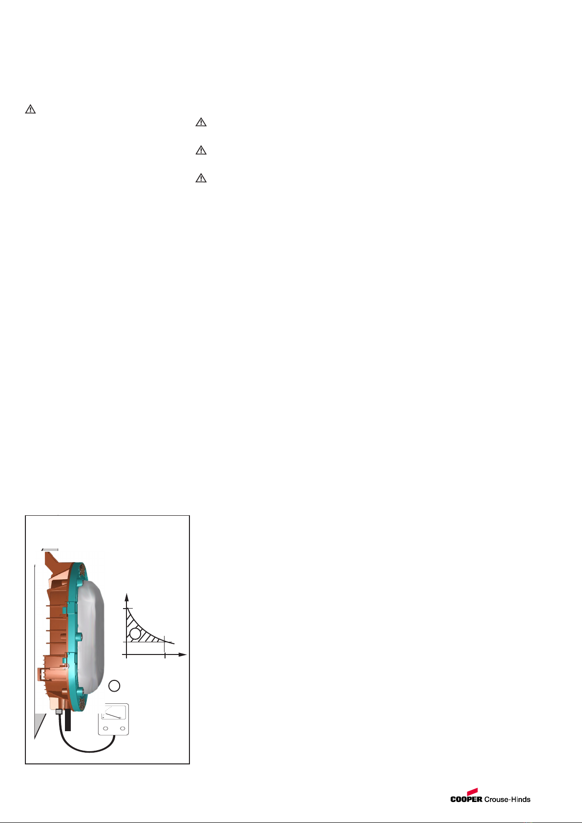
5.2 Montage
En cas de montage mural : introduction du câble
par le bas.
Les trois pattes de fixation sont prévues pour des
vis d’un diamètre de 8 mm avec des rondelles
appropriées.
En cas de montage direct, le boîtier doit reposer à
plat uniquement sur les points de fixation prévus et
doit être fixé sans torsion.
L’appareil peut être endommagé par un serrage
excessif.
5.3 Entrées de câble
Les câbles et entrées de câble doivent
correspondre à la résistance minimale aux
températures en fonction du luminaire de la Fig. 3
tableau 1.
Les câbles de raccordement soumis à la traction
doivent être soulagés par des mesures appropriées.
Pour le montage des entrées de câble pour le
raccordement au secteur, respectez les indications
du fabricant des joints et des entrées de câble
employés.
Les ouvertures de boîtier non utilisées doivent être
obturées avec les bouchons homologués appropriés.
Les entrées de câble et les bouchons doivent être
homologués pour le type de protection
antidéflagrante du luminaire !
5.3.15.3.1
5.3.15.3.1
5.3.1 „nR“ utilisation (Zones 2)„nR“ utilisation (Zones 2)
„nR“ utilisation (Zones 2)„nR“ utilisation (Zones 2)
„nR“ utilisation (Zones 2)
Il est de veiller à ce que, par exemple Suffisamment
dense de câbles et de fils, la „nR“ propriétés
intactes. (voir aussi l’IEC / EN 60079-14).
Sont disponibles dans la livraison KLE KLE
remplacés par d’autres, est mise en service il ya
une révision globale de la „nR“ propriétés
nécessaires.
Un réexamen de la sécurité andains peut
s’effectuer conformément à la section 9.
5.3.25.3.2
5.3.25.3.2
5.3.2 „t“ utilisation (Zones 22)„t“ utilisation (Zones 22)
„t“ utilisation (Zones 22)„t“ utilisation (Zones 22)
„t“ utilisation (Zones 22)
Sont disponibles dans la livraison KLE KLE
remplacés par d’autres, il faut KLEs et bouchon en
conformité avec IEC 60079-31 être utilisé.
5.4 Ouverture du dispositif/
Raccordement électriques
5.4.1 Courant
Le raccordement électrique du dispositif ne doit
se faire que par du personnel qualifié.
5.4.2 Ouvrir le luminaire
Le boîtier 6-break vis et ouvrir la coquille.
Le film de protection sur le métal Réflecteur
supprimer.
5.4.3 Raccordement électriques
Le câble de raccordement par le câble et le câble
en place.
Pour ausschneidbaren joint missions est de
s’assurer que l’utilisation correctement le fil de
diamètre adapté.
Afin d’assurer le minimum requis de protection de la
KLE serrer.
En cas de serrage peut être porté atteinte à la
protection.
Le câble de raccordement, doit être l’utilisation de
la lampe, les conditions de température de Fig 3, le
tableau 1.
Avec le ruban adhésif sur la lampe en céramique
sont les tubes de silicone fixé.
- De bande adhésive sur la douille en céramique
supprimer.
Les tuyaux en silicone sur la suite chef de glisser.
Câble de raccordement, conformément à l’étiquette
et de serrage schéma connecter.
Afin de maintenir la protection
est le chef de port, en particulier
De soin.
L’isolement doit être à la borne
heranreichen.
Le chef lui-même ne doit pas être endommagé.
Les minimum et maximum de connectables chef de
section (voir données techniques).
Lors de l’utilisation de plus-ou fin-drähtigen de
raccordement / fils de la veine, conformément aux
réglementations nationales et internationales en la
matière à traiter (par exemple, utiliser des embouts
de câble).
Toutes les vis et / ou écrous des
Bornes de connexion, y compris les non
Utilisés, sont les serrer.
1)1)
1)1)
1) Bei Leuchtenausführungen mit zwei Dichtungen in den
Spaltflächen müssen die Spalte nicht gefettet werden.
2. Caractéristiques techniques
Certificat d´essai CE: BVS 07 ATEX E151
Marquage selon directive 94/9/CE:
ATEX II 3 G Ex nR IIC T... °C Gc
II 3 D Ex tc IIIC IP66 T..°C Dc IP66
(Conditions particulières voir le Fig 3 tableau 1)
Certificat d´essai IEC EX: IECEx BVS 10.0071
(voir tableau 1)
Marquage selon directive IEC Ex:
Ex nR IIC T... °C Gc
Ex tc IIIC IP66 T..°C Dc IP66
(Conditions particulières voir le Fig 3 tableau 1)
Indice de protection selon:IP 66
Lampes: culot E27
EN 60061-1
Classe d’isolation selon
EN 61 140: I
Température ambiante.: Fig. 3 tableau 1
Tension nominale: jusqu´a 230 V AC/DC
Matériau du boîtier coulé sous pression en
alliage léger, avec
peinture polyester, coloris gris
Verre de protection borosilicate
Température de stockage dans
l’emballage original -55 °C - + 60 °C
Capacité de serrage des bornes:
1,5 mm² ... 4,0 mm²
Dimensions: voir Fig. 2
Torques d’essai:
Vis de cuve M8x40 10 Nm
de bornes: 2,5 Nm
Entrées de câble (Ex.e): M20 x 1,5
M25 x 1,5
NPT fils 1/2"
NPT fils 3/4"
(En fonction de la référence)
Résistance minimale aux températures Fig. 3 tableau 1

8Cooper Crouse-Hinds
9 Évacuation des déchets/
Recyclage
Lors de l’évacuation de ce matériel électrique, la
règlementation nationale respective en vigueur devra
être respectée.
Sous réserve de modification ou de supplément de
cette série de produits.
7 Maintien
Avertissement :
Mettez les appareils hors tension avant d’effectuer
la maintenance / la réparation.
Attention risque de brûlures :
Avant ouverture du luminaire, il convient de le laisser
refroidir pendant 10 minutes après extinction.
En ouvrant les appareils, veillez à ce qu’ils ne se
trouvent pas dans une atmosphère explosive.
Pour la remise en état, la maintenance et le
contrôle des moyens d’exploitation antidéflagrants,
respectez les dispositions en vigueur telles que
CEI 60079-17.
7.1 Entretien
Dans le cadre de la maintenance / inspection sont
avant tout les parties, dont la fonction de
protection, de dommages à examiner, par
exemple:
- Sur la protection des tuyaux de raccordement.
- Boîtier et sur la protection des larmes de verre!
- Joints de feu et de câbles et de câble!
- De câble doivent être sans corrosion!
- Bouchon de fermeture et de bornes fixes à
examiner!
- De respecter les intervalles, conformément à
l’objectif des fabricants d’ampoules!
Type de lampes doivent être, conformément à
l’objectif!
7.27.2
7.27.2
7.2 Changement de lampe
Pour la lampe de remplacement, les
recommandations des fabricants d’ampoules.
Lampe tension ou créer s’assurer qu’il n’y a pas
une atmosphère explosive est présente.
L’ouverture et la fermeture de la lampe, voir la
section 5.4. Le feu était déjà en service, ce qu’à
l’issue d’un délai de 10 minutes de l’ouvrir.
Evt. existants de supprimer les dépôts de
poussières.
Mise en place de la lampe, voir la section 5.5.
Après la lampe est d’assurer que les „nR“ propriétés
ont été affectées.
Cela peut par exemple par la vérification des
andains de sécurité sont effectués conformément à
la section 9.
Fig.A Contrôle de la dépression
pour le type Ex nR
300
150
0
0
80
Pa
s
Z
GHG 860 7002 P0002 D/E/F/ (a) / Auflage 05.12 / --
5.5 Lampe
Le type de lampe homologué pour le luminaire est
indiqué aux emplacements suivants :
- Fig. 3 tableau 1 de ce mode d’emploi
- Plaque signalétique du luminaire
- Bande adhésive sur la douille céramique de la
lampe.
5.5.1 Einsetzen der Lampe
Seules les lampes de ce type sont utilisés, de
la lampe sont admis (voir les caractéristiques
techniques et la plaque signalétique)!
La lampe doit être fermement dans la douille
eingeschraubt être. Assurez-vous en toute
Einschraubtiefe, afin de ne pas aboutir à des
étincelles ou non d’autres états de fonctionnement
peut mener! Protégez-vous contre le bris de glaces
de la lampe lors de visser!
5.6 Visser la lampe
Utilisez uniquement les lampes homologuées
pour ce luminaire.
Fermeture du luminaire :
Tout corps étranger doit être ôte du dispositif.
- Veillez au bon positionnement de la partie
supérieure du boîtier et des joints.
- Tous les joints doivent être propres et intacts.
- Le luminaire ne doit pas être endommagé.
- Serrez à fond en croisant et de façon homogène
les 6 boulons à rondelles incorporées du boîtier.
(Couples de contrôle voir les Caractéristiques
techniques)
Au cas où elles seraient forcées, cela pourrait être
nuisible à l’indice de protection.
6. Mise en service
Avant la mise en service du matériel, les
vérifications spécifiées dans les règlements
nationaux individuels devront être exécutées. De
plus, il faudra vérifier son fonctionnement et
installation corrects en conformité avec ce mode
d’emploi et avec d’autres règlements y applicables.
Avant de fermer le luminaire, respectez ce qui suit :
- Tous les joints doivent être propres et intacts.
- Le luminaire ne doit pas être endommagé.
Attention : seuls des appareils complètement
homologués peuvent être mis en service.
L’installation et l’exploitation inadéquates des fiches
et prises peuvent entraîner la perte de la garantie.
8 Réparation /Remise en état
8.1 Courant
Tenez compte des dispositions nationales en
matière de prévention des accidents
(z.B. CEI 60079-17)
Des réparations ne doivent être exécutées qu’à
l’aide de pièces de rechange d’origine COOPER
CROUSE-HINDS.
Avant l’échange ou le démontage de pièces, il faut:
S’assurer qu’il n’ya pas une atmosphère explosive
est présente.
Mettez le matériel avant de l’ouvrir ou de travaux de
maintenance spannunsfrei!
L’ouverture et la fermeture de la lampe, voir la
section 5.4.
Utilisez uniquement des pièces de rechange
d’origine.
En cas de dommages subis par le boîtier de la
lampe est à un échange complet des ressources
autorisées. En cas de doute, est l’ressources
COOPER Crouse-Hinds renvoyer pour réparation.
Le feu était déjà en service, ce qu’à l’issue d’un
délai de 10 minutes de l’ouvrir.
Réparations, les explosions
concernent exclusivement par CCH ou d’une
qualifié électricien qualifié en conformité avec les
règles nationales en vigueur sont.
Des transformations ou des modifications de
ressources ne sont pas autorisés.
Après la réparation ou la réfection de travaux est
d’assurer que les „nR“ propriétés ont été affectées.
Cela peut par exemple par la vérification des
andains de sécurité sont effectués conformément à
la section 9.
.
Table of contents
Languages:
Popular Safety Equipment manuals by other brands

Honeywell
Honeywell MUTEX 2 Instructions of use

Hazet
Hazet 4900-02 Replacement manual

Omicron
Omicron SAA1 Supplementary sheet

Hornady Security
Hornady Security RAPiD SAFE NIGHT GUARD owner's manual

Crossfire
Crossfire Bed Shaker 520 owner's manual

Kapriol
Kapriol GAMMA 2 Manufacturer's instruction and information