Safety Engineering SELF BELAY User manual

OPERATIONS MANUAL
by

page 2 www.safetyeng.eu
CONTENTS
1. Introduction and overview – p.3
2. Manufacturer’s Details – p.4
3. Specications – p.5
4. Compatibility with Autobelays and harnesses – p.6
5. Installation and Usage - p.6
6. Warranty info – p.11
7. Inspection and Maintenance schedule – p.11
8. Lifespan – p.24
9. Certications - p.24
WARNING: INSTALLERS AND OPERATORS MUST READTHIS OPERATIONS MANUAL AND COMPLETELY
UNDERSTAND ALL REQUIREMENTS AND ADHERE TO MAINTENANCE GUIDELINES.

page 3 www.safetyeng.eu
1. Introduction and overview
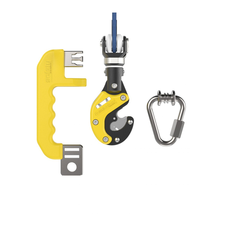
The Self Belay is a safety connector that is used for securing oneself to the end of an auto belay device. It adds to the
safety of climbing through its unique design. The Self Belay Set is comprised of 3 main parts that come packaged
inside the box.
Parts of Self Belay Set:
1: Self Belay body
2: Self Belay key
3: Two delta maillons/links
The abovementioned parts together form the Self Belay Set (1 Self Belay body, 1 Self Belay key and 2 delta maillons/
links).
213
3
THE SELF BELAY SET ALSO COMES WITH THIS MANUAL IN PRINTED FORM INSIDE THE BOX. IT IS
IMPORTANT THAT THE CLIENT KEEP THE ORIGINAL PACKAGING FOR FUTURE REFERENCE/USE.

page 4 www.safetyeng.eu
XXXX/MMYY XXXX – Serial No. in batch
MM – Month of manufacture (e.g. 03 - March)
YY – Year of manufacture (e.g. 17 - 2017)
EN 362:2004/T Complies with EN 362:2004/T
20 kN Major axis breaking load
Read the instructions for use
Complies with European directive CEE/89/686
0158 No. of notied body involved in product conformity checking according Article 11A
Product Identication – looking at the photo below, you can nd the serial number and date of manufacture of the
Self Belay set.
2. Manufacturer’s Details
Safety Engineering Ltd.
Address: Tsarigradsko shose 111V, 1784 Soa, Bulgaria
VAT No: BG175376730
Telephone: +359887825275

page 5 www.safetyeng.eu
3. Specications
Dimensions as installed:
Width: 63 mm Height: 200 mm (including quick link Delta assembly)
Depth: 27 mm Weight as installed: 320 g
Main body
Material: AISI 304, EN AW 7075 Min. breaking strength: 20 kN axial load
Device gate opening: 11 mm This product meets the requirements of EN 362:2004/T.
Quick link Delta assembly
Material: AISI 304 Min. breaking strength: 30 kN axial load
Device Gate opening: 10 mm This product meets requirements of EN 362:2004/Q.
Conformity assessment was done by notied body No. 1019, VVUU a.s., Pikartska 1337/7, 716 07 Ostrava - Radvanice,
Czech Republic
Control according to Article 11A is done by notied body No 0158, DEKRA EXAM GmbH, Dinnendahl
str. 9, D-44809 Bochum, Germany
Dimensions (in millimeters):

page 6 www.safetyeng.eu
4. Compatibility with Autobelays and harnesses
The Self Belay set is compatible with the following auto belay devices:
-Onbelay 8, 11, 14 and 17 manufactured by Safety Engineering Ltd.
-Trublue and Trublue XL manufactured by Head Rush technologies
-*Perfect Descent Direct Drive and Perfect Descent Speed Drive manufactured by C3 Manufacturing LLC (Perfect
Descent)*(see notice below)
The Self Belay set is compatible with harnesses that conform to the following standards:
• EN 361 - Personal protective equipment for prevention of falls from a height – Full body harness.
• EN 813 - Personal protective equipment for prevention of falls from a height – Sit harness.
• EN 12277 - Type A. Full Body Harness.
• EN 12277 - Type B. Small Full Body Harness.
• EN 12277 - Type C Sit Harness.
*NOTICE: The Self Belay body can be retrotted to C3 Manufacturing LLC (Perfect Descent) devices, but Safety
Engineering has no formal contract with the manufacturer. Therefore, the client must contact C3 Manufacturing
LLC (Perfect Descent) before installing the Self Belay device on their belays!
5. Installation and Usage
List of tools:
In order to successfully install self belays on auto belay devices, you will need the following tools:
• A at screwdriver
• Pliers
Installation on steel cable
The installation of the Self Belay on a steel cable includes the following steps:(1) Remove the horseshoe washer with
a at screwdriver from the pin as shown in Photo 2-3. (2) Lift and remove the pin assembly and the plastic washers as
shown in Photos 4-6. (3)Position the cable between the plastic washers as shown in photo 7-9. (4) Reinstall and press
down the pin assembly as shown in Photo 10-12. (5) Reinstall the horseshoe washer and click it to the pin with pliers
as shown in Photo 6. (6) Reinstall and horseshoe washer with pliers as shown in Photos 13-14.
1. Remove the horseshoe washer with a at screwdriver from the pin as shown in Photo 2-3.
1 2 3

page 7 www.safetyeng.eu
2. Lift and remove the pin assembly and the plastic washers as shown in Photos 4-6.
4 5 6
3. Position the cable between the plastic washers as shown in photo 7-9.
7 8 9

page 8 www.safetyeng.eu
4. Reinstall and press down the pin assembly as shown in Photo 10-12.
10 11 12
5. Reinstall and horseshoe washer with pliers as shown in Photos 13-14.
13 14

page 9 www.safetyeng.eu
Installation on textile webbing
The self belay is installed on textile webbings in the following manner. (1) Please refer to steps 2-6 from Installation on
steel cable for the removal of the pin, horseshoe washer and plastic washers. The procedure is the same here. (2) The
webbing is positioned through the loop as shown in Photo 1-3. The pin is reinstalled as shown in photos 4-6. The pin is
pressed down as shown in Photos 5-6. (3) The horseshoe washer is then reinstalled with pliers as shown in Photos 7-8.
1. The webbing is positioned through the loop as shown in Photo 1-3.
1 2 3
2. The pin is reinstalled as shown in photos 4-6. The pin is pressed down as shown in photos 5-6. The plastic washers
are not used when installing the Self Belay on a webbing.
4 5 6

page 10 www.safetyeng.eu
3. The horseshoe washer is then reinstalled with pliers as shown in Photos 7-8.
7 8
USAGE WARNING: ONLY USE THE SELF BELAY AS INSTRUCTED IN THIS MANUAL AND ONLY FOR
ITS INTENDED PURPOSE. IF MALFUNCTION IS SUSPECTED, STOP OPERATING THE DEVICE AND
INSPECT THE UNIT. THE SUPPLIER AND MANUFACTURER ARE NOT LIABLE FOR DAMAGE DUE TO
IMPROPER USE OR DEVICE ALTERATION.
Тhe Self Belay maillon is attached to the harness and then inserted into the Self Belay body as shown
in Photos 1-3 (left to right). The key is then grabbed and pulled outward as shown in photos 4-6 in
order for the body to be released and the user to start climbing. The process is repeated backwards
in order to secure the Self Belay device to the wall.
Note that the Self Belay maillon is held by hand in the photos, while when in operation it is
attached to the harness of the user!
1
4
2
5
3
6

page 11 www.safetyeng.eu
6. Warranty info
• Self Belay body: The Self Belay body is warranted for 12 months, counted from the date of arrival to the client.
Any damage, excluding normal wear and tear or unauthorized tinkering with the device by the client or third parties,
that leads to the device being dysfunctional or unsafe within the 12 month period obliges the manufacturer (Safety
Engineering) to send (a) replacement new or refurbished device/s to the customer at no cost. The replacement device
will be warranted for the remainder of the 12 month period and the additional operational time that the client has lost
while waiting for the replacement device/s..
• Self belay accessories: (Self Belay key and delta maillon/quicklink):
The Self Belay key and delta maillon/quicklink are warranted for 6 months from the date of arrival to the client. Any
damage that leads to the device being dysfunctional or unsafe within the 6 month warranty period obliges the
manufacturer to send (a) replacement new or refurbished device/s to the customer at no cost. The replacement
device will be warranted for the remainder of the 6 month period and the additional operational time that the client
has lost while waiting for the replacement device/s.
Read this carefully!
7. Inspection and Maintenance schedule
Daily inspection:
The Self Belay devices should be carefully inspected daily before the start of each work day in order to ensure their
safety and smooth operation. The following procedures must be followed in order to ensure optimal safety and
eciency:
1. The condition of the swivel must be checked by twisting the upper part as shown in Photo 1 below. It should move
freely in both directions.
1 2

page 12 www.safetyeng.eu
Check for any rust or cracks in the area shown in Photo 1.
In case any rust or cracks are visible, contact Safety Engineering immediately at [email protected] !
2. The plastic covers on both sides should be inspected for cracks and damage as shown in Photo 3 and 4 below.
3. Pay special attention to the middle pin!
In case the middle pin has a width of less than 3,5mm at the base, or if it has cracked/bent or broken retire the key
Refer to Photos 5 and 6 as to how to measure the width of the middle pin. The middle pin must be 4mm wide at the
time of purchase!
3
5
4
6
4 mm pin 3 mm pin

page 13 www.safetyeng.eu
4. The Self Belay key should be inspected in the highlighted area for damage, twisting, bending or breakage as shown
below in Photos 7-9.
5. Make sure that the delta maillon inserts in the discs (shown in Photo 10) easily and without excessive eort. In case
of jamming or unresponsiveness of the discs, try lubricating them with a silicone/oil based lubricant. If the problem
7 8 9
10

page 14 www.safetyeng.eu
6. Make sure the key inserts in and out of the self belay body easily and without excessive eort.
Inspect the lock pins in the Self Belay body as shown in Photo 11. It is normal for the pins to become worn with time,
but there cannot be any breakage! If one or both of the pins have broken, retire the device immediately and contact
7. After purchase and immediately after installation, inspect each self belay device for the presence of the horseshoe
washer (shown below in Photo 12). If absent, retire the device immediately and either contact the manufacturer for
replacements or buy them in a store locally after consulting manufacturer for part name, number etc.
11
12

page 15 www.safetyeng.eu
8. Inspect the pin assembly for cracks, rust or breakage. If any of those are present, as shown in Photo 14, retire the
device immediately.
13 14

page 16 www.safetyeng.eu
Part Check Action
(if answer is YES)
Additional
action
Regularity
of check
Self Belay key
middle pin
Thickness at base
<3,5mm (YES/NO)
Retire the key/s im-
mediately and contact
manufacturer for
replacement key/s.
N/A Daily
Self belay swivel
Cracks or bending
visible (YES/NO)
Retire device imme-
diately and contact
manufacturer for
replacement.
N/A Daily
Does not rotate freely
or jams.
Retire device imme-
diately and contact
manufacturer for
replacement.
N/A Daily
Self belay discs Do not move freely
and/or jam (YES/NO)
Lubricate the discs
with WD40 or equiv-
alent and try locking
the device again. Did it
work? (YES/NO) If NO,
see Additional action.
Retire the device and
contact the manufac-
turer for replacement.
Daily
Self belay pin assem-
bly
Has rust or cracks/
breakage
(YES/NO)
Retire device imme-
diately and contact
manufacturer for
replacement.
N/A
Self belay lock pins One or both have
visible breakage
Retire the device and
contact the manufac-
turer for replacement.
N/A Daily
Self belay delta maillon
Does not fully insert in
the discs of the Self be-
lay body or jams when
inserted. (YES/NO)
Do 5-10 lock-unlock
tests as shown in
part 4. Usage. Inspect
the delta maillon for
defects. Does it work
now?
(YES/NO)
Contact the manufac-
turer for replacement
delta maillon/s. If you
have spare maillons,
use them.
Daily
Self belay plastic covers Have cracks
(YES/NO)
Recommended to
contact manufacturer,
but can continue to
operate as the plastic
covers serve aesthetic
purpose only.
Daily
Self belay
horseshoe washer
Is broken/absent (YES/
NO)
Retire device immedi-
ately. Contact the man-
ufacturer and order
replacement washer/s
or buy replacement
washers from a store.
Consult manufacturer
for part name, number
etc.
Once, immediately af-
ter purchase and once
again immediately
after installation.
DAILY CHECKLIST
Please consult the following checklist for your inspections. Perform each check before the beginning of each working
day:

page 17 www.safetyeng.eu
•Annual Maintenance
You have two options when performing the annual maintenance and servicing of the Self Belay.
• The rst option is to send the devices to the manufacturer for servicing. The steps to be taken are outlined below:
Sending device to manufacturer
1.11 months after the Self Belay/s have been in use, the customer contacts the manufacturer (Safety Engineering) at
2.For a xed price, the manufacturer sends out new or refurbished devices to the client. The client is then required to
send back their old devices to the manufacturer within a week of receiving the replacement ones. This is to ensure
that the old devices are not mistakenly still used after the reception of the replacement devices.
3.The new or refurbished devices are warranted for a further 12 months from the date of arrival to the client.
4.Any damages that make the Self Belay unsafe within the warranty period will be dealt with as dened in point 3.
Warranty info.
• The second option, in case you are willing to do the maintenance yourself, is outlined below.
DIY annual maintenance
Explained below is the procedure for the disassembly, servicing and reassembly of the self belay devices that is done
annually. In case the client is unwilling to send the devices for servicing to the manufacturer, below is the outlined
procedure. It is crucial that the client follows the steps EXACTLY as outlined and uses the same tools or equivalents of
the same type.
WARNING: NOT COMPLETING THE INSPECTION WITHIN THE TIMEFRAME MENTIONED
BELOW COULD RESULT IN SERIOUS INJURY OR DEATH. THE ADVICE BELOW IS TO BE TAKEN
SERIOUSLY AND PRIORITIZED.

page 18 www.safetyeng.eu
Parts of the Self Belay:
Parts that need to be replaced every 12 months:
Component OEM number Quantity
Side cover, right SB.01.00.00.12R 1
Side cover, left SB.01.00.00.12L 1
Locking disc, central SB.01.00.00.03 1

page 19 www.safetyeng.eu
Locking disc, side SB.01.00.00.04 2
Locking anchor, left SB.01.00.03.00L 1
Locking anchor, right SB.01.00.03.00R 1
Positioning spring SB.00.00.07 1
Positioning roller SB.00.00.08 1
Sheet spring SB.01.00.00.14 1
Torsion spring - right SB.01.00.00.015R 1
Torsion spring - left SB.01.00.00.015L 1
Folding spring bolt SW.00.06 3 (2 spare)

page 20 www.safetyeng.eu
Bushing SW.00.03 1
Swivel pin DIN 913 - M8x25 - A2-70 1
Lock washer, E-type DIN 6799-7 A2 3 (2 spare)
Flat round head rivet DIN 674 3x16 - St 5 (1 spare)
Hex socket head cap screw ISO 4762 M4x25 - A2 3
Hex nut ISO 4032 M4 - A2 3
Locking anchor pin ISO 8734 3x10 - A - St 2
Central pin ISO 8734 4x10 - A - St 1
Equipment needed:
• Milling machine
• Vice
• 3mm milling bit
• 3mm Allen key
• Hammer
• Rivet removal tool
• Pocket at screwdriver
• Pneumatic/compressed air gun
Other manuals for SELF BELAY
2
Table of contents
Other Safety Engineering Safety Equipment manuals