Introduction
The 715r Passive Infra Red (PIR) is an indoor detector designed to work with the 9955
and 9960 RFX, the 7500r Domestic Radio Panel, and the 769r and 762r radio receivers.
The PIR detects movement of body heat. The detector has a fan shaped sensitive area
approximately 12 metres in radius. The case is protected by an internal tamper switch.
The back of the case can be modified by removing a cutout to provide a wall tamper.
Specification
Part No. 715rEUR-02
Power Supply 2 x AA alkaline cells
Operating temp: -10 to +55 °C
Low voltage alarm: 2.4V nominal
Lens: Standard 12m x 90 deg.
White light filter: greater than 2000 Lux
RF Immunity: 10V/m
Environmental Class I (Tested -10 to +55°C)
Security Class II
INCERT C0160195
Specification subject to change without notice.
Siting
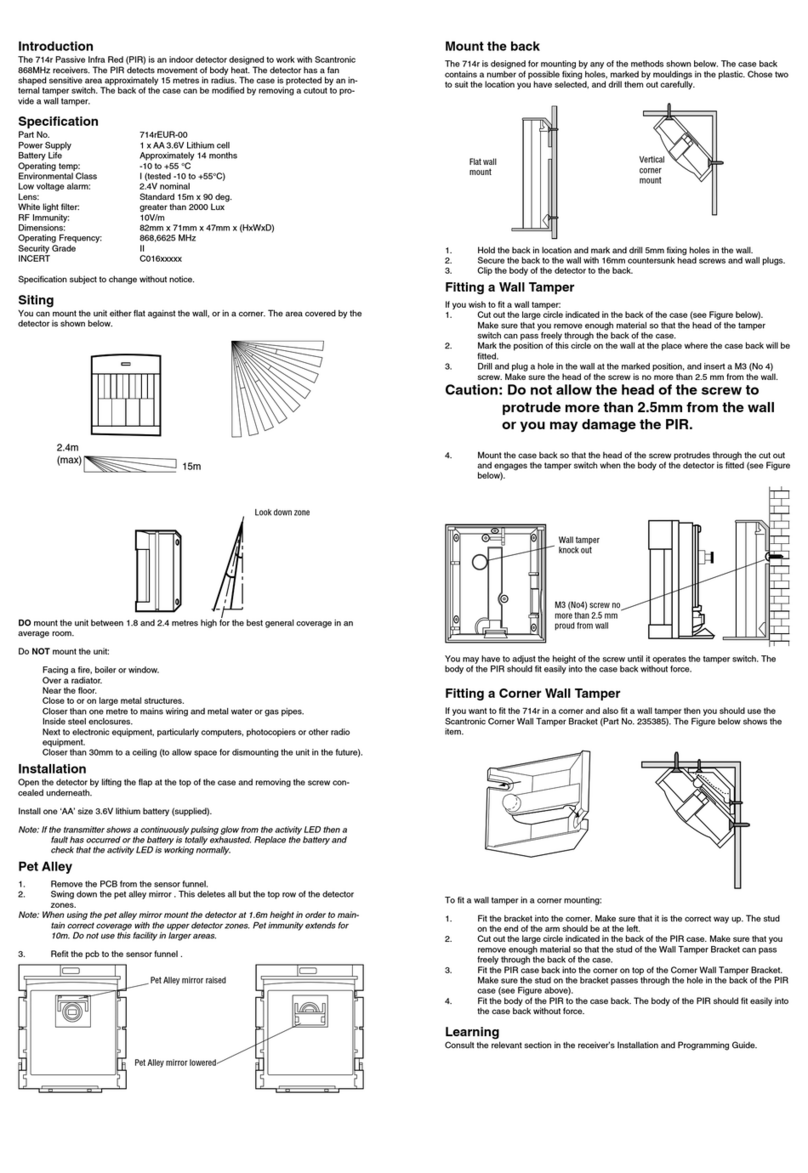
You can mount the unit either flat against the wall, or in a corner. The area covered by the
detector is shown in Figure 4.
2.4m
(max) 12m
DO mount the unit between 1.8 and 2.4 metres high for the best general coverage in an
average room.
Do NOT mount the unit:
Facing a fire, boiler or window.
Over a radiator.
Near the floor.
Close to or on large metal structures.
Closer than one metre to mains wiring and metal water or gas pipes.
Inside steel enclosures.
Next to electronic equipment, particularly computers, photocopiers or other radio
equipment.
Closer than 30mm to a ceiling (to allow space for dismounting the unit in the future).
Installation
Open the detector by lifting the flap at the top of the case and removing the screw con-
cealed underneath.
Install two ‘AA’ size alkaline batteries (not supplied). Do not use rechargeable (Nickel Cad-
mium) batteries, because they are 1.2V and not 1.5V.
Note: If the transmitter shows a continuously pulsing glow from the activity LED then a
fault has occurred or the battery is totally exhausted. Replace the battery and
check that the activity LED is working normally.
Pet Alley
1. Remove the PCB from the sensor funnel.
2. Swing down the pet alley mirror . This deletes all but the top row of the detector
zones.
Note: When using the pet alley mirror mount the detector at 1.6m height in order to main-
tain correct coverage with the upper detector zones. Pet immunity extends for
10m. Do not use this facility in larger areas.
3. Refit the pcb to the sensor funnel .
Mount the back
The 715r is designed for mounting by any of the methods shown below. The case back
contains a number of possible fixing holes, marked by mouldings in the plastic. Chose two
to suit the location you have selected, and drill them out carefully.
1. Hold the back in location and mark and drill 5mm fixing holes in the wall.
2. Secure the back to the wall with 16mm countersunk head screws and wall plugs.
3. Clip the body of the detector to the back.
Fitting a Wall Tamper
If you wish to fit a wall tamper:
1. Cut out the large circle indicated in the back of the case (see Figure 7).
Make sure that you remove enough material so that the head of the tamper
switch can pass freely through the back of the case.
2. Mark the position of this circle on the wall at the place where the case back will be
fitted.
3. Drill and plug a hole in the wall at the marked position, and insert a M3 (No 4)
screw. Make sure the head of the screw is no more than 2.5 mm from the wall.
Caution: Do not allow the head of the screw to
protrude more than 2.5mm from the wall
or you may damage the PIR.
4. Mount the case back so that the head of the screw protrudes through the cut out
and engages the tamper switch when the body of the detector is fitted (see Figure
7).
You may have to adjust the height of the screw until it operates the tamper switch. The
body of the PIR should fit easily into the case back without force.
Fitting a Corner Wall Tamper
If you want to fit the 715r in a corner and also fit a wall tamper then you should use the
Scantronic Corner Wall Tamper Bracket (Part No. 235385). Figure 8 shows the item.
To fit a wall tamper in a corner mounting:
1. Fit the bracket into the corner. Make sure that it is the correct way up. The stud
on the end of the arm should be at the right.
2. Cut out the large circle indicated in the back of the PIR case (see Figure 7). Make
sure that you remove enough material so that the stud of the Wall Tamper
Bracket can pass freely through the back of the case.
3. Fit the PIR case back into the corner on top of the Corner Wall Tamper Bracket.
Make sure the stud on the bracket passes through the hole in the back of the PIR
case (see Figure 8).
4. Fit the body of the PIR to the case back. The body of the PIR should fit easily into
the case back without force.
Learning
See the Installation and Programming Guides for the 9960, 9955, 7500r, 768r and 762r
receivers.
Wall tamper
knock out
M3 (No4) screw no
more than 2.5 mm
proud from wall
Pet Alley
mirror
Vertical
corner
mount
Flat wall
mount
Look down zone


