Cooper Power Tools UTICA PL12-UT02 User manual

Operating Instructions
PL12-UT02 July 27, 2007
Click-Type Torque (Sensing) Wrenches
Cooper Power Tools
P.O. Box 1410
Lexington, SC 29071-1410
For additional product information visit our website at www.cooperpowertools.com
45-8448
OPERATING INSTRUCTIONS FOR MICROMETER
ADJUSTABLE TORQUE SENSING WRENCHES
This Torque Sensing Wrench is designed with the user in
mind. It automatically signals by SOUND and IMPULSE when
your desired torque is reached. This wrench is the result of
many years of research by Cooper Power Tools and if given
proper care should provide many years of satisfactory service.
This wrench is calibrated for both right hand (clockwise) and
left hand (counter clockwise) torque application. The TCI-
600FRN and TCI-7250R are calibrated right hand only.
TO SET AT A TORQUE:
To Unlock: Pull back the automatic Lock Collar and hold in
the rearmost position.
While holding the Lock Collar in this position advance the
Handle up the Barrel by turning it in a clockwise direction. (To
move the Handle down the Barrel turn it in a clockwise
direction.) The Barrel is marked in even increments of torque
and one complete turn of the Handle will advance the torque
one complete barrel increment.
If the Barrel is marked in increments of ten, each complete
turn of the Handle would advance one Barrel increment, i.e.
from 10 to 20. The Sleeve Die is marked around the
circumference with the intermediate increments between the
10 and the 20.
The Sleeve Die markings start at 10 and are evenly divided
into ten marks. Every other mark is numbered. To set at an
even Barrel increment the zero marking on the Sleeve Die
should line up with the down center of the Barrel marking (See
Fig.2) Now by advancing the Handle one Sleeve Die mark you
have increased the torque an amount equal to 1/10th the
increase between two Barrel increments (see Fig. 3).
If the Barrel increments were 10, 20, etc. and the original
setting was 10, by moving the Handle on Sleeve Die
increment you increase the torque an amount equal to 1 and
your total torque would be equal to the Barrel marking plus the
Sleeve Die marking or 10 plus 1 equals 11. If you turned the
Handle four Sleeve Die marks in a clockwise direction from
zero you have advanced the torque 4 increments and your
total torque (if the original setting was 10) would be 10 plus 4
equals 14 (See Fig.4).
TO RELOCK:
When you have lined up a Sleeve Die marking with the line
down the center of the Barrel, you can release the Lock Collar
and it will automatically move forward and lock the Handle to
the Barrel.
TO USE:
Attach the appropriate socket wrench, or adapter to the torque
wrench square drive and apply the wrench to the fastener to
be tightened. Hold the torque wrench by the padded handle at
the end of the wrench and tighten the fastener. As the final
tightening of the faster is approached, apply force with a
steady, smooth action.
Do not apply force by holding any part of the wrench, other
than the padded handle. Do not use an extension or other
lever aid on the handle. When the set torque is reached, the
wrench will momentarily release with a feel impulse and
audible click. The wrench will move freely through a small arc
of approximately two (2) degrees. At this point the set torque
has been achieved and force on the handle must be released.
The wrench will automatically snap back to it’s original
position and be ready for the next torque application.
Note: When set at the lower torque range, the audible signal
will be much lower. However, there is an audible sound which
in conjunction with the feel impulse should present no difficulty
in operating the wrench at low scale settings.

Utica®
Click-Type Torque (Sensing) Wrenches
Page 2
PL12-UT02
July 27, 2007
TORQUE EXTENSIONS
When an extension is used on the drive end of the torque
wrench, the torque applied at the end of the extension is
NOT the same as the torque set on the wrench. The method
of determining the actual torque produced using various
types of extensions is as follows:
Ta= Torque applied at the end of extension
Tw = Torque Wrench setting
L = Length of wrench (Center of handle to drive)
A = Length of extension (always taken parallel to the
line of the wrench regardless of extension
configuration)
NOTE: To obtain the actual torque values as calculated,
force must be applied only at the center point of the handle.
SUGGESTIONS FOR LONGER TOOL LIFE
1. When the Wrench is not in use keep it at the lowest
reading.
2. Always actuate the tool a few times before use after a
period in which the tool has been inactive.
3. If the unit is dropped it should be checked on a Torque
Tester before use .
NOTE: THIS IS A PRECISION INSTRUMENT: It is as precise
as a micrometer and should not be used as a hammer,
chisel,or any other tool.
REPAIR CALIBRATION & CERTIFICATION SERVICE
Cooper Power Tools maintains service repair centers to assure
proper service for it’s products. All standards used in the
calibration of torque products are traceable to the National
Institute of Standards and Technology (NIST).
SETTING THE TCI-75FRN TORQUE WRENCH
The torque settings of the wrench are read from two
micrometer scales: the Major and Fine scales. This wrench
has the capacity to work in English units (foot-pounds)and
International units (Newton meters): therefore, there are two
major and fine scales. The major English scale is located on
one side of the barrel and is divided into increments of 5 Ft.-
Lbs. The major International scale is located on the opposite
side of the barrel and is divided into increments
of 6.8 Nm. The fine micrometer adjustments are
made with the sleeve which has increments of
0.5 Ft.-Lb. on the upper scale and increments of
0.68 Nm (rounded) on the lower scale.
Setting the wrench is accomplished by considering all torque
settings as being made up of two parts, 5 Ft.-Lbs.(6.8 Nm)
increments and 0.5 Ft.-Lbs. (0.68 Nm) increments.
Thus a torque setting of 42 Ft.-Lbs. would be considered as 40 ft.-
Lbs. on the major scale plus 2 Ft.-Lbs. on the fine scale. The wrench
is set to the desired torque as follows
1. Grasp the locking collar between the
thumb and forefinger and pull it toward the
handle of the wrench as far as it will go.
Hold it in this position.
Ratchet Head
Plain Head
Padded Handle
Ratcheting Model
Standard Model
Barrel
Sleeve Die
Lock Collar
Figure 1
Figure 2 Figure 3 Figure 4

Page 3
Utica®
Click-Type Torque (Sensing) Wrenches
PL12-UT02
July 27, 2007
2. While holding the barrel of the wrench securely
in one hand rotate the handle of the wrench
until the major five foot pound increment below
the torque desired is even with the edge of the
sleeve and the 0 increment on the sleeve is in
line with the zero line of the barrel.
3. Rotate the handle clockwise until the fine
torque increment desired lines up with the zero
line on the barrel. Release the lock collar and
the wrench is automatically locked at the
torque setting selected.
NOTE: The lock collar will not lock until an increment line
on the sleeve lines up with the zero line on the barrel.
4. For Newton meter torque settings, use the
same procedure as above using the Newton
meter major scale on the barrel and the lower
set of graduations on the sleeve. The picture at
the right shows a setting of 59.0 Nm. This can
be accomplished by setting 57.6 on the major scale plus 1.4
on the fine scale to equal 59.0 NM. Note that the fine scale
has been rounded to the nearest whole decimal.
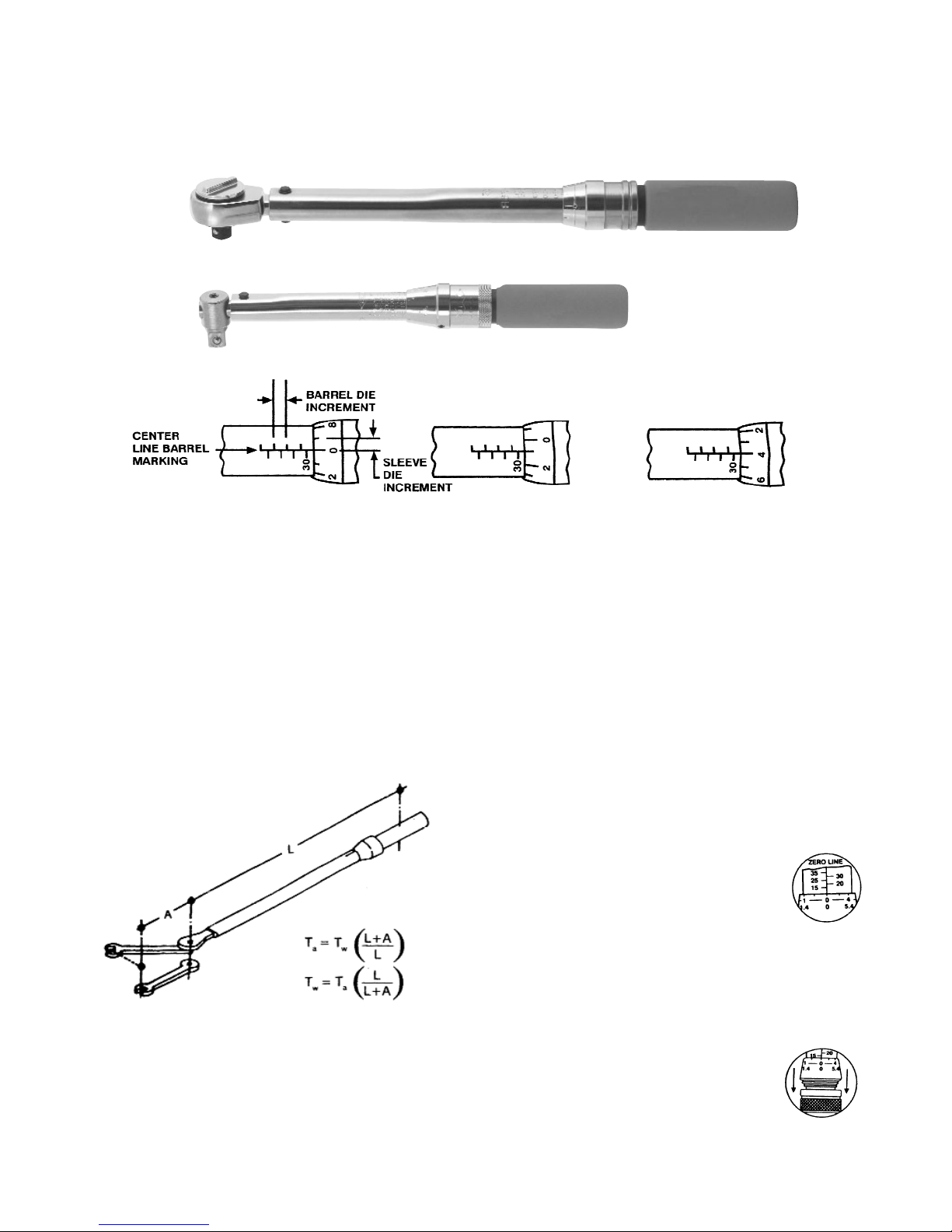
SETTING THE TCI-150FRN & TCI-250FRN TORQUE
WRENCHES
The torque settings of the wrench are from two micrometer
scales: the Major scale and the Fine scale. This wrench has
the dual capacity of working in English units (foot-pounds) and
International units (Newton meters): therefore, there are two
major and fine scales. The major English scale is located on
one side of the barrel and is divided into increments of 10 Ft.-
Lbs. The major International scale is located on the opposite
side of the barrel and is divided into increments of
13.6 Nm. The fine micrometer adjustments are
made with the sleeve which has increments of
one Ft.-Lb. on the upper scale and increments of
1.36 Nm (rounded) on the lower scale.
Setting the wrench is accomplished by considering all torque
settings as being made up of two parts, 10 Ft.-Lbs.(13.6 Nm)
increments and 1 Ft.-Lb. (13.6 Nm) increments. Thus a torque
setting of 65 Ft.-Lbs. would be considered as 60Ft.-Lbs. on the
major scale plus 5 Ft.-Lbs. on the fine scale. The wrench is set
to desired torque as follows:
1. Grasp the Locking Collar between the thumb
and forefinger and pull it toward the handle
of the wrench as far as it will go. Hold it in
this position.
2. While holding the barrel of the wrench
securely in one hand rotate the handle of the
wrench until the major 10 Ft.Lbs. increment
below the torque desired is even with the
edge of the sleeve and the 0 increment on
the sleeve is in line with the zero line of the barrel.
3. Rotate the handle clockwise until the fine torque increment
desired lines up with the zero line on the barrel. Release the
lock collar and the wrench is automatically locked at the torque
setting selected. NOTE: The lock collar will not
lock until an increment line on the sleeve lines
up with the zero line on the barrel.
4. For Newton meter torque settings, repeat the
above procedure using the Newton Meter major
scale on the barrel and the lower set of
graduations on the sleeve. The picture at the
right shows a setting of 79.9 Nm. This is done
by setting 74.5 on the major scale plus 5.4 on
the fine scale to equal 79.9 Nm. Note: fine scale is rounded to
the nearest whole decimal.
“PRE-SET” SENSING TYPE TORQUE WRENCHES
This type torque wrench is designed so when torque is applied to
a fastener, it will momentarily release and signal by feel impulse
and audible click (or snap) that the preset torque value has been
reached.
This preset torque wrench is calibrated and sealed at the factory to
the torque value specified on the customer’s purchase order.
Wrenches are also available not preset or sealed when requested
by the customer. Wrenches preset at the factory are set to an
accuracy tolerance of ±4%of the specified torque value.
TO USE:
1. Attach the proper socket or adapter to the arm or square
drive (A).
2. Attach the wrench to the fastener and apply force to the
torque wrench by grasping the padded handle portion (H) at
the end of the wrench.
CAUTION: Do not apply force by holding any part of the wrench,
other than the padded handle. Do not use an extension or other
lever aid on the wrench. Apply force with a steady, smooth
action. When the set torque is reached, the wrench will
momentarily release with a feel impulse and audible click, or
snap. The wrench will move through a small arc about the pivot
pin (B). At this point the set torque has been achieved and force
on the handle (H) must be released. The wrench will snap back
automatically to it’s original position and be ready for the next
torque application.
3. Caution: Don’t apply force after the wrench releases, (clicks,
or snaps) at the set torque. If the fastener is over torqued,
loosen it and repeat the operation.
4. Always actuate the the wrench a few times before use and
after a period when the wrench has not been in use.

Cooper Power Tools
P.O. Box 1410
Lexington, SC 29071-1410
USA
Toll Free: 800-845-5629
Fax: 803-359-0822
www.cooperpowertools.com
Printed In USA
Utica®
Click-Type Torque (Sensing) Wrenches
PL12-UT02
July 27, 2007
5. THIS UNIT IS A PRECISION INSTRUMENT: It is as precise
as a micrometer and should not be used as a hammer,
chisel, or any other tool. If the unit is dropped it should be
checked on a Torque Tester before use.
TO CALIBRATE OR RE-CALIBRATE:
1. Calibration or re-calibration of this torque wrench should be
done only on a certified Torque Tester for the required
range.
2. With a suitable adapter attach the wrench to the torque
tester.
3. Loosen Lock Plug (F) with a hex key.
4. With a hex key or screwdriver turn the adjusting plug (J) In
a clockwise direction to increase pressure on the torque
spring (G) which increases the torque value. Turn in a
counter- clockwise direction to decrease torque value. Turn
the adjusting plug (J) by small adjustments at a time.
Actuate the wrench by applying force on the padded
handle (H) and observe the readings on the Torque
Tester Scale. Continue adjusting and actuating the
wrench until the desires torque setting has been reached.
5. Tighten the lock plug (F) and check the torque reading
on the Torque Tester.
6. If a seal is desired sure the seal washer (W) is in place
before any liquid seal material is applied.
NOTE: Wrenches calibrated or set at the factory are sealed
with low temperature fusible alloy that can be removed in
boiling water or with a soldering iron.
Table of contents
Other Cooper Power Tools Power Tools manuals