Cooper Tools Quackenbush 180SC-225 Installation and operating instructions

1
Operation & Service Manual
823225 2/01
180SC-225 SELF COLLETING DRILL
Houston Operation
7007 Pinemont
Houston, TX 77040
Recoules Operation
Zone industrielle - B.P. 28
Avenue Maurice Chevalier
77831 Ozoir-la-Ferriere Cedex France

2

3
•Before the tool isconnectedto the airsupply,the throttle should
bechecked forproperoperation (i.e.,throttlevalve moves freely
and returns to closed position).
• Before removing a tool from service or changing drill bits, make
suretheairlineisshutoffanddrainedofair.Thiswillpreventthe
tool from operating if the throttle is accidently engaged.
•Cuttingtoolsusedwiththesedrillmotorsaresharp.Handlethem
carefully to avoid injury.
• The collet and mandrel must be inserted into a properly sized
pre-drilled hole before starting the tool. An improperly sized pre-
drilled hole prevents the mandrel from engaging the collet and
could result in slippage of the tool. An improperly selected collet
and mandrel can also result in slippage of the tool.
Drilling or other use of this tool may produce hazardous fumes
and/or dust. To avoid adverse health effects utilize adequate
ventilation and/or a respirator. Read the material safety data
sheet of any cutting fluids or materials involved in the drilling
process.
Some non-ferrous metal chips (or dusts) are combustible. Ex-
amples: Aluminum, magnesium, Titanium, and Zirconium. See
the material safety data sheets for combustibility of materials
drilled. Never collect spark generating material with combustible
material. Examples: Collecting both steel and aluminum or steel
and titanium.
Quackenbush drills are often used with lubricant or cooling
systems which must be properly maintained to avoid leakage.
Failure to do so can result in serious injuries from slipping on oily
surfaces.
Foryour safety and the safety of others, read and understand
the safety recommendations and operating instructions be-
fore operating any drill motor.
Always wear protective equipment:
Foradditionalinformationoneyeprotection,readthelatestedition
of ANSI Z87.1, Occupational and Educational Eye and Face
Protection. This standard is available from the American National
Standards Institute, Inc., 11 West 42nd Street, New York, N.Y.
10036.
Hearing protection is recommended in high noise areas (above
85dBA). Close proximity of additional tools, reflective surfaces,
process noises, etc., can contribute substantially to the sound
level experienced by the operator.
Follow good machine shop practices. Rotating shafts and moving
components entangle and entrap, and may result in serious
injuries. Never wear long hair, loose-fitting clothes, gloves, ties,
or jewelry when working with or near a drill of any type.
Quackenbush drills are designed to operate on 90psig (6.2 bar)
maximum air pressure using the proper hose. Excessive air
pressureincreases the loadsand stresseson toolparts anddrills,
and may result in breakage. The installation of a filter-regulator-
lubricator in the air supply line ahead of the tool is highly recom-
mended.
Safety Recommendations
!
Do not wear loose fitting clothes,
long hair, gloves, ties or jewelry.
WARNING
CAUTION!
Personal hearing protection is
recommended when operating
or working near this tool.
WARNING!
Impact resistant eye protection
must be worn while operating
or working near this tool.
CAUTION!
WARNING
!
Wear respirator where
necessary.
CAUTION!
CAUTION!
Slip and fall hazard.
Lubricant and coolant systems must
be properly maintained to avoid
leakage.
Hoses must be organized and care
taken to avoid tripping.

4
Due to the number and variety of tooling applications, the user's
methods engineering departments, ect., must consider any haz-
ards that may be associated with each specific application of this
product and provide adequate operator protection from inadvert-
ent contact with any moving components. The clamping and feed
mechanisms of self-colleting drill motors are exposed for visibility
and can move when the air supply is connected or disconnected.
To avoid injury, keep fingers and hands away from these areas
when handling or operating this tool.
Some individuals are susceptible to disorders of the hands and
arms when exposed to vibration and/or tasks which involve
repetitive work motions. Those individuals predisposed to vascu-
latory or circulatory problems may be particularly susceptible.
Cumulativetraumadisorderssuchascarpaltunnelsyndromeand
tendinitis can be caused or aggravated by repetitious, forceful
exertionsof thehands andarms. These disordersdevelop gradu-
ally over periods of weeks, months, and years. Tasks should be
performed in such a manner that the wrists are maintained in a
neutralposition,whichisnotflexed,hyperextended,orturnedside
to side. Stressful postures should be avoided and can be con-
trolled through tool selection and work location.
Safety Recommendations
Any tool operator should be aware of the following warning signs
and symptoms so that a problem can be addressed before it
becomes a debilitating injury. Any user suffering from prolonged
symptoms of tingling, numbness, blanching of fingers, clumsi-
ness or weakened grip, inability to hold objects, nocturnal pain in
the hand, or any other disorder of the shoulders, arms, wrists, or
fingersshould notifytheiremployer sothat areview of whatsteps
might be taken to prevent further occurances. These steps might
include but are not limited to, repositioning the workpiece or
redesigning the workstation, reassigning tool users to other jobs,
rotating jobs, changing worker pace, and/or changing the type of
tool used so as to minimize stress on the operator. Some tasks
may require more than one type of tool to obtain the optimum
operator/ tool/ task relationship.
The following recommendations will help reduce or moderate the
effectsofrepetitiveworkmotions.Theoperatorofanydrillshould:
• Use a minimum hand grip force consistent with
proper control and safe operation
• Keep body and hands warm and dry
• Avoid anything that inhibits blood circulation
— Smoking Tobacco
— Cold Temperatures
— Certain Drugs
• Avoid awkward postures
• Keep wrists as straight as possible
• Interrupt work, activities, or rotate jobs to provide
periods free from repetitive work motions.
WARNING!
Repetitive work motions can
injure your hands and arms.
WARNING!
Exposure to vibration can
injure your hands and arms.
Extension Neutral Flexion Radial Deviation Neutral Ulnar Deviation
Avoid Avoid Avoid
OK Avoid OK
WARNING
!
Keep hands away from
clamping and feed
mechanisms. Clamp
mechanism moves when
drilling and connecting
or removing air supply.

5
Safety Recommendations
CAUTION
!
Read operating
instructions before
operating tool.
OPERATING
INSTRUCTIONS
203245
- Wear impact resistant eye protection.
- Hearing protection is recommended.
- Avoid contact with rotating spindle or cutter.
- Wear respirator as necessary.
- Exposure to repetitive work motion
and/or vibration may be harmful
to your hands and arms.
WARNING
!
203246
WARNING
!
Keep hands away
from clamping and
feed mechanisms.
Clamp mechanism
moves when drilling
and connecting or
removing air supply.
624242
WARNING
!
Keep hands away from this area when handling
or operating tool. Clamp mechanism moves when
drilling and connecting or removing air supply.
202902
202902
2
03245
203246
624242
Safety Labels
The safety labels found on this tool are an
essentialpartofthisproduct.Labelsshouldnot
be removed. Labels should be checked peri-
odically for legibility. Replace safety labels
when missing or when the information can no
longer be read. Replacement labels can be
ordered by the part numbers shown on this
page.

6
Tool Adjustments
Drill Assembly
Gear Set Assemblies
Accessories
Template Boss
Jig Collet Foot Attachments
High Curvature Pad Assembly
Booster Pump Assembly
Mist Lubricators
Trouble Shooting & Maintenance Kit
3-5
6
7
8-11
12
12-13
13-14
15
15-16
16-18
19
19
20
21
22
23
24
25
26-30
31-32
33
33
33
34-35
34-38
39
Safety Recommendations
Major Tool Components
Introduction and General Information
Air System Diagrams
Backhead Disassembly
Air Motor Disassembly
Spindle Adjustment
Quill & Pressure Foot Removal
How to Change Quills
Feed Clamp Disassembly
Dwell Valve Disassembly
Disassembly of Feed Control Plug
Unclamp Check Valve Disassembly
Retract and Dwell Valve Disassembly
Hydraulic Fluid Reservoir Disassembly
Trigger Disassembly
Pilot Valve Disassembly
Index
Major Tool Components
Special Tools
Collet Guide
Template Boss
(See Accessories)
Accessory Air
Port (250-18 NPT)
Adjustable Tail
Pad
Variable Spacing
Pressure Foot
Bypass Cover Feed Rate
Adjustment
Backhead
Spindle
Adjustment
Clamp
Air Inlet Bushing
(3/8-18 FNPT)
Motor
Exhaust
Feed Sleeve
Spindle
Adjustment
Dwell
Adjustment Depth Control
Nut
Depth Control
Clamp
Trigger
Trigger Lock
Pressure Foot
Nut Tool (623014)
Trigger Lock Tool
(623015)

7
The180SC-225 isair operated,hydraulically controlled tool
thatautomaticallyclamps tothe material, drillsand counter-
sinks close tolerance holes in one operation. The 180S will
produce high quality holes in aluminum, steel, titanium and
petroleum hybrid materials primarily found in the aircraft/
aerospaceindustries.The180Sself-colletingdrillmotorhas
been designed using state-of-the-art technology that pro-
vides maximum power,minimum weight and the highest
degreeofaccuracyfordemandingholepreparationrequire-
ments.
Technical Data
Feed Stroke: Feed stroke of the 180SC-225 is 2.25 inches
to drill and countersink in 2 inch stacked material. The feed
stroke is unaffected by the collet stroke.
Collet Stroke: The 180SC-225 will clamp throughout its
.875 inch stroke. Feed stroke is unaffected by collet stroke.
Spindle Adjustment: The spindle adjustment of .375 inch
allows for drill length variations. See Spindle Adjustment
information on page 25.
Countersink Depth Control: A micrometer adjustment
provides for countersink stop repeatability within .001 inch.
Cutter Sizes: The 180SC-225 will accommodate .500 di-
ameter drills and.875 countersink diameter.
FeedRate:Anadjustabledrillfeedratemechanismenables
the 180SC-225 to drill from 5 seconds per inch to 1 minute
perinch.SeeFeedRateAdjustmentinformationonpage25.
Cutter to Collet Spacing: The cutter to collet distance is
adjustable between 1.00 inch minimum to 3.50 inch maxi-
mum.
Coolant:The180SC-225hasadrillpointcoolantportinthe
pressure foot. A coolant mist lubricator is available (See
Accessories Page 32-38)
Air Motor: The air motor for the 180SC-225 is rated at 1.8
horsepower nominal when supplied with air at 90 p.s.i.
AirConsumption:Airconsumptionofthe180SC-225is68
c.f.m. at 90 p.s.i. dynamic.
Weight:180SC-225weightwiththealuminumpressurefoot
is 14.9 pounds.
Spindle Speeds: Eleven geared spindle speeds are avail-
able with the 180S: 240, 420, 650, 850,1050, 2000, 3100,
4900, 6300, 12500 and 21000 RPM. See pages 31 and 32
for gear set assembly configurations.
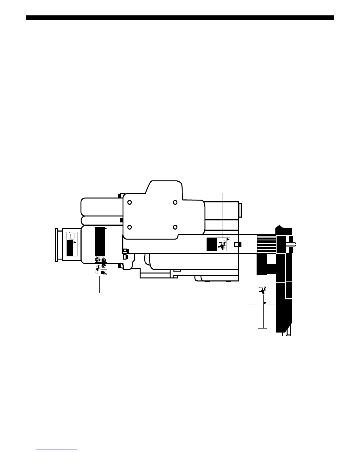
TriggerLock:Atriggerlockisprovidedwhichallowsthetool
to be locked in the "Operate" position. With the lock acti-
vated, the tool will run through the clamp, feed and retract
cycles, but it will not unclamp or stop the motor until the
trigger lock is manually released.
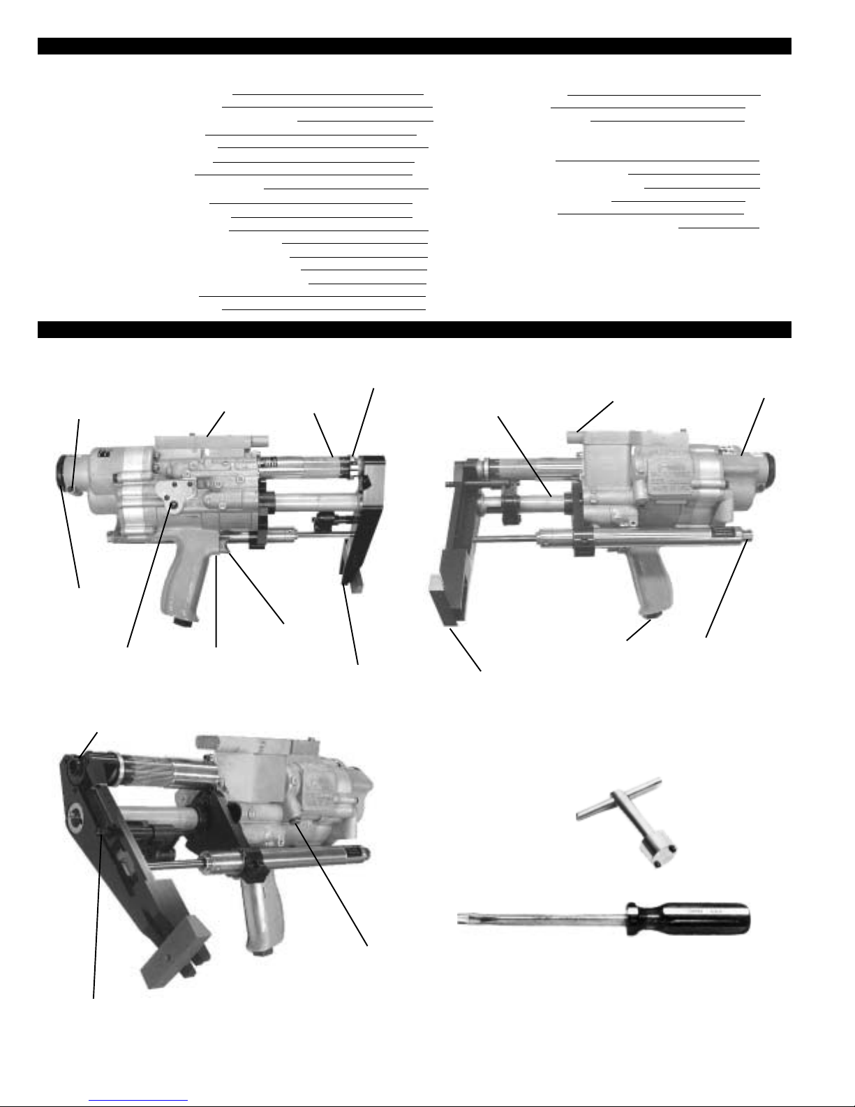
Tool Start-Up
The180SC-225 drill isshipped from the factory equipped to
the customer's specifications: spindle RPM, spindle to ac-
commodate cutter type desired, pressure foot type, collet
guide to accommodate collet desired and optional booster
pump (if required).
After unpacking, examine the customer-specified equip-
ment on the 180SC-225 tool to verify type and speed of
components. Attach air line to 3/8-18 NPT inlet bushing. If
quick disconnect fittings are used, 3/8 in. ID are minimum.
The 180SC-225 drill requires a supply of clean 90-100 PSI
air. Air consumption is 45 CFM at 90 PSI. The use of the in-
line lubricator will provide the proper lubrication for the air
motorand willsignificantly increasethe tool life expectancy.
Because O-rings are extensively used to seal systems
within the tool, the elimination of foreign particles and other
contaminants will reduce the possibility of damage to these
parts. Always inspect O-rings for damage or wear and
replace as required. The use of silicone O-ring lubricant is
strongly recommended during reassembly. The addition of
oilintheairlinewillalsoincreasemotorandvalvelifeaswell
asthelifeoftheO-rings.Avoidtheuseofsyntheticlubricants
to prevent damage to O-rings and seals.
Introduction and General Information
WEIGHT
AIR CONSUMPTION
HORSE POWER
O/A LENGTH
STROKE
COLLET STROKE
COUNTERSINK
FEED RATE
SPINDLESPEEDS
DRILLING THRUST
CLAMPFORCE
SPINDLEADJUSTMENT
MAX. DRILL SIZES
COLLET FOOT SPACING
SPINDLE
COOLANT
180SC-225-14.0 LBS. MAX. W/ALUMINUM FOOT
68 C.F.M. @ 90 P.S.I. DYNAMIC
APPROX. 180S-1.4 @ 90 P.S.I.
180S-15.28 IN. MAX AT FULL EXTENSION
2.225 IN. (DRILL & C/SINK 2 IN. STACK)
.875 IN. (NO LOSS OF FEED STROKE)
COUNTERSINK STOP REPEATS WITHIN .001 IN.
MIN. 5 SEC. PER INCH, MAX 1 MIN. PER INCH
240, 420, 650, 850, 1050, 2000, 3100,
4900,6300,12500,21000
300 LBS. MAX. (WITHOUT BOOSTER PUMP)
548 LBS. START CLAMP STROKE (UNREGULATED AIR)
460 LBS. FULL CLAMP STROKE (UNREGULATED AIR)
.375 IN. ADJUSTMENT TO ALLOW FOR DRILL LENGTH
VARIATIONS
.500DRILL/.875C/SINK
1.00 IN. MIN. - 3.50 IN. MAX.
.500 IN. DIA. W1/4-28 & 3/8-16 O.D. THD OR 1/4-28 I.D. THD
THREAD TYPE DRILLS OR 1/4-28 TAPER-LOK TYPE DRILLS.
AIR BLAST PORT & DRILL POINT PORT IN TEMPLATE STD.,
COOLANT MIST LUBRICATOR AVAILABLE.
180SC-225 DRILL SPECIFICIATIONS

8

9

10

11

12

13

14

15

16

17

18

19

20
Table of contents
Other Cooper Tools Drill manuals

Cooper Tools
Cooper Tools Quackenbush 15QDA-RAB-SU-RS Installation and operating instructions

Cooper Tools
Cooper Tools Quackenbush 15QDA-RA/5RNAL Installation and operating instructions

Cooper Tools
Cooper Tools Quackenbush 140QGDA-RA-SU-MS Installation and operating instructions

Cooper Tools
Cooper Tools Quackenbush 120SC-112 Installation and operating instructions

Cooper Tools
Cooper Tools Cleco Installation and operating instructions

Cooper Tools
Cooper Tools CLECO 111-B Series Installation and operating instructions

Cooper Tools
Cooper Tools Quackenbush 158QGDA-RAD-SU-RS Installation and operating instructions

Cooper Tools
Cooper Tools Quackenbush 15QGDA Installation and operating instructions