manuals.online logo
Brands
  1. Home
  2. •
  3. Brands
  4. •
  5. Copley Controls
  6. •
  7. Servo Drive
  8. •
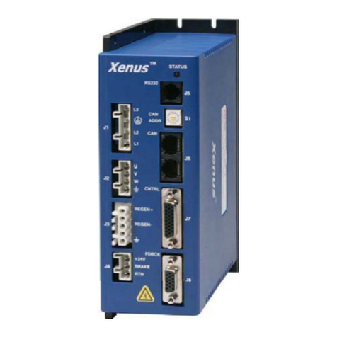
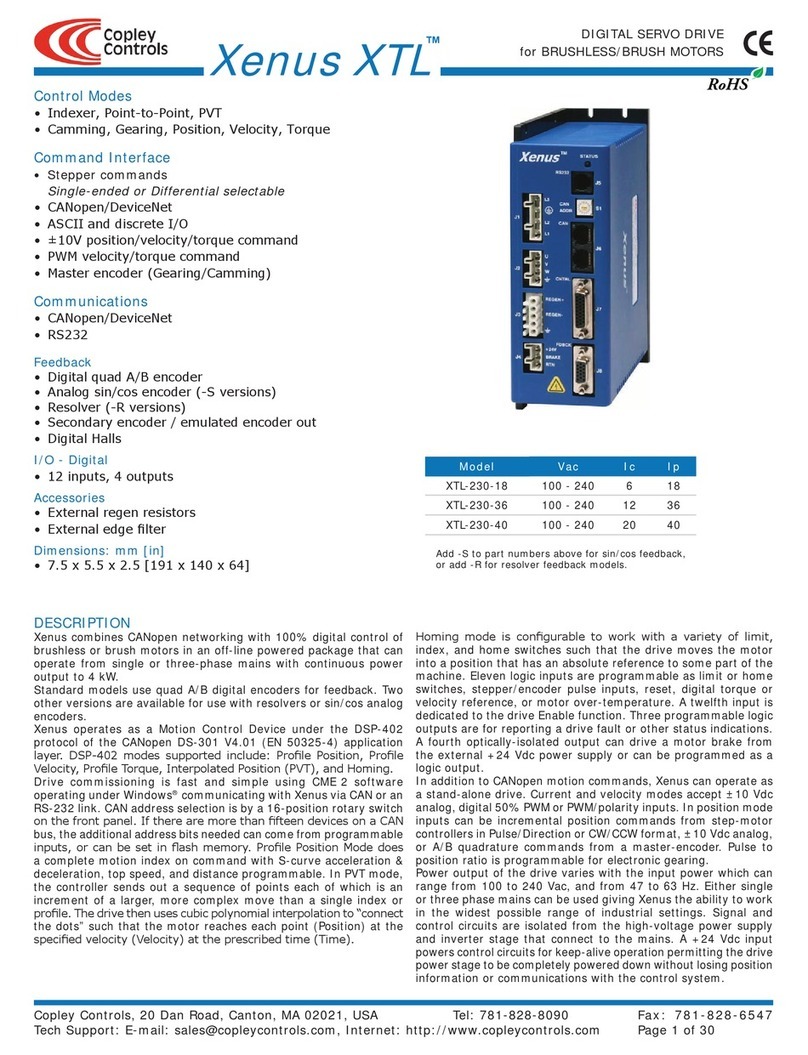
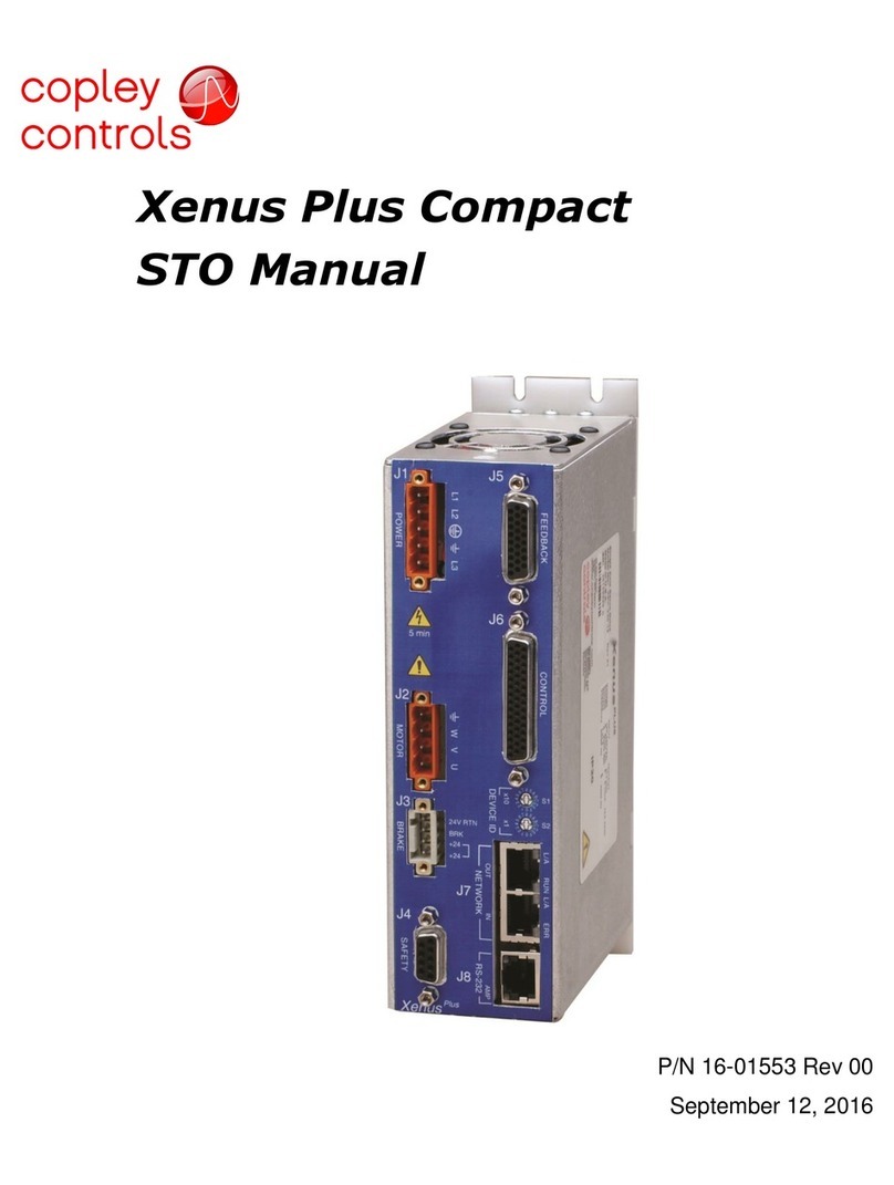
  9. Copley Controls Xenus PLUS User manual

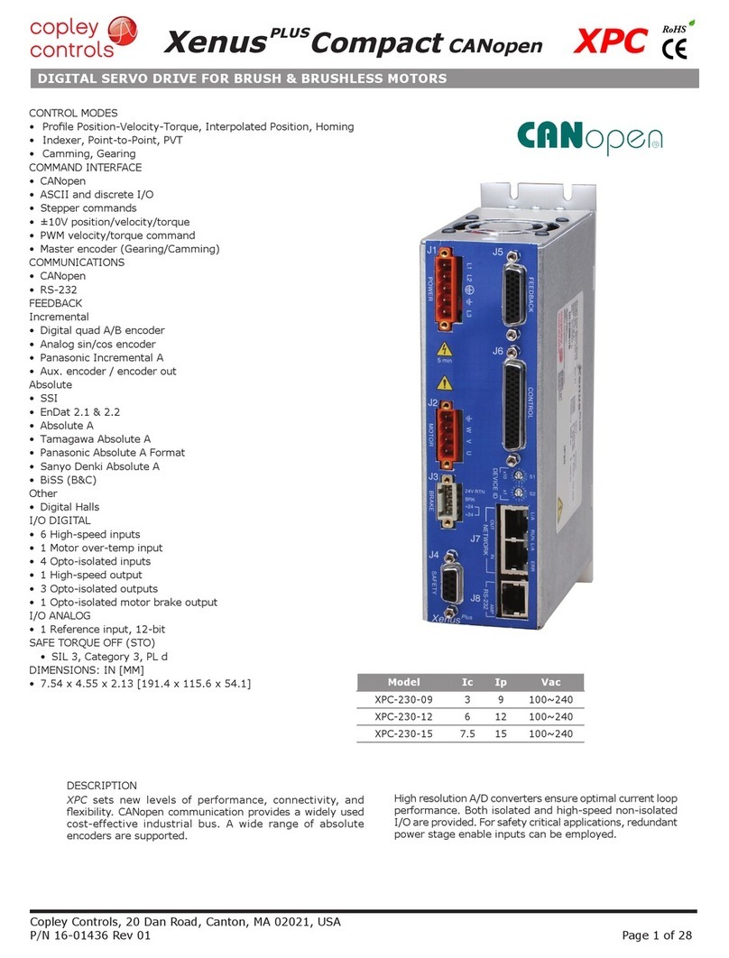
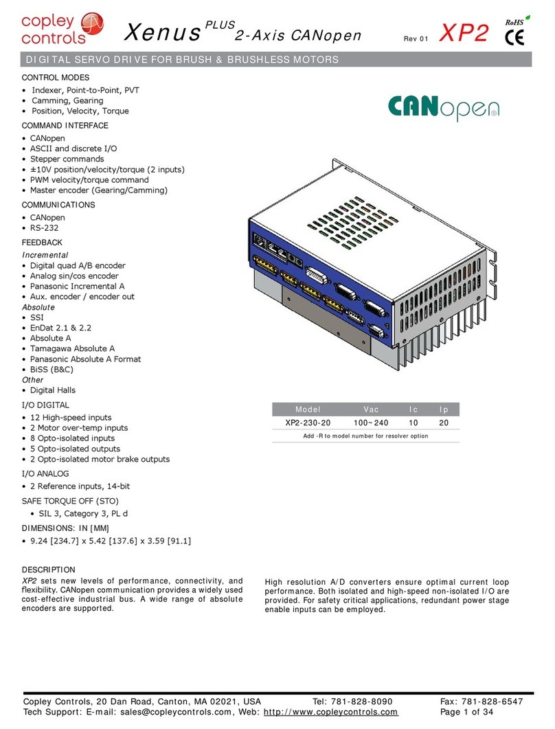
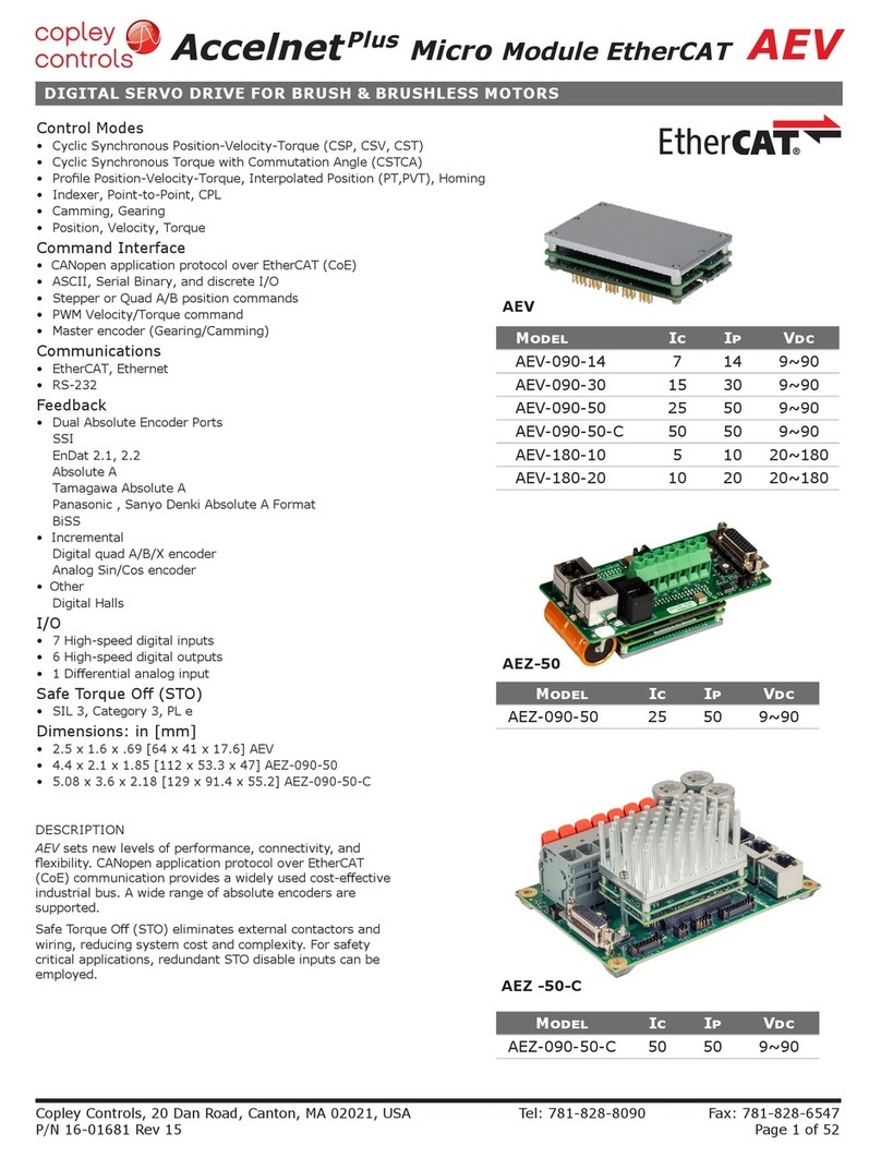
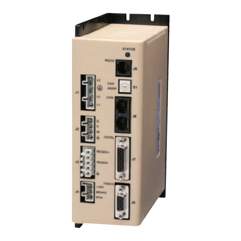
Copley Controls Xenus PLUS User manual

Model Vac Ic Ip
800-1782 100~240 10 20
Copley Controls, 20 Dan Road, Canton, MA 02021, USA Tel: 781-828-8090 Fax: 781-828-6547
Tech Support: E-mail: [email protected], Web: http://www.copleycontrols.com Page 1 of 32
RoHS
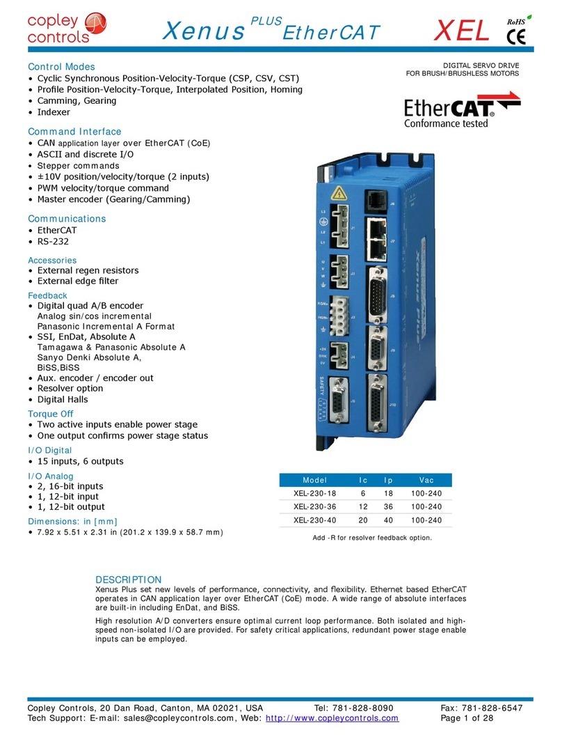
Xenus PLUS 2-Axis EtherCAT
800-1782
Current ratings are for each axis
Control Modes
• CyclicSynchronousPosition-Velocity-Torque(CSP,CSV,CST)
• ProlePosition-Velocity-Torque,InterpolatedPosition,Homing
• Camming,Gearing
• Indexer
CommandInterface
• CANapplication layeroverEtherCAT(CoE)
• ASCIIanddiscreteI/O
• Stepper commands
• ±10Vposition/velocity/torque
• PWMvelocity/torquecommand
• Masterencoder(Gearing/Camming)
Communications
• EtherCAT
• RS-232
Accessories
• Externalregenresistor
Feedback
• NSKSSBMotorIncrementalResolver
• NSKJSGMotorIncremental/AbsoluteResolver
SafeTorqueOff(STO)
• SIL3,Category3,PLd
I/ODigital
• 20inputs,5outputs
• [IN16~19]dedicatedtoNSKrobotlimitswitches
I/OAnalog
• 2inputs,±10V,14-bit
Dimensions:in[mm]
• 9.24[234.7]x5.77[146.6]x2.31[58.7]
2-AXISDIGITALSERVODRIVE
FORBRUSHLESS/BRUSHMOTORS
DESCRIPTION
800-1782setnewlevelsofperformance,connectivity,andexibility.CANapplicationlayeroverEtherCAT
(CoE) communication provides a widely used cost-effective industrial bus. Primary position feedback on both
axessupportsNSKSSBmotors withincrementalVR (variable-reluctance)resolversorNSKJSG motorswith
incremental/absoluteVRresolvers.
HighresolutionA/Dconvertersensureoptimalcurrentloopperformance.Bothisolatedandhigh-speednon-isolated
I/Oareprovided.Forsafetycriticalapplications,redundantpowerstageenableinputs(STO)canbeemployed.
Copley Controls, 20 Dan Road, Canton, MA 02021, USA Tel: 781-828-8090 Fax: 781-828-6547
Tech Support: E-mail: [email protected], Web: http://www.copleycontrols.com Page 2 of 32
RoHS
Xenus PLUS 2-Axis EtherCAT
800-1782
GENERALSPECIFICATIONS
 Testconditions:Wyeconnectedload:2mHline-line.Ambienttemperature=25°C.Powerinput=230Vac,60Hz,1Ø
MODEL 800-1782
OUTPUTCURRENT(EACHAXIS)
 PeakCurrent  20(14)  Adc(Arms,sinusoidal)
Peak time 1s
 Continuouscurrent(Heatsinkrequired)  10(7)  Adc(Arms,sinusoidal)
INPUTPOWER
 Mainsvoltage,phase,frequency 100~240 Vac,±10%,1Øor3Ø,47~63Hz
 MaximumMainsCurrent,1Ø(Note2,page3) 20 Arms
 MaximumMainscurrent,3Ø(Note2,page3) 15.4 Arms
 +24VdcControlpower +20to+32Vdc,0.5~1.1Adc(Note3,page3) Requiredforoperation
DIGITALCONTROL
 DigitalControlLoops Current,velocity,position.100%digitalloopcontrol
Sampling rate(time) Currentloop:16kHz(62.5µs),Velocity&positionloops:4kHz(250µs)
 Busvoltagecompensation Changesinbusormainsvoltagedonotaffectbandwidth
Minimum load inductance 200µHline-line
COMMANDINPUTS(NOTE:DIGITALINPUTFUNCTIONSAREPROGRAMMABLE)
Distributed Control Modes
 CAN application layer overEtherCAT(CoE) CyclicSynchronousPosition-Velocity-Torque,ProlePosition-Velocity-Torque,
 InterpolatedPosition,Homing
Stand-alone mode
 Analogtorque,velocity,positionreference ±10Vdc,14bitresolution Dedicateddifferentialanaloginput
 Digitalpositionreference Pulse/Direction,CW/CCW Steppercommands(2MHzmaximumrate)
 QuadA/BEncoder 2Mline/sec,8Mcount/sec(afterquadrature)
 Digitaltorque&velocityreference PWM,Polarity PWM=0%-100%,Polarity=1/0
 PWM50% PWM=50%±50%,nopolaritysignalrequired
 PWMfrequencyrange 1kHzminimum,100kHzmaximum
PWM minimum pulse width 220 ns
 Indexing Upto32sequencescanbelaunchedfrominputsorASCIIcommands.
 Camming Upto10CAMtablescanbestoredinashmemory
 ASCII RS-232,DTE,9600~115,200Baud,3-wire,RJ-12connector
DIGITALINPUTS
 Number 20
 [IN1,11] Digital,Schmitttrigger,1µsRClter,24Vdccompatible,programmablepull-up/downto+5Vdc/ground,
 Vt+=2.5~3.5Vdc,VT-=1.3~2.2Vdc,VH=0.7~1.5Vdc
 [IN2~5,12~15] Programmableassingle-endedordifferentialpairs,100nsRClter,5Vdcmax,
10 kΩprogrammablepull-up/downperinputto+5Vdc/ground,
 SE:Vin-LO≤2.3Vdc,Vin-HI≥2.7Vdc,VH=45mVtyp,DIFF:Vin-LO≤200mVdc,Vin-HI≥200mVdc,VH=45mVtyp,
 [IN6~9] Opto-isolated,single-ended,±15~30Vdccompatible,bi-polar,groupof4withcommonreturn
 Ratedimpulse≥800V, Vin-LO≤6.0Vdc,Vin-HI≥10.0Vdc,Inputcurrent±3.6mA@±24Vdc,typical
 [IN16~19] DedicatedfunctionforNSKmotorlimitswitches.Internal6Vpowerwithcurrent-limitingresistors.
 [IN10,20] Motorovertempsignalsonfeedbackconnectors,Schmitttrigger,24Vdccompatible,
 330µsRClter,4.99kpullupto+5Vdc,Vt+=2.5~3.5Vdc,VT-=1.3~2.2Vdc,VH=0.7~1.5Vdc
SAFETORQUEOFF(STO)INPUTS
 Function PWMoutputsinactiveandcurrenttothemotorwillnotbepossiblewhentheSTOfunctionisactivated
 Standard ConformancetoIEC61508-1,IEC61508-2,IEC61800-5-2,ISO13849-1
 SafetyIntegrityLevel SIL3,Category3,PerformanceLeveld
 Inputs 2two-terminal:STO_IN1+,STO_IN1-,STO_IN2+,STO_IN2-
 Type Opto-isolators,24Vcompatible,Vin-LO≤6.0Vdcoropen,Vin-HI≥15.0Vdc,
 Inputcurrent(typical) STO_IN1:11.2mA,STO_IN2:11.2mA
 Responsetime 2ms(IN1,IN2)fromVin≤6.0Vdctointerruptionofenergysuppliedtomotor
Reference CompleteinformationandspecicationsareintheXenusPlusDual-AxisSTOManual
ANALOGINPUTS
 Number 2
 [AIN1~2] Differential,±10Vdc,5kΩinput impedance, 14-bit resolution
DIGITALOUTPUTS
 Number 5
 [OUT1~3] Opto-isolatedsolid-staterelays,60mAdcmax,24Vdctolerant,Ratedimpulse≥800V, series20ohmresistor
 MOSFETchannelconnectsthe(±)outputs,Rds-On=10Ωmax@60mAdc,maxVout=32Vdc
 Td-ON=5000µsmax@60mA,Td-OFF=5000µsmax@60mA,timesincluderise/falltimes
 [OUT6~7] Motorbrakecontrol:opto-isolated,current-sinkingwithybackdiodeto+24Vdc(J5-4~5),1Adcmax,Ratedimpulse≥800V
 Td-ON=250µsmax@20mA,Td-OFF=250µsmax@200mA,timesincluderise/falltimes,
Programmable for other functions if not used for brake
RS-232PORT
 Signals RxD,TxD,Gndin6-position,4-contactRJ-12stylemodularconnector,non-isolated,commontoSignalGround
Mode Full-duplex, DTE serial communication port for drive setup and control, 9,600 to 115,200 baud
 Protocol BinaryandASCIIformats
ETHERCATPORTS
 Format DualRJ-45receptacles,100BASE-TX
 Protocol EtherCAT,CANapplicationlayeroverEtherCAT(CoE)
STATUSINDICATORS
 AMP BicolorLED,drivestateindicatedbycolor,andblinkingornon-blinkingcondition
 RUN GreenLED,statusofEtherCATstate-machine(ESM)
 ERR RedLED,showserrorsduetotime-outs,unsolicitedstatechanges,orlocalerrors
 L/A GreenLED,Link/Act,showsthestateofthephysicallinkandactivityonthelink(EtherCATconnection)
 RUN,ERR,andL/ALEDcolorsandblinkcodesconformtoETG.1300S(R)V1.1.0
Copley Controls, 20 Dan Road, Canton, MA 02021, USA Tel: 781-828-8090 Fax: 781-828-6547
Tech Support: E-mail: [email protected], Web: http://www.copleycontrols.com Page 3 of 32
RoHS
Xenus PLUS 2-Axis EtherCAT
800-1782
NOTES:
1. Heatsinkingand/orforced-aircoolingisrequiredforcontinuousoutputpowerrating.
OrderXP2-230-20with-Hoptionforfactory-installedheatsink,ororderXP2-HKforuser-installedkit.
2. The actual mains current is dependent on the mains voltage, number of phases, and motor load and operating conditions.
The Maximum Mains Currents shown occur when the drive is operating from the maximum input voltage and is producing
the rated continuous output current at the maximum output voltage from both axes.
3. Withnoencodersconnectedtheminimumcurrentrequirementforthe+24Vsupplyis500mA
Withfourencodersoperatingatthemaximum500mAratingofthefour+5Vsuppliesthe+24currentrequirementis~1.1Adc
5VOUTPUT
 Number 4,twoonthefeedbackconnectors(J10,J11),twoonthecontrolconnector(J12)fortheAandBmulti-modeports
 Ratings(each) 5Vdc@500mA,thermalandoverloadprotected
REGENERATION
 Operation Internalsolid-stateswitchdrivesexternalregenresistor(XTL-RA-04)
 Cut-InVoltage +HV>390Vdc Regenoutputison,(optionalexternal)regenresistorisdissipatingenergy
 Drop-OutVoltage +HV<380Vdc Regenoutputisoff,(optionalexternal)regenresistornotdissipatingenergy
 Tolerance ±2Vdc ForeitherCut-InorDrop-Outvoltage
PROTECTIONS
 HVOvervoltage +HV>400Vdc±3Vdc DrivePWMoutputsturnoffuntil+HVislessthanovervoltage
 HVUndervoltage +HV<60Vdc±3Vdc DrivePWMoutputsturnoffuntil+HVisgreaterthanundervoltage
 ACMainsLoss LossofmainspowerbetweenL1&L2isdetected
 Driveovertemperature IGBT>80°C+3°C,-0°C DrivePWMoutputsturnoffuntilIGBTtemperatureisbelowthreshold
 Shortcircuits Motors:Outputtooutput,outputtoground,outputtoH V, internalPWMbridgefaults
 Regen:Regen+toground,Regen-toHV
I
2T Current limiting Programmable: continuous current, peak current, peak time
 Motorovertemperature Programmableinputtodisabledrivewhenvoltageisaboveorbelowasetpoint0~5Vdc
 Feedbackpowerloss Faultoccursiffeedbackisremovedor+5Vis<85%ofnormal
 ACpowerloss Interruptionofmainspowercanbedetected
 24Vpowerinputreversal Nodamagetothedriveifthe24Vpowerconnectionsarereversed
MECHANICAL&ENVIRONMENTAL
 Size 9.24[234.7]x5.77[146.6]x2.31[58.7]in[mm]
 Weight 3.13lb[1.42kg]fordrivewithoutheatsink
 3.63lb[1.65kg]forXE2-HKheatsink
 Ambienttemperature 0to+40°Coperating,-40to+85°Cstorage
 Humidity 0%to95%,non-condensing
Contaminants Pollution degree 2
 Vibration 2gpeak,10~500Hz(sine),IEC60068-2-6
Shock 10 g,10ms,half-sinepulse,IEC60068-2-27
 Environment IEC68-2:1990
 Cooling Heatsinkand/orforcedaircoolingrequiredforcontinuouspoweroutput
AGENCYSTANDARDSCONFORMANCE
Approvals
ULandcULrecognizedcomponenttoUL61800-5-1(leno.E168959)
TÜVSÜDFunctionalSafetytoIEC61508andISO13849(pending)
Functional Safety
IEC61508-1,IEC61508-2,EN(ISO)13849-1,EN(ISO)13849-2,IEC61800-5-2
(seeTheXenusPlusDual-AxisSTOManualforfurtherdetail)
Electrical Safety
Directive2006/95/EC–LowVoltage:IEC61800-5-1:2007
UL61800-5-1-2012
EMC Directive 2004/108/EC – EMC:
IEC61800-3:2004+A1:2011
IEC61326-3-1:2008
Hazardous Substances
Lead-freeandRoHScompliant
FEEDBACKSPECIFICATIONS
PRIMARYFEEDBACK
Incremental:
  NSKIncremental,VR(variablereluctance)resolver(NSKSSBmotor)
Absolute:
NSKIncremental/Absolute,VR(variablereluctance)resolver(NSKJSGmotor)
MULTI-MODEENCODERPORT
 AsEmulatedOutput Quadratureencoderemulationwithprogrammableresolutionto4096lines(65,536counts)perrev
from resolvers.
 A,/A,B,/B,X,/X,fromMAX3032differentiallinedriver
Copley Controls, 20 Dan Road, Canton, MA 02021, USA Tel: 781-828-8090 Fax: 781-828-6547
Tech Support: E-mail: [email protected], Web: http://www.copleycontrols.com Page 4 of 32
RoHS
Xenus PLUS 2-Axis EtherCAT
800-1782
THIS PAGE
LEFT BLANK
INTENTIONALLY
S1 S2
HEX DEC
000
116 1
2 32 2
3 48 3
4 64 4
5 80 5
6 96 6
7 112 7
8 128 8
9 144 9
A 160 10
B176 11
C 192 12
D 208 13
E 224 14
F 240 15
PIN SIGNAL
1 TX+
2TX-
3 RX+
6RX-
S2S1
Axis A J7
Axis B
Copley Controls, 20 Dan Road, Canton, MA 02021, USA Tel: 781-828-8090 Fax: 781-828-6547
Tech Support: E-mail: [email protected], Web: http://www.copleycontrols.com Page 5 of 32
RoHS
Xenus PLUS 2-Axis EtherCAT
800-1782
J8:EtherCATPORTS
RJ-45receptacles,
8 position, 4 contact
IN
OUT
J8
L/A
RUN
L/A
ERR
ETHERCATCONNECTIONS
DualRJ-45socketsacceptstandardEthernetcables.TheINportconnectstoamaster,ortotheOUTportofadevicethatis‘up-
stream’,betweenthe800-1782andthemaster.TheOUTportconnectsto‘downstream’nodes.If800-1782isthelastnodeona
network,onlytheINportisused.NoterminatorisrequiredontheOUTport.
ETHERCATLEDS(ONRJ-45CONNECTORS)
L/AAgreenLEDindicatesthestateoftheEtherCATnetwork:
LED Link Activity Condition
ON Yes No PortOpen
Flickering Yes Yes PortOpenwithactivity
Off No (N/A) PortClosed
RUN Green:ShowsthestateoftheESM(EtherCATStateMachine)
Off = Init
Blinking = Pre-operational
Single-ash = Safe-operational
On = Operational
ERR Red: Shows errors such as watchdog timeouts and unsolicited
state changes in the XE2 due to local errors.
Off = EtherCATcommunicationsareworkingcorrectly
Blinking = Invalidconguration,generalcongurationerror
SingleFlash = Localerror,slavehaschangedEtherCATstateautonomously
DoubleFlash= PDOorEtherCATwatchdogtimeout,
or an application watchdog timeout has occurred
EtherCAT ADDRESS(STATIONALIAS)
InanEtherCATnetwork,slavesareautomaticallyassignedaddressesbasedon
theirpositioninthebus.Butwhenthedevicemusthaveapositiveidenticationthatis
independentofcabling,aStationAliasisneeded.Inthe800-1782,thisisprovidedbytwo
16-position rotary switches with hexadecimal encoding. These can set the address of the
drivefrom0x01~0xFF(1~255decimal).Thechartshowsthedecimalvaluesofthehex
settings of each switch.
Example 1: Find the switch settings for decimal address 107:
1)FindthehighestnumberunderS1thatislessthan107andsetS1tothehexvaluein
thesamerow:96<107and112>107,soS1=96=Hex6
2)Subtract96fromthedesiredaddresstogetthedecimalvalueofswitchS2andsetS2
totheHexvalueinthesamerow:S2=(107-96)=11=HexB
EtherCAT
Address Switch
Decimal values
CME2->Amplier->NetworkConguration
AXISLEDS
Abi-colorLEDgivesthestateofeachaxis.Colorsdonotalternate,andcanbesolidONorblinking.Whenmul-
tiple conditions occur, only the top-most condition will be displayed.
When that condition is cleared the next one below will shown.
1)Red/Blinking = Latchingfault.OperationwillnotresumeuntildriveisReset.
2)Red/Solid = Transientfaultcondition.Drivewillresumeoperationwhen
the condition causing the fault is removed.
3)Green/Double-Blinking = STOcircuitactive,driveoutputsareSafe-Torque-Off
4)Green/Slow-Blinking = DriveOKbutNOT-enabled.Willrunwhenenabled.
5)Green/Fast-Blinking = PositiveorNegativelimitswitchactive.
Drive will only move in direction not inhibited by limit switch.
7)Green/Solid = DriveOKandenabled.Willruninresponseto
reference inputs or EtherCAT commands.
LatchingFaults
Default Optional(programmable)
• Shortcircuit(Internalorexternal) • Over-voltage
• Driveover-temperature • Under-voltage
• Motorover-temperature • MotorPhasingError
• FeedbackError • CommandInputFault
• FollowingError
PIN SIGNAL
2 RxD
3,4 Gnd
5Txd
6
9
1
5
32
TxD RxD
RJ-11
on
Servo
Drive
RJ-11 cable
6P6C
Straight-wired
53
Gnd Gnd
RxD TxD
25
D-Sub 9F
Dsub-9F
to RJ11
Adapter
1
6
RoHS
Xenus PLUS 2-Axis EtherCAT
800-1782
Copley Controls, 20 Dan Road, Canton, MA 02021, USA Tel: 781-828-8090 Fax: 781-828-6547
Tech Support: E-mail: [email protected], Web: http://www.copleycontrols.com Page 6 of 32
COMMUNICATIONS
ASCIICOMMUNICATIONS
TheCopleyASCIIInterfaceisasetofASCIIformatcommandsthatcanbeusedtooperateandmonitorCopleyControls800-1782,
Stepnet,andXenusseriesampliersoveranRS-232serialconnection.Forinstance,afterbasicampliercongurationvalueshave
beenprogrammedusingCME2,acontrolprogramcanusetheASCIIInterfaceto:
•EnabletheamplierinProgrammedPositionmode.
•Hometheaxis.
•Issueaseriesofmovecommandswhilemonitoringposition,velocity,andotherrun-timevariables.
TheBaudratedefaultsto9,600afterpower-onorresetandisprogrammableupto115,200thereafter.
Afterpower-on,reset,ortransmissionofaBreakcharacter,theBaudratewillbe9,600.Oncecommunicationhasbeenestablishedat
thisspeed,theBaudratecanbechangedtoahigherrate(19,200,57,600,115,200).
ASCIIparameter0x90holdstheBaudratedata.Tosettherateto115,200enterthislinefromaterminal:
s r0x90 115200 <enter>
Then,changetheBaudrateinthecomputer/controllertothenewnumberandcommunicateatthatrate.
AdditionalinformationcanbefoundintheASCIIProgrammersGuideontheCopleywebsite:
http://www.copleycontrols.com/Motion/pdf/ASCII_ProgrammersGuide.pdf
J7:RS-232PORT
RJ-11receptacle,
6 position, 4 contact
RS-232COMMUNICATIONS
800-1782isconguredviaathree-wire,full-duplexDTERS-232portthatoperatesfrom9600to115,200Baud,8bits,noparity,andonestopbit.Signalformat
isfull-duplex,3-wire,DTEusingRxD,TxD,andGnd.Connectionstothe800-1782RS-232portarethroughJ7,anRJ-11connector.The800-1782 Serial Cable
Kit(SER-CK)containsamodularcable,andanadapterthatconnectstoa9-pin,Sub-Dserialportconnector(COM1,COM2,etc.)onPC’sandcompatibles.
Afterpower-onorareset,theBaudratewillbe9,600.Afterconnectingatthatrate,theBaudratecanbeprogrammedtoa115,200(max)andwillremain
atthatrateuntilpower-onorreset.SendinganASCIIBreakcharacterwillresettheBaudrateto9,600.
SER-CKSERIALCABLEKIT
TheSER-CKprovidesconnectivitybetweenaD-Sub9maleconnectorandtheRJ-11
connector on the 800-1782.ItincludesanadapterthatplugsintotheCOM1(orother)
port of a PC and uses a staight-wired modular cable to connect to the 800-1782.
The connections are shown in the diagram below.
Don’tforgettoorderaSerialCableKitSER-CKwhen
placing your order for an 800-1782!
PIN SIGNAL PIN SIGNAL
1FrameGnd 6STO-IN1+
2STO-IN1+ 7STO-IN1-
3STO-IN1- 8STO-Bypass
4STO-IN2+ 9STO-Gnd
5STO-IN2-
1695
Frame Ground
STO-PWR (6.5 mA)
*XE2 and XEL-XPL STO bypass connections are different.
The diode shown should be used if XE2 and XEL-XPL drives are used on the same
equipment. Otherwise, the diode may be replaced by a jumper.
XE2 STO bypass connectors are not compatible with XEL-XPL drives.
*
STO-GND (Sgnd)
J6
Xenus Plus Dual-Axis
Bypass Plug Connections
Jumper pins:
2-4, 3-5, 6-8, 7-9 *
STO-1(+)
STO-2(+)
STO-2(-)
STO-1(-)
STO-1(+)
STO-1(-)
2
3
1
4
5
6
7
8
9
Upper IGBT Gate Drive
PWM Signals
Buffer
Voltage
Regulator
EN
+HV
PWM
Outputs
+VI
+VI
V_in
+VI Lower IGBT Gate Drive
1695
SAFETY
Copley Controls, 20 Dan Road, Canton, MA 02021, USA Tel: 781-828-8090 Fax: 781-828-6547
Tech Support: E-mail: [email protected], Web: http://www.copleycontrols.com Page 7 of 32
RoHS
Xenus PLUS 2-Axis EtherCAT
800-1782
DESCRIPTION
The800-1782providestheSafeTorqueOff(STO)functionasdenedinIEC61800-5-2.Threeopto-couplersareprovidedwhich,whende-energized,
preventtheupperandlowerdevicesinthePWMoutputsfrombeingoperatedbythedigitalcontrolcore.ThisprovidesapositiveOFFcapabilitythat
cannotbeoverriddenbythecontrolrmware,orassociatedhardwarecomponents.Whentheopto-couplersareactivated(currentisowingintheinput
diodes),thecontrolcorewillbeabletocontroltheon/offstateofthePWMoutputs.
SAFETORQUEOFF(STO)
STOBYPASS(MUTING)
InorderforthePWMoutputsofthe800-1782tobeactivated,currentmustbeowingthroughalloftheopto-couplersthatareconnected
totheSTO-IN1andSTO-IN2terminalsofJ6,andthedrivemustbeinanENABLEDstate.Whentheopto-couplersareOFF,thedriveisina
SafeTorqueOff(STO)stateandthePWMoutputscannotbeactivatedbythecontrolcoretodriveamotor.Thisdiagramshowsconnections
thatwillenergizealloftheopto-couplersfromaninternalcurrent-source.WhenthisisdonetheSTOfeatureisoverriddenandcontrolof
the output PWM stage is under control of the digital control core.
IfnotusingtheSTOfeature,theseconnectionsmustbemadeinorderforthe800-1782tobeenabled.
STOBYPASSCONNECTIONS
STOCONNECTORJ6 J6SIGNALS
Currentmustow
throughalloftheopto-
couplersbeforethe
800-1782
canbeenabled
*STObypassconnectionsonthe800-1782and
XenusXELmodelsaredifferent.Ifbothdrivesare
installed in the same cabinet, the diode should be
wired as shown to prevent damage that could occur
iftheSTObypassconnectorsareinstalledonthe
wrongdrive.ThediodeisnotrequiredforSTO
bypass on the 800-1782 and can be replaced by a
wire between pins 7 and 9.
INSTALLATION
DANGER
RefertotheXenusPlusDual-AxisSTOUserManual
TheinformationprovidedintheXenusPlusDual-AxisSTOUserManualmustbe
consideredforanyapplicationusingthe800-1782drive’sSTOfeature.
Failuretoheedthiswarningcancauseequipmentdamage,injury,ordeath.
Signal Axis A AxisB
Pls, Enc A J12-10 J12-15
Dir,EncB J12-11 J12-30
Sgnd J12-6,16,22,31,37,44
Shld J12-1
Signal Axis A AxisB
PWM J12-10 J12-15
Dir J12-11 J12-30
Sgnd J12-6,16,22,31,37,44
Shld J12-1
Signal Axis A AxisB
Pls, Enc A J12-8 J12-13
/Pls, Enc /A J12-9 J12-14
Dir,EncB J12-10 J12-15
/Dir,Enc/B J12-11 J12-30
Sgnd J12-6,16,22,31,37,44
Shld J12-1
Signal Axis A AxisB
PWM J12-8 J12-13
/PWM J12-9 J12-14
Dir J12-10 J12-15
/Dir J12-11 J12-30
Sgnd J12-6,16,22,31,37,44
Shld J12-1
COMMANDSINGLE-ENDED
COMMANDDIFFERENTIAL
Pulse
Direction
IN4(14)
IN5(15)
Enc. A
Enc. B
IN4(14)
IN5(15)
Encoder ph. B
Encoder ph. A
PULSE+
PULSE-
DIRECTION-
DIRECTION+
IN2(12)
IN3(13)
IN4(14)
IN5(15)
Enc. A
Enc. /A
Enc B
Enc /B
Encoder ph. B
Encoder ph. A IN2(12)
IN3(13)
IN4(14)
IN5(15)
Duty = 0~100% Current or
Velocity
Polarity or
Direction
IN4(14)
IN5(15)
Current or
Velocity
No function
IN4(14)
IN5(15)
Duty = 50% ±50%
<no connection>
Duty = 0 - 100%
PWM+
PWM-
Direction+
Direction-
IN2(12)
IN3(13)
IN4(14)
IN5(15)
Curr/Vel+
Curr/Vel-
Duty = 50% ±50%
No
Function
<no connection>
IN2(12)
IN3(13)
IN4(14)
IN5(15)
PULSE+
PULSE-
DIRECTION+
DIRECTION-
CD (Count-Down)
CU (Count-Up) IN2(12)
IN3(13)
IN4(14)
IN5(15)
CU
CD
IN4(14)
IN5(15)
CU (Count-Up)
CD (Count-Down)
Copley Controls, 20 Dan Road, Canton, MA 02021, USA Tel: 781-828-8090 Fax: 781-828-6547
Tech Support: E-mail: [email protected], Web: http://www.copleycontrols.com Page 8 of 32
RoHS
Xenus PLUS 2-Axis EtherCAT
800-1782
COMMANDINPUTS
DIGITALPOSITION
Digital position commands can be in either single-ended or differential format. Single-ended signals should be sourced from devices with active pull-up
and pull-down to take advantage of the high-speed inputs. Differential inputs have 121 Ωline-terminators.
DIGITALTORQUE,VELOCITY
Digitaltorqueorvelocitycommandscanbeineithersingle-endedordifferentialformat.Single-endedsignalsmustbesourcedfromdeviceswithactive
pull-up and pull-down to take advantage of the high-speed inputs.
SINGLE-ENDEDPWM&DIRECTION
SINGLE-ENDED50%PWM DIFFERENTIAL50%PWM
DIFFERENTIALPWM&DIRECTION
SINGLE-ENDEDPULSE&DIRECTION
SINGLE-ENDEDCU/CD
QUADA/BENCODERSINGLE-ENDED
DIFFERENTIALCU/CD
DIFFERENTIALPULSE&DIRECTION
QUADA/BENCODERDIFFERENTIAL
Signal Axis A AxisB
Pls, Enc A J12-36 J12-42
/Pls, Enc /A J12-21 J12-27
Dir,EncB J12-35 J12-41
/Dir,Enc/B J12-20 J12-26
Enc X J12-34 J12-40
Enc /X J12-19 J12-25
Sgnd J12-6,16,22,31,37,44
Shld J12-1
COMMANDINPUT
MULTI-PORT
Input/Output
Select
MAX3097
MAX3032
A/B/X signals from
digital encoder
Input/Output
Select
MAX3097
MAX3032
Pulse/Dir or CU/CD
differential commands
Secondary or CAM
Master encoder
Copley Controls, 20 Dan Road, Canton, MA 02021, USA Tel: 781-828-8090 Fax: 781-828-6547
Tech Support: E-mail: [email protected], Web: http://www.copleycontrols.com Page 9 of 32
RoHS
Xenus PLUS 2-Axis EtherCAT
800-1782
Thisportconsistsofthreedifferentialinput/outputchannelsthattaketheirfunctionsfromtheBasicSetupofthedrive.
WithquadA/Bencoderfeedbackonthemotor,theportworksasanoutput,bufferingthesignalsfromthemotorencoder.Withresolver
orsin/cosencoderversions,thefeedbackisconvertedto“emulated”quadA/B/Xsignalswithprogrammableresolution.Thesesignals
canthenbefedbacktoanexternalmotioncontrollerthatclosesthepositionorvelocityloops.Asaninput,theportcantakequadA/B
signalstoproduceadual-looppositioncontrolsystemorusethesignalsasmaster-encodercommandsincammingmode.Inaddition,
theportcantakesteppercommandsignals(CU/CDorPulse/Direction)indifferentialformat.
ASAMASTERORCAMMINGENCODERINPUT
FROMADIGITALQUADRATUREENCODER
When operating in position mode the multi-mode
port can accept digital command signals from
external encoders. These can be used to drive
cam tables, or as master-encoder signals when
operatinginamaster/slaveconguration.
ASDIGITALCOMMANDINPUTSINPULSE/DIREC-
TION,PULSE-UP/PULSE-DOWN,OR
DIGITALQUADRATUREENCODERFORMAT
The multi-mode port can also be used when digital
command signals are in a differential format. These
are the signals that typically go to single-ended
inputs.But,athigherfrequenciesthesearelikelyto
be differential signals in which case the multi-mode
port can be used.
MULTI-MODEENCODERPORT
ASCOMMANDINPUTS
Input Pin R1 R2 C1 Input Pin R1 R2 C1
*IN1 J12-7 10k 10k 100p *IN11 J12-12 10k 10k 100p
*IN2 J12-8
10k 1k 100p
*IN12 J12-13
10k 1k 100p
*IN3 J12-9 *IN13 J12-14
*IN4 J12-10 *IN14 J12-15
*IN5 J12-11 *IN15 J12-30
IN6 J9-2
Opto
±24V
IN16 J9-7 Dedicated
Function for
MotorLimit
Switches
(seep.12)
IN7 J9-3 IN17 J9-8
IN8 J9-4 IN18 J9-9
IN9 J9-5 IN19 J9-18
ICOM1 J9-6 ICOM2 J9-17
IN10 J10-7 4.99k 10k 33n IN20 J11-7 4.99k 10k 33n
S.E.
Input
Diff
Input Pin S.E.
Input
Diff
Input Pin
IN2 IN2+ J12-8 IN12 IN12+ J12-13
IN3 IN2- J12-9 IN13 IN12- J12-14
IN4 IN4+ J12-10 IN14 IN14+ J12-15
IN5 IN4- J12-11 IN15 IN14- J12-30
Input Pin PU/PD Input Pin PU/PD
IN1 J12-7 1IN11 J12-12 5
IN2 J12-8 2IN12 J12-13 6
IN3 J12-9 3IN13 J12-14 7
IN4 J12-10 4IN14 J12-15 8
IN5 J12-11 IN15 J12-30
C
R2
R1
[INx]
+5
12V
+
100 pF
2.5V
MAX3096
MAX3096
[IN2,4,12,14]
J12 Control
100 pF
1k
[IN3,5,13,15]
10k
+5V
1k
+
10k
+5V
100p
10k
10k 74HC14
PullUp = 5V
PullDown = 0V
[INx]
+5V
12V
+
100 pF
[IN2,4,12,14]
J12 Control
100 pF
1k
[IN3,5,13,15]
10k
+5V
1k
10k
+5V
MAX3096
+5V
+6V
+24V
Copley Controls, 20 Dan Road, Canton, MA 02021, USA Tel: 781-828-8090 Fax: 781-828-6547
Tech Support: E-mail: [email protected], Web: http://www.copleycontrols.com Page 10 of 32
RoHS
Xenus PLUS 2-Axis EtherCAT
800-1782
SINGLE-ENDED/DIFFERENTIALDIGITALINPUTS[IN2~5,12~15]
TheseinputshavealltheprogrammablefunctionsoftheGPinputsplusthese
additionalfunctionswhichcanbeconguredassingle-ended(SE)
ordifferential(DIFF):
• PWM50%,PWM&DirectionforVelocityorCurrentmodes
DIFFERENTIALSINGLE-ENDED
12Vdcmax 12Vdcmax
PROGRAMMABLEDIGITALINPUTS
Usethischartshowsasaquickreferencetothe
inputs and their characteristic R/C combinations.
PLCoutputsarefrequentlycurrent-sourcingfrom24Vfordrivinggroundedloads.PCbaseddigitalcontrollers
commonlyuseNPNorcurrent-sinkingoutputs.SettheXenusinputstopull-downtogroundforcurrent-sourcing
connections,andtopull-upto5Vforcurrent-sinkingconnections.
*PROGRAMMABLEPULLUP/DOWN
The input resistor of these inputs is programmable
topull-upto+5Vorpull-downto0V.Pull-upisthe
default and works with current-sinking outputs from
a controller. Pull-down works with current-sourcing
outputs,typicallyPLC’sthatdrivegroundedloads.
Six of the inputs have individually settable PU/PD.
The other four have PU/PD control for pairs of inputs.
INPUTSWITHPROGRAMMABLEPULLUP/DOWN
[IN2~5,12~15]SIGNALS
[IN1~20]SIGNALS
Internal6Vwithcurrent
limiting resistors
Vmax
±30Vmax
±24Vtypical
Signal Axis A AxisB
AIN(+) J12-3 J12-5
AIN(-) J12-2 J12-4
Sgnd J12-6,16,22,31,37,44
Shield J12-1
Signal Pins
IN6 J9-2
IN7 J9-3
IN8 J9-4
IN9 J9-5
COMM1 J9-6
J9
+
24V
24V GND
4.99k 5.1V
[IN6] 4.7k
4.7k
4.7k
4.7k
[COMM1]
6
2
4.99k 5.1V
[IN7]
3
4.99k 5.1V
[IN8]
4
4.99k 5.1V
[IN9]
5
+
24V
3
2
1
+
1.5V
Frame Ground
AIN1+
AIN2+
AIN1-
AIN2-
Vref
J12
D/A
F.G.
±10V
±10V
-
5
4
6
+
1.5V
Vref
Sgnd
-
±24V
Copley Controls, 20 Dan Road, Canton, MA 02021, USA Tel: 781-828-8090 Fax: 781-828-6547
Tech Support: E-mail: [email protected], Web: http://www.copleycontrols.com Page 11 of 32
RoHS
Xenus PLUS 2-Axis EtherCAT
800-1782
ANALOGINPUTS
Theanaloginputshavea±10Vdcrangeat14-bitresolution
Asreferenceinputstheycantakeposition/velocity/torquecommands
fromacontroller.Ifnotusedascommandinputs,theycanbeusedas
general-purpose analog inputs.
OPTO-ISOLATEDDIGITALINPUTS(GENERALPURPOSE)
TheseinputshavealltheprogrammablefunctionsoftheGPinputsplusopto-isolation.Therearefourinputs,withacommonterminal.
Groundingthecommonterminalcongurestheinputstoworkwithcurrent-sourcingoutputsfromcontrollerslikePLC’s.Whenthe
commonterminalisconnectedto+24V,thentheinputswillbeactivatedbycurrent-sinkingdevicessuchasNPNtransistorsorN-channel
MOSFETs.TheminimumONthresholdoftheinputsis±15Vdc.
Theseinputsworkwithcurrent-sourcingORcurrent-sinking
connections.ConnecttheCOMMtocontrollerground/common
forcurrent-sourcingconnectionsandto15~24Vfromthe
controller for current-sinking connections.
[AINA,B]SIGNALS
[AINA,B]
[IN6~9]SIGNALS
±30Vdcmax
[IN6~9]
INTHEGRAPHICSBELOW,“24V”ISFORCONNECTIONSTOCURRENT-SOURCINGOUTPUTSAND
“GND”ISFORCURRENT-SINKINGOUTPUTSONTHECONTROLSYSTEM
SEE FOLLOWING PAGE FOR
OPTO-ISOLATED LIMIT SWITCH
INPUTS [IN16~19]
±30Vmax
±24Vtypical
Input Signal Pins Signal Pins Signal Pins
IN16 S1_C J9-7 S1_A J9-13 S1_RTN J9-22
IN17 S2_C J9-8 S2_A J9-14 S2_RTN J9-23
IN18 S3_C J9-9 S3_A J9-15 S3_RTN J9-24
IN19 S4_C J9-18 S4_A J9-16 S4_RTN J9-25
J9 I/O
Limit Switches
604
[IN16]
S1_C
S1_A
S2_A
S3_A
S4_A
S1_
RTN
S4_RTN
S2_RTN
S3_RTN
S2_C
S3_C
S4_C
S1
1
2
3
4
1
2
3
4
1
2
3
4
1
2
3
4
S2
S3
S4
1k
1k
1k
1k
7
604
[IN17]
8
604
[IN18]
9
604
[IN19]
18
22
23
15
24
16
25
4X 453
+6VISO
ISOGND
Note: +6VISO and ISOGND
are from an internally
generated, non-regulated,
and isolated power supply
13
14
Copley Controls, 20 Dan Road, Canton, MA 02021, USA Tel: 781-828-8090 Fax: 781-828-6547
Tech Support: E-mail: [email protected], Web: http://www.copleycontrols.com Page 12 of 32
RoHS
Xenus PLUS 2-Axis EtherCAT
800-1782
NSKVRMOTORLIMITSWITCHCONNECTIONS
[IN16~19]SIGNALS
[IN16~19]MOTORLIMITSWITCHCONNECTIONS
+6V
Internal6Vwithcurrent
limiting resistors
Signal Pins Signal Pins
[OUT1+] J9-19 [OUT1-] J9-10
[OUT2+] J9-20 [OUT2-] J9-11
[OUT3+] J9-21 [OUT3-] J9-12
Signal Pins
BRK-A [OUT6] J5-3
BRK-B [OUT7] J5-2
BRK-24V J5-4
Input State Condition
OUT1~3 HI OutputtransistorisON,currentows
LO OutputtransistorisOFF,nocurrentows
Input State Condition
BRK-A,B
OUT6,7
HI
OutputtransistorisOFF
Brakeisun-poweredandlocksmotorshaft
Motor cannot move
BrakestateisActive
LO
OutputtransistorisON
Brakeispowered,releasingmotorshaft
Motor is free to move
BrakestateisNOT-Active
[OUT6~7]BRAKESIGNALS
[OUT1~3]SIGNALS
HI/LODEFINITIONS:[OUT6~7]BRAKE
HI/LODEFINITIONS:[OUT1~3]
Turnoff
Circuit
[OUTn-]
60mA
max
* at 24 Vdc
Vdc
J9
[OUTn+]
20
400Ω
min*
36V
ASSR-1218
+
+
J5
BRK-A,B
RTN
5
4
3,2
1
24V
24V
BRK-24V
BRK
+24V
Copley Controls, 20 Dan Road, Canton, MA 02021, USA Tel: 781-828-8090 Fax: 781-828-6547
Tech Support: E-mail: [email protected], Web: http://www.copleycontrols.com Page 13 of 32
RoHS
Xenus PLUS 2-Axis EtherCAT
800-1782
OUTPUTS
OPTO-ISOLATEDOUTPUTS[OUT1~3]
30Vdcmax,24Vtypical
Zenerclampingdiodesacrossoutputsallowdrivingofresistive-inductive(R-L)loadswithoutexternalybackdiodes.
BRAKEOUTPUTS[OUT6,7]
Theseoutputsareopen-drainMOSFETswithaninternalybackdiodeconnectedtothe+24Vdcinput.Itcansinkupto1A
fromamotorbrakeconnectedtothe+24Vdcsupply.TheoperationofthebrakeisprogrammablewithCME 2.Itcanalso
be programmed as a general-purpose digital output.
CME2DefaultSettingforBrakeOutputs[OUT6,7]is“Brake-ActiveHI”
Active =Brakeisholdingmotorshaft(i.e.theBrake is Active)
Motor cannot move
  Nocurrentowsincoilofbrake
  CME2I/OLineStatesshowsOutput6or7asHI
  BRKOutputvoltageisHI(24V),MOSFETisOFF
  Servodriveoutputcurrentiszero
Servo drive is disabled, PWM outputs are off
Inactive =Brakeisnotholdingmotorshaft(i.e.theBrake is Inactive)
Motor can move
  Currentowsincoilofbrake
  CME2I/OLineStatesshowsOutput6or7asLO
  BRKoutputvoltageisLO(~0V),MOSFETisON
Servo drive is enabled, PWM outputs are on
  Servodriveoutputcurrentisowing
±30Vmax
±24Vtypical
Signal J10,J11
Pin NSK
Pin
RslvrIncA 18 A1
RslvrIncB 19 A2
RslvrIncC 20 A3
Rslvr Common 23 A4
Rslvr Abs A 9 B1
RslvrAbsB 10 B2
Rslvr Abs C 11 B3
FrameGnd 1B5
A
NSK VR Incremental
Resolver
B
C
A
NSK VR Absolute
Resolver
B
C
J10,J11 FEEDBACK
+
-
+
-
+
-
3X 10.0`
Incremental/Absolute Select
A/D
Converter
D/A
Converter
Rslvr
Inc A
1
23
19
20
18
Rslvr Rev(+) R1
Frame Gnd (F.G.)
Rslvr
Inc B
Rslvr
Inc C
A
B
C
Rslvr
Abs A
Mux
Rslvr
Abs B
Rslvr
Abs C
10
11
9
Red
Blue
Purple
White
Black
White
Black
Red
Frame Ground
JSG Motor Resolver
0-178964-5 Connector
A4
B5
A1
A2
A3
B1
B2
B3
Copley Controls, 20 Dan Road, Canton, MA 02021, USA Tel: 781-828-8090 Fax: 781-828-6547
Tech Support: E-mail: [email protected], Web: http://www.copleycontrols.com Page 14 of 32
RoHS
Xenus PLUS 2-Axis EtherCAT
800-1782
RESOLVERSIGNALSANDPINS
JSGMOTORFEEDBACKCONNECTIONS
JSGMOTORINCREMENTAL/ABSOLUTEVRRESOLVER
Connectionstotheresolvershouldbemadewithshieldedcable.Once
connected, resolver set up, motor phasing, and other commissioning
adjustments are made with CME 2 software. There are no hardware
adjustments.
When using the motor with absolute/incremental feedback, the drive
will select the absolute feedback after a reset or power-on operation.
After reading the absolute position it switches to incremental feedback
and uses that to calculate absolute position until the next reset or
power-on operation.
The motor has two Common wires, one for incremental and another
for absolute feedback resolvers. These should be wired together and
connectedtotheCommonpinofJ10,J11.
Signal J3,J4
Pin NSK
Pin NSK
Color Signal J3,J4
Pin NSK
Pin NSK
Color
Mot A+ 4 1 Black Mot A- * 2 White
MotB+ 3 3 Brown MotB- * 4 Red
Mot C+ 2 5 Yellow Mot C- * 6 Green
F.G. 1 7 Shield
Signal Pin
Motemp A J10-7
MotempB J11-7
Sgnd J10,J11
-5,16,25,26
+24V
800-1782 Motor A, B: J3,J4
F.G.
PWM
+HV
0V
+
C
B
A4
3
2
1
C+
B+
A+
C-
B-
A-
NSK
Motor
CNA
Pin-Out
Note: Motor
windings
A-, B-, and C-
must be connected
externally.
7
5
3
1
6
4
2
NSK CNA Connector
Pin numbers
Black
White
Red
Green
Brown
Yellow
Shield E
1
2
5
6
73
4
+5V
Motemp
Thermistor,
Posistor,
or switch Signal Gnd
4.99k
10k
33n
J10,J11
Property Ohms
Resistance in the temperature range
20°Cto+70°C 60~750
Resistanceat85°C ≤1650
Resistanceat95°C ≥3990
Resistanceat105°C ≥12000
Copley Controls, 20 Dan Road, Canton, MA 02021, USA Tel: 781-828-8090 Fax: 781-828-6547
Tech Support: E-mail: [email protected], Web: http://www.copleycontrols.com Page 15 of 32
RoHS
Xenus PLUS 2-Axis EtherCAT
800-1782
JSGMOTORPHASECONNECTIONS
The drive output is a three-phase PWM inverter that converts the
DCbussvoltage(+HV)intothreesinusoidalvoltagewaveforms
thatdrivethemotorphase-coils.Cableshouldbesizedforthe
continuous current rating of the motor. Motor cabling should use
twisted,shieldedconductorsforCEcompliance,andtominimize
PWM noise coupling into other circuits. The motor cable shield
shouldconnecttomotorframeandthedriveframeground(F.G.)
terminal(J3,J4-1)forbestresults.
JSGMOTORPHASESIGNALSANDPINS
MOTEMPSIGNALS
MOTOROVERTEMPINPUT
The4.99kpull-upresistorworkswithPTC(positivetemperaturecoefcient)thermistorsthatconformtoBS4999:Part111:1987(table
below),orswitchesthatopen/closeindicatingamotorover-temperaturecondition.Theactivelevelisprogrammable.
JSGMOTORPOWERANDTEMPSENSORCONNECTIONS
* These must be connected externally
+30Vmax
+24Vtypical
Signal J10,J11
Pin JST
Pin
RslvrIncA 18 1
RslvrIncB 19 6
RslvrIncC 20 11
Rslvr Common 23 2
FrameGnd 1 13
J10,J11 FEEDBACK
+
-
+
-
3X 10.0
A/D
Converter
D/A
Converter
Rslvr
Inc A
1
23
19
20
18
Resolver Common Rslvr Rev(+) R1
Frame Ground Frame Gnd (F.G.)
SSB Motor Resolver
JST Connector
Rslvr
Inc B
Rslvr
Inc C
Red/Wht
Green/Wht
Brown/Wht
White/Blk
Black/Wht
A
B
C
NSK VR Incremental
Resolver
+
-
2
13
1
6
11
Copley Controls, 20 Dan Road, Canton, MA 02021, USA Tel: 781-828-8090 Fax: 781-828-6547
Tech Support: E-mail: [email protected], Web: http://www.copleycontrols.com Page 16 of 32
RoHS
Xenus PLUS 2-Axis EtherCAT
800-1782
SSBMOTORFEEDBACKCONNECTIONS
SSBMOTORINCREMENTALVRRESOLVER
Connectionstotheresolvershouldbemadewithshieldedcable.Once
connected, resolver set up, motor phasing, and other commissioning
adjustments are made with CME 2 software. There are no hardware
adjustments.
SSBRESOLVERSIGNALSANDPINS
Signal J3,J4
Pin NSK
Pin NSK
Color Signal J3,J4
Pin NSK
Pin NSK
Color
Mot A+ 4 1 Black Mot A- * 2 White
MotB+ 3 3 Brown MotB- * 4 Red
Mot C+ 2 5 Yellow Mot C- * 6 Green
F.G. 1 7 Shield
Signal Pin
Motemp A J10-7
MotempB J11-7
Sgnd J10,J11
-5,16,25,26
Property Ohms
Resistance in the temperature range
20°Cto+70°C 60~750
Resistanceat85°C ≤1650
Resistanceat95°C ≥3990
Resistanceat105°C ≥12000
+24V
800-1782 Motor A, B: J3,J4
F.G.
PWM
+HV
0V
+
C
B
A4
3
2
1
C+
B+
A+
C-
B-
A-
NSK
Motor
CNA
Pin-Out
Note: Motor
windings
A-, B-, and C-
must be connected
externally.
7
5
3
1
6
4
2
NSK CNA Connector
Pin numbers
Black
White
Red
Green
Brown
Yellow
Shield E
1
2
5
6
73
4
+5V
Motemp
Thermistor,
Posistor,
or switch Signal Gnd
4.99k
10k
33n
J10,J11
Copley Controls, 20 Dan Road, Canton, MA 02021, USA Tel: 781-828-8090 Fax: 781-828-6547
Tech Support: E-mail: [email protected], Web: http://www.copleycontrols.com Page 17 of 32
RoHS
Xenus PLUS 2-Axis EtherCAT
800-1782
SSBMOTORPHASESANDTEMPSENSORCONNECTIONS
SSBMOTORPHASECONNECTIONS
The drive output is a three-phase PWM inverter that converts the
DCbussvoltage(+HV)intothreesinusoidalvoltagewaveforms
thatdrivethemotorphase-coils.Cableshouldbesizedforthe
continuous current rating of the motor. Motor cabling should use
twisted,shieldedconductorsforCEcompliance,andtominimize
PWM noise coupling into other circuits. The motor cable shield
shouldconnecttomotorframeandthedriveframeground(F.G.)
terminal(J3,J4-1)forbestresults.
MOTOROVERTEMPINPUT
The4.99kpull-upresistorworkswithPTC(positivetemperaturecoefcient)thermistorsthatconformtoBS
4999:Part111:1987(tablebelow),orswitchesthatopen/closeindicatingamotorover-temperaturecondition.
The active level is programmable.
MOTEMPSIGNALS
SSBMOTORPHASESIGNALSANDPINS
* These must be connected
externally
+30Vmax
+24Vtypical
Input Pin R1 R2 C1
IN1 J12-7 10k 10k 100p
IN2 J12-8
10k 1k 100p
IN3 J12-9
IN4 J12-10
IN5 J12-11
IN6 J10-2
Opto
IN7 J10-3
IN8 J10-4
IN9 J10-5
ICOM1 J10-6
IN10 J11-7 4.99k 10k 33n
Input State Condition
IN1,10 HI Vin>=2.5Vdc
LO Vin<=1.3Vdc
IN2~5 HI Vin>2.5Vdc
LO Vin<2.5Vdc
IN6~9 HI InputdiodeON
LO InputdiodeOFF
Input Pin PU/PD
IN1 J12-7 1
IN2 J12-8 2
IN3 J12-9 3
IN4 J12-10 4
IN5 J12-11
INPUTSWITH
PROGRAMMABLE
PULLUP/DOWN
12V
+
100 pF
2.5V
MAX3096
MAX3096
[IN2,4,12,14]
J12 Control
100 pF
1k
[IN3,5,13,15]
10k
+5V
1k
+
10k
+5V
J9
+
24V
24V GND
4.99k 5.1V
[IN6] 4.7k
4.7k
4.7k
4.7k
[COMM1]
6
2
4.99k 5.1V
[IN7]
3
4.99k 5.1V
[IN8]
4
4.99k 5.1V
[IN9]
5
+
24V
100p
10k
10k 74HC14
PullUp = 5V
PullDown = 0V
[INx]
+5V
33nF
4.99k
10k 74HC14
[INx]
+5V
+5V
+24V
Copley Controls, 20 Dan Road, Canton, MA 02021, USA Tel: 781-828-8090 Fax: 781-828-6547
Tech Support: E-mail: [email protected], Web: http://www.copleycontrols.com Page 18 of 32
RoHS
Xenus PLUS 2-Axis EtherCAT
800-1782
INPUTCONNECTIONSFORAXISA
CME2SCREENFORINPUTS[IN1~IN10]
INPUTDATA [IN1]
[IN10]
[IN2~5]
HI/LODEFINITIONS:INPUTS
IN6~9areopticallyisolatedandworkfrompositive
or negative input voltages. When voltage is applied
toaninputandcurrentowsthroughtheinput
diode of the opto-coupler the diode condition is
ON.Whennovoltageisappliedtoaninputandno
currentowsthroughtheinputdiodeitisOFF.
+30Vmax
+24Vtypical
Vmax
[IN6~9]
Input Pin R1 R2 C1
IN11 J12-12 10k 10k 100p
IN12 J12-13
10k 1k 100p
IN13 J12-14
IN14 J12-15
IN15 J12-30
IN16 J9-7 Dedicated
Function for
MotorLimit
Switches
(seep.12)
IN17 J9-8
IN18 J9-9
IN19 J9-18
ICOM2 J9-17
IN20 J11-7 4.99k 10k 33n
Input State Condition
IN11,20 HI Vin>=2.5Vdc
LO Vin<=1.3Vdc
IN12~15 HI Vin>2.5Vdc
LO Vin<2.5Vdc Input Pin PU/PD
IN11 J12-12 5
IN12 J12-13 6
IN13 J12-14 7
IN14 J12-15 8
IN15 J12v-30
INPUTSWITH
PROGRAMMABLE
PULLUP/DOWN
12V
+
100 pF
2.5V
MAX3096
MAX3096
[IN2,4,12,14]
J12 Control
100 pF
1k
[IN3,5,13,15]
10k
+5V
1k
+
10k
+5V
100p
10k
10k 74HC14
PullUp = 5V
PullDown = 0V
[INx]
+5V
33nF
4.99k
10k 74HC14
[INx]
+5V
+5V
+24V
Copley Controls, 20 Dan Road, Canton, MA 02021, USA Tel: 781-828-8090 Fax: 781-828-6547
Tech Support: E-mail: [email protected], Web: http://www.copleycontrols.com Page 19 of 32
RoHS
Xenus PLUS 2-Axis EtherCAT
800-1782
INPUTCONNECTIONSFORAXISB
CME2SCREENFORINPUTS[IN11~IN20]
INPUTDATA [IN11]
[IN20]
[IN12~15]
HI/LODEFINITIONS:INPUTS
+6V
Internal6Vwithcurrent
limiting resistors
Vmax
+30Vmax
+24Vtypical
Signal Pins Signal Pins
[OUT1+] J9-19 [OUT1-] J9-10
[OUT2+] J9-20 [OUT2-] J9-11
[OUT3+] J9-21 [OUT3-] J9-12
Input State Condition
OUT1~3 HI OutputtransistorisON,currentows
LO OutputtransistorisOFF,nocurrentow
Turnoff
Circuit
[OUTn-]
60mA
max
* at 24 Vdc
Vdc
J9
[OUTn+]
20
400Ω
min*
36V
ASSR-1218
+
+24V
Copley Controls, 20 Dan Road, Canton, MA 02021, USA Tel: 781-828-8090 Fax: 781-828-6547
Tech Support: E-mail: [email protected], Web: http://www.copleycontrols.com Page 20 of 32
RoHS
Xenus PLUS 2-Axis EtherCAT
800-1782
OUTPUTCONNECTIONS
CME2SCREENFOROUTPUTS[OUT1~3]
OUTPUTDATA
[OUT1~3]
HI/LODEFINITIONS:OUTPUTS
[OUT1~3]SIGNALS
NOTE: [OUT4] IS NOT AVAILABLE
ON THE 800-18782
+30Vmax
+24Vtypical

Other Copley Controls Servo Drive manuals

Copley Controls Xenus XTL Series User manual

Copley Controls

Copley Controls Xenus XTL Series User manual

Copley Controls Xenus R10 User manual

Copley Controls

Copley Controls Xenus R10 User manual

Copley Controls Xenus PLUS Compact CANopen Series User manual

Copley Controls

Copley Controls Xenus PLUS Compact CANopen Series User manual

Copley Controls AccelnetPlus AEV-090-14 User manual

Copley Controls

Copley Controls AccelnetPlus AEV-090-14 User manual

Copley Controls Xenus XTL Series User manual

Copley Controls

Copley Controls Xenus XTL Series User manual

Copley Controls Xenus Plus XP2 Series User manual

Copley Controls

Copley Controls Xenus Plus XP2 Series User manual

Copley Controls Xenus Plus XEL Series User manual

Copley Controls

Copley Controls Xenus Plus XEL Series User manual

Copley Controls Xenus Plus Series User manual

Copley Controls

Copley Controls Xenus Plus Series User manual

Copley Controls Xenus Plus Compact User manual

Copley Controls

Copley Controls Xenus Plus Compact User manual

Copley Controls Accelnet Plus Dual-Axis Panel EtherCAT User manual

Copley Controls

Copley Controls Accelnet Plus Dual-Axis Panel EtherCAT User manual

Popular Servo Drive manuals by other brands

Allen-Bradley Kinetix 5700 quick start guide

Allen-Bradley

Allen-Bradley Kinetix 5700 quick start guide

Kollmorgen SL3000 quick start guide

Kollmorgen

Kollmorgen SL3000 quick start guide

Triamec TSD80 Hardware manual

Triamec

Triamec TSD80 Hardware manual

Fuji Electric Alpha 5 Installation and Wiring

Fuji Electric

Fuji Electric Alpha 5 Installation and Wiring

Pacific Scientific OC950 EPROM installation instructions

Pacific Scientific

Pacific Scientific OC950 EPROM installation instructions

Hiwin E1 Series user manual

Hiwin

Hiwin E1 Series user manual

Omron R88M-K Series user manual

Omron

Omron R88M-K Series user manual

YASKAWA SGM7J-A5A Technical supplement

YASKAWA

YASKAWA SGM7J-A5A Technical supplement

Rockwell Automation Allen-Bradley Kinetix 5500 Series user manual

Rockwell Automation

Rockwell Automation Allen-Bradley Kinetix 5500 Series user manual

INGENIA Jupiter JUP-20/80 installation guide

INGENIA

INGENIA Jupiter JUP-20/80 installation guide

Rockwell Automation Allen-Bradley Kinetix VP Series installation instructions

Rockwell Automation

Rockwell Automation Allen-Bradley Kinetix VP Series installation instructions

REXROTH EcoDrive Cs Project planning manual

REXROTH

REXROTH EcoDrive Cs Project planning manual

THORLABS ODC001 manual

THORLABS

THORLABS ODC001 manual

ANCA Motion AMD2000 Series user manual

ANCA Motion

ANCA Motion AMD2000 Series user manual

Siemens SINAMICS S200 Compact operating instructions

Siemens

Siemens SINAMICS S200 Compact operating instructions

Kollmorgen AKM1 instruction manual

Kollmorgen

Kollmorgen AKM1 instruction manual

Panasonic MINAS A6 Series quick start guide

Panasonic

Panasonic MINAS A6 Series quick start guide

Kollmorgen AKM2 instruction manual

Kollmorgen

Kollmorgen AKM2 instruction manual

manuals.online logo
manuals.online logoBrands
  • About & Mission
  • Contact us
  • Privacy Policy
  • Terms and Conditions

Copyright 2025 Manuals.Online. All Rights Reserved.